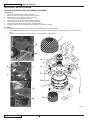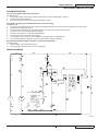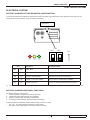
1
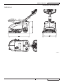
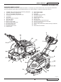
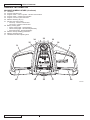
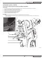
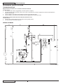
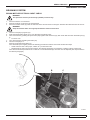
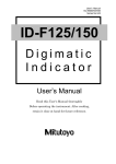
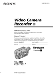
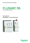
SC350
SERVICE MANUAL
9098840000
Edition 1 2010-10
Printed in Italy
setting standards
SERVICE MANUAL
ENGLISH
TABLE OF CONTENTS
GENERAL INFORMATION............................................................................................................................................... 3
CONVENTIONS............................................................................................................................................................................... 3
MACHINE LIFTING.......................................................................................................................................................................... 3
MACHINE TRANSPORTATION........................................................................................................................................................ 3
OTHER REFERENCE MANUALS.................................................................................................................................................... 3
SAFETY............................................................................................................................................................................................ 3
SYMBOLS........................................................................................................................................................................................ 3
GENERAL INSTRUCTIONS............................................................................................................................................................. 4
TECHNICAL DATA............................................................................................................................................................................ 6
DIMENSIONS................................................................................................................................................................................... 7
MAINTENANCE................................................................................................................................................................................ 8
SCHEDULED MAINTENANCE TABLE............................................................................................................................................ 8
MACHINE NOMENCLATURE.......................................................................................................................................................... 9
DETERGENT SUPPLY SYSTEM................................................................................................................................... 11
SOLUTION SYSTEM SOLENOID VALVE DISASSEMBLY/ASSEMBLY.........................................................................................11
TROUBLESHOOTING.................................................................................................................................................................... 12
WIRING DIAGRAM......................................................................................................................................................................... 12
BRUSHING SYSTEM...................................................................................................................................................... 13
BRUSH MOTOR ELECTRICAL INPUT CHECK............................................................................................................................. 13
BRUSH MOTOR DISASSEMBLY/ASSEMBLY............................................................................................................................... 14
BRUSH DECK DISASSEMBLY/ASSEMBLY.................................................................................................................................. 15
TROUBLESHOOTING.................................................................................................................................................................... 16
WIRING DIAGRAM......................................................................................................................................................................... 16
RECOVERY WATER SYSTEM....................................................................................................................................... 17
VACUUM SYSTEM MOTOR ELECTRICAL INPUT CHECK.......................................................................................................... 17
VACUUM SYSTEM MOTOR DISASSEMBLY/ASSEMBLY............................................................................................................ 18
TROUBLESHOOTING.................................................................................................................................................................... 19
WIRING DIAGRAM......................................................................................................................................................................... 19
OTHER SYSTEMS.......................................................................................................................................................... 20
SCREW AND NUT TIGHTENING CHECK..................................................................................................................................... 20
ELECTRICAL SYSTEM.................................................................................................................................................. 21
BATTERY CHARGER SETTING DIPSWITCH CONFIGURATION................................................................................................ 21
ELECTRICAL COMPONENT LAYOUT.......................................................................................................................................... 22
WIRING DIAGRAM......................................................................................................................................................................... 23
SC350
9098840000
1
ENGLISH
2
SERVICE MANUAL
9098840000
SC350
SERVICE MANUAL
ENGLISH
GENERAL INFORMATION
GENERAL INFORMATION
CONVENTIONS
Forward, backward, front, rear, left or right are intended with reference to the operator’s position, that is to say in driving position.
MACHINE LIFTING
WARNING!
Do not work under the lifted machine without supporting it with safety stands.
MACHINE TRANSPORTATION
WARNING!
Before transporting the machine, make sure that:
–– All covers are closed.
–– The battery is disconnected.
–– The machine is securely fastened to the means of transport.
OTHER REFERENCE MANUALS
The following manuals are available at Nilfisk Literature Service Department:
–– Documentation CD-ROM - Nilfisk Form Number 9098867000
–– SC350 User Manual - Nilfisk Form Number 9098868000
–– SC350 Spare Parts List - Nilfisk Form Number 9098869000
–– SC350 Quick Start Guide - Nilfisk Form Number 9098866000
SAFETY
The following symbols indicate potentially dangerous situations. Always read this information carefully and take all necessary
precautions to safeguard people and property.
SYMBOLS
DANGER!
It indicates a dangerous situation with risk of death for the operator.
WARNING!
It indicates a potential risk of injury for people or damage to objects.
CAUTION!
It indicates a caution related to important or useful functions.
Pay careful attention to the paragraphs marked by this symbol.
NOTE
It indicates a remark related to important or useful functions.
CONSULTATION
It indicates the necessity to refer to the User Manual before performing any procedure.
SC350
9098840000
3
ENGLISH
SERVICE MANUAL
GENERAL INFORMATION
GENERAL INSTRUCTIONS
Specific warnings and cautions to inform about potential damages to people and machine are shown below.
DANGER!
–– Before performing any machine maintenance, repair, cleaning or replacement procedure, disconnect the
battery connector and turn the main switch to “0”.
–– This machine must be used by properly trained operators only.
–– Keep the battery away from sparks, flames and incandescent material. During the normal operation explosive
gases are released.
–– Do not wear jewels when working near electrical components.
–– Do not work under the lifted machine without supporting it with safety stands.
–– Do not operate the machine near toxic, dangerous, flammable and/or explosive powders, liquids or vapours:
This machine is not suitable for collecting dangerous powders.
–– Battery charging produces highly explosive hydrogen gas. Keep the cover open during battery charging and
perform this procedure in well-ventilated areas and away from naked flames.
WARNING!
–– Carefully read all the instructions before performing any maintenance/repair procedure.
–– Before using the battery charger, ensure that frequency and voltage values, indicated on the machine serial
number plate, match the electrical mains voltage.
–– Do not pull or carry the machine by the battery charger cable and never use the battery charger cable as
a handle. Do not close a door on the battery charger cable, or pull the battery charger cable around sharp
edges or corners. Do not run the machine on the battery charger cable.
–– Keep the battery charger cable away from heated surfaces.
–– Do not use the machine if the battery charger cable or plug is damaged. If the machine is not working as it
should, has been damaged, left outdoors or dropped into water, return it to the Service Center.
–– To reduce the risk of fire, electric shock, or injury, do not leave the machine unattended when it is plugged
in. Before performing any maintenance procedure, disconnect the battery charger cable from the electrical
mains.
–– Do not smoke while charging the battery.
4
9098840000
SC350
SERVICE MANUAL
ENGLISH
GENERAL INFORMATION
WARNING!
–– Always protect the machine against the sun, rain and bad weather, both under operation and inactivity
condition. Store the machine indoors, in a dry place: This machine must be used in dry conditions, it must
not be used or kept outdoors in wet conditions.
–– Before using the machine, close all doors and/or covers as shown in the User Manual.
–– Do not allow to be used as a toy. Close attention is necessary when used near children.
–– Use only as shown in this Manual. Use only Nilfisk’s recommended accessories.
–– Take all necessary precautions to prevent hair, jewels and loose clothes from being caught by the machine
moving parts.
–– Pay attention to the machine moving parts. When using the machine, the deck can abruptly turn by 180°.
–– Do not use the machine on incline.
–– Do not tilt the machine more than the angle indicated on the machine itself, in order to prevent instability.
–– Do not use the machine in particularly dusty areas.
–– Use the machine only where a proper lighting is provided.
–– While using this machine, take care not to cause damage to people or objects.
–– Do not bump into shelves or scaffoldings, especially where there is a risk of falling objects.
–– Do not lean liquid containers on the machine, use the relevant can holder.
–– The machine working temperature must be between 0°C and +40°C.
–– The machine storage temperature must be between 0°C and +40°C.
–– The humidity must be between 30% and 95%.
–– When using floor cleaning detergents, follow the instructions on the labels of the detergent bottles.
–– To handle floor cleaning detergents, wear suitable gloves and protections.
–– Do not allow the brushes to operate while the machine is stationary to avoid damaging the floor.
–– In case of fire, use a powder fire extinguisher, not a water one.
–– Do not tamper with the machine safety guards and follow the ordinary maintenance instructions
scrupulously.
–– Do not allow any object to enter into the openings. Do not use the machine if the openings are clogged.
Always keep the openings free from dust, hairs and any other foreign material which could reduce the air
flow.
–– Do not remove or modify the plates affixed to the machine.
–– This machine cannot be used on roads or public streets.
–– Pay attention during machine transportation when temperature is below freezing point. The water in the
recovery tank or in the hoses could freeze and seriously damage the machine.
–– Use brushes and pads supplied with the machine and those specified in the User Manual. Using other
brushes or pads could reduce safety.
–– In case of machine malfunctions, ensure that these are not due to lack of maintenance. Otherwise, request
assistance from the authorised personnel or from an authorised Service Center.
–– If parts must be replaced, require ORIGINAL spare parts from an Authorised Dealer or Retailer.
–– To ensure machine proper and safe operation, the scheduled maintenance shown in the relevant chapter of
this Manual, must be performed by the authorised personnel or by an authorised Service Center.
–– Do not wash the machine with direct or pressurised water jets, or with corrosive substances.
–– The machine must be disposed of properly, because of the presence of toxic-harmful materials (battery, etc.),
which are subject to standards that require disposal in special centres (see Scrapping chapter on the User
Manual).
SC350
9098840000
5
ENGLISH
SERVICE MANUAL
GENERAL INFORMATION
TECHNICAL DATA
General
SC350
Min/max machine length at the handlebar
810/1,270 mm
Machine width
470 mm
Min/max machine height with adjustable handlebar
550/1,000 mm
Weight without battery and with empty tanks
42 kg
Maximum weight with battery and full tanks (GVW)
80 kg
Cleaning width
370 mm
Battery compartment size
350x175x240 mm
Diameter of wheels on fixed axle
200 mm
Brush/pad diameter
370 mm
Rear wheel pressure on the floor (*)
0.5 N/mm2
Brush/pad pressure on the floor
18 kg
Brush/pad pressure with full tank
27 kg
Performance
SC350
Vacuuming
710 mmH2O
Min/max solution flow
SET1: 0.25 litres/min
SET2: 0.5 litres/min
Brush/pad-holder motor speed
140 rpm
Sound pressure level at workstation (ISO 11201, ISO 4871, EN 60335-2-72) (LpA)
65 dB(A) ± 3dB(A)
Machine sound pressure level (ISO 3744, ISO 4871, EN 60335-2-72) (LwA)
84 dB(A)
Vibration level at the operator’s arms (ISO 5349-1, EN 60335-2-72)
< 2.5 m/s2
Vacuum system motor power
200 W
Brush/pad motor power
240 W
Maximum gradient when working
2%
Battery voltage
12 V
Standard battery
12V 55AhC20 AGM Spiralcell
Standard battery autonomy
1 hour
Solution tank capacity
11 litres
Recovery tank capacity
11 litres
(*) Machines have been tested under the following conditions:
• Maximum battery size
• Maximum brush and squeegee size
• Full clean water tank
• Optional components installed
• Weight on wheels checked
• Print on the floor checked on cement for each single wheel
• Result expressed as maximum value for rear wheels
6
9098840000
SC350
SERVICE MANUAL
ENGLISH
GENERAL INFORMATION
DIMENSIONS
P100417
SC350
9098840000
7
ENGLISH
SERVICE MANUAL
GENERAL INFORMATION
MAINTENANCE
The lifespan of the machine and its maximum operating safety are ensured by correct and regular maintenance.
WARNING!
Read carefully the instructions in the Safety chapter before performing any maintenance procedure.
The following table provides the scheduled maintenance. The intervals shown may vary according to particular working conditions,
which are to be defined by the person in charge of the maintenance.
For instructions on maintenance procedures, see the following paragraphs.
SCHEDULED MAINTENANCE TABLE
Daily, after using
the machine
Procedure
Weekly
Every six
months
Squeegee cleaning
Brush cleaning
Tank and vacuum grid cleaning
Squeegee blade check and/or replacement
Battery charging
Screw and nut tightening check
(1)
Brush deck rubber pad check and/or replacement
Brush deck end-of-stroke cable check and/or replacement
Brush deck rubber flange check and/or replacement
(1) And after the first 8 working hours.
8
9098840000
SC350
Yearly
SERVICE MANUAL
ENGLISH
GENERAL INFORMATION
MACHINE NOMENCLATURE
Throughout this Manual you will find numbers in brackets – for example: (2). These numbers refer to the components indicated in
these nomenclature pages. Refer to these pages whenever you need to identify a component mentioned in the text.
1.
2.
3.
4.
5.
6.
7.
8.
9.
10.
11.
12.
13.
14.
15.
Handlebar with control panel (see the following paragraph)
Handlebar inclination adjusting lever
Start-up and program selection knob
Accessory and battery compartment cover
Cover latch
Can holder
Battery connection connector
GEL/AGM battery
Battery charger
Battery charger cable
Battery charger cable holder
Brush/pad-holder deck
Brush deck gearmotor
Squeegee vacuum hose
Splash-shield
16.
17.
18.
19.
20.
21.
22.
23.
24.
25.
26.
27.
28.
29.
Deck bumper wheels
Deck support wheels
Squeegee
Squeegee blades assembly
Squeegee fasteners
Solution tank filler plug
Solution tank
Recovery tank
Transparent cover with vacuum grid
Vacuum grid with automatic shut-off float
Vacuum system motor
Serial number plate/technical data/conformity certification
Fuses
Rear wheels on fixed axle
2
1
24
25
23
3
11
10
12
7
16
28
27
18
5
4
9
20
6
4
19
8
26
21
29
14
13
15
22
17
P100418
SC350
9098840000
9
SERVICE MANUAL
ENGLISH
GENERAL INFORMATION
MACHINE NOMENCLATURE (Continues)
31.
32.
33.
34.
35.
36.
37.
38.
39.
40.
41.
Handlebar
Program selection knob
Program: brush - vacuum system - solution flow activation
Program: brush - solution flow activation
Program: vacuum system activation
Machine switching off (“0”)
Solution flow control switch
• One drop - minimum solution flow
• Two drops - maximum solution flow
Battery warning lights
• Green warning light - charged battery
• Yellow warning light - semi-discharged battery
• Red warning light - discharged battery
Machine start-up enabling push-button
Machine start/stop levers
Handlebar inclination adjusting lever
34
32
33
35
36
41
31
40
38
39
37
40
P100419
10
9098840000
SC350
SERVICE MANUAL
ENGLISH
DETERGENT SUPPLY SYSTEM
DETERGENT SUPPLY SYSTEM
SOLUTION SYSTEM SOLENOID VALVE DISASSEMBLY/ASSEMBLY
Disassembly
1.
2.
3.
4.
5.
6.
7.
Place the machine on a hoisting system (if available), then lift it. Otherwise, drive the machine on a level floor.
Make sure that the battery connector is disconnected.
Remove the cover and the solution and recovery water tanks.
Remove the solenoid valve power supply connector (A).
Disconnect the hoses (B) and (C) under the machine.
Remove the screws (D) and recover the washers.
Remove the solenoid valve (E) upwards.
Assembly
8.
Assemble the components in the reverse order of disassembly and note the following:
• When assembling the solenoid valve (E), the stamped arrow (F) must be tuned in the direction of the solution flow as
shown in the figure.
A
E
F
E
B
D
C
P100420
SC350
9098840000
11
ENGLISH
SERVICE MANUAL
DETERGENT SUPPLY SYSTEM
TROUBLESHOOTING
Small amount of solution or no solution reaches the brush
Possible causes:
1. The solution tank valve is clogged/dirty or broken (clean or replace).
2. The solenoid valve (EV) is broken or there is an open in the electrical connection (replace the solenoid valve/repair the
electrical connection).
3. There is debris in the solution tank clogging the output hole (clean the tank).
4. There is debris in the solution hoses and/or reducer clogging the flow (clean the hose).
The solution reaches the brush also when the machine is off
Possible causes:
1. There is dirt or calcium deposit on the solenoid valve gasket (clean).
2. The solenoid valve is broken (replace).
WIRING DIAGRAM
P100421
12
9098840000
SC350
SERVICE MANUAL
ENGLISH
BRUSHING SYSTEM
BRUSHING SYSTEM
BRUSH MOTOR ELECTRICAL INPUT CHECK
WARNING!
This procedure must be performed by qualified personnel only.
1.
2.
3.
Drive the machine on a level floor.
Remove the brush, as shown in the User Manual.
Place two wooden shims (A) under the side area of the deck as shown in the figure. Wooden shim thickness must be 40 mm.
WARNING!
Keep the wooden shims at an appropriate distance from the brush hub.
4.
5.
6.
7.
8.
Turn the knob (32) to program (34).
Apply the amperometric pliers (A) on one cable (B) of the brush motor.
Turn on the brush by pressing the push-button (39) together with the levers (40), then check that the motor electrical input (C)
is:
• 6 to 8 A at 12V
Turn off the brush by releasing the levers (40).
Turn the knob (32) to “0”.
Remove the amperometric pliers (A).
If the electrical input is higher, perform the following procedures to detect and correct the abnormal input:
• Check if there is dust or dirt (ropes, cables, etc.) on the brush hubs.
• Disassemble the motor (see the procedure in the relevant paragraph), and check the condition of all its components.
If the above-mentioned procedures do not lead to a correct electrical input, the motor must be replaced (see the procedure in
the relevant paragraph).
A
B
C
P100422
SC350
9098840000
13
ENGLISH
SERVICE MANUAL
BRUSHING SYSTEM
BRUSH MOTOR DISASSEMBLY/ASSEMBLY
Disassembly
1.
2.
3.
4.
5.
6.
7.
8.
Place the machine on a hoisting system (if available), then lift it. Otherwise, drive the machine on a level floor.
Make sure that the battery connector is disconnected.
Disconnect the gearmotor connector (A) and the detergent hose (B).
Lift the machine and remove the brush.
Remove the screw (C), then remove the hub assembly (D).
Remove the 4 screws (E).
Remove the gearmotor (F).
Recover the key (G).
Assembly
9.
Assemble the components in the reverse order of disassembly.
NOTE
For further information on deck components see the Spare Parts List.
F
C
B
D
E
G
E
C
P100423
14
9098840000
SC350
SERVICE MANUAL
ENGLISH
BRUSHING SYSTEM
BRUSH DECK DISASSEMBLY/ASSEMBLY
Disassembly
1.
2.
3.
4.
5.
6.
7.
8.
Place the machine on a hoisting system (if available), then lift it. Otherwise, drive the machine on a level floor.
Make sure that the battery connector is disconnected.
Disconnect the vacuum hose from the squeegee.
Disassemble the end-of-stroke cable fastener.
Lift the machine and remove the brush.
Remove the screw and the hub assembly (see the previous paragraph).
Remove the 4 screws (A), the flange (B) and disassemble the brush deck (C).
Check the rubber pads (D) for integrity; if necessary replace them by removing the 3 nuts (E).
NOTE
The rubber pads (D) allow the deck mechanical rotation by creating friction on the rotating brush.
9.
Check the rubber joint (F) for integrity; if necessary remove the 13 screws (G), recover the nuts, flanges (H) and (I), and
replace it.
NOTE
The rubber joint (F) absorbs blows and vibrations between the deck and the machine.
Assembly
10. Assemble the components in the reverse order of disassembly and note the following:
• When the rubber joint (F) is fastened to the deck, install the flanges (I) by placing their tooth (J) as shown in the figure.
NOTE
For further information on deck components see the Spare Parts List.
A
B
A
E
D
C
G
H
F
I
J
P100424
SC350
9098840000
15
ENGLISH
SERVICE MANUAL
BRUSHING SYSTEM
TROUBLESHOOTING
Open circuit
The resettable fuse (F1) determines an open in the supply circuit of the brush deck motor. This system allows to prevent the circuits
from being damaged under overload conditions.
The open in the fuse can be caused by the following:
1. Short circuit in the brush motor wiring harness; fault in the motor.
2. Overvoltage of the gearmotor.
One brush do not turn
Possible causes:
1. The brush motor electromagnetic switch wiring harness is damaged (repair).
2. The brush motor electromagnetic switch (ES1) is damaged (replace).
3. The brush motor fuse (F1) is tripped (reset).
4. The motor is faulty (repair or replace).
5. The wiring harness is damaged (repair).
Malfunction of the brush deck mechanical rotation system
Possible causes:
1. The rubber pads between deck and brush are worn (replace).
2. The rubber damping joint is worn (replace).
3. The end-of-stroke cable is broken (replace).
WIRING DIAGRAM
P100425
16
9098840000
SC350
SERVICE MANUAL
ENGLISH
RECOVERY WATER SYSTEM
RECOVERY WATER SYSTEM
VACUUM SYSTEM MOTOR ELECTRICAL INPUT CHECK
WARNING!
This procedure must be performed by qualified personnel only.
1.
2.
3.
4.
5.
Remove the solution and recovery water tanks.
Apply the amperometric pliers (A) on the cable (B).
Turn the knob (32) to program (35).
Check that the motor electrical input is between 15 and 18 A at 12 V.
Turn the knob (32) to “0”.
Remove the amperometric pliers (B).
If the electrical input is higher than specified, disassemble the vacuum system motor (see the procedure in the relevant
paragraph), and check the condition of its moving parts.
If the procedure do not lead to a correct electrical input, it is necessary to replace the motor.
A
C
B
P100426
SC350
9098840000
17
SERVICE MANUAL
ENGLISH
RECOVERY WATER SYSTEM
VACUUM SYSTEM MOTOR DISASSEMBLY/ASSEMBLY
Disassembly
1.
2.
3.
4.
5.
6.
7.
8.
Remove the solution and recovery water tanks.
Make sure that the battery connector is disconnected.
Disconnect the 2 connectors (A) of the motor (B).
Remove the acoustic insulation panel (C).
Remove the screws (D), recover the washers and nuts.
Remove the motor cover (E) and recover the gasket (F).
Remove the motor (B) and the acoustic insulation pipe (G)
Check the gasket (F) and the gasket (H) for efficiency. If necessary, replace.
Assembly
9.
Assemble the components in the reverse order of disassembly and note the following:
• When installing the gasket (I) into the housing (J) turn it until the lower tooth (K) and upper teeth (L) are as shown in the
figure.
• Install the motor (B) with the power supply contacts as shown in the figure (M).
C
B
A
H
L
D
K
I
D
E
J
L
F
B
B
M
I
G
P100427
18
9098840000
SC350
SERVICE MANUAL
ENGLISH
RECOVERY WATER SYSTEM
TROUBLESHOOTING
The vacuum system motor does not turn on
Possible causes:
1. The vacuum system motor wiring harness is damaged or disconnected (repair / connect).
2. The fuse (F2) is blown (replace).
3. The vacuum system motor is faulty (check the electrical input).
Dirty water vacuuming is insufficient or there is no vacuuming
Possible causes:
1. The vacuum grid with automatic shut-off float is activated because the recovery tank is full (empty the recovery tank).
2. The debris tray is clogged (clean).
3. The vacuum grid with automatic shut-off float is dirty, or the vacuum pre-filter is dirty (clean).
4. The tank cover is not correctly positioned (adjust).
5. The tank cover gasket is not efficient (replace/clean).
6. The vacuum system motor filter is dirty (clean).
7. The squeegee or the vacuum hose is clogged or damaged (clean or repair/replace).
8. The vacuum gaskets are damaged or do not match perfectly (repair or replace).
The squeegee leaves lining on the floor or does not collect water
Possible causes:
1. There is debris under the blade (remove).
2. The squeegee blade edges are torn or worn (replace).
WIRING DIAGRAM
P100428
SC350
9098840000
19
ENGLISH
SERVICE MANUAL
OTHER SYSTEMS
OTHER SYSTEMS
SCREW AND NUT TIGHTENING CHECK
1.
2.
3.
4.
7.
Drive the machine on a level floor with the recovery tank empty.
Turn the ignition key to “0” and disconnect the batteries.
Carefully lift the tank assembly.
Then check:
• Tightening of mounting screws and nuts
• Correct position of fasteners
• Visible faults in the components
• Leaks
Carefully lower the tank assembly.
20
9098840000
SC350
6?
6<<
������������
;2�\>;22?
3!3$�>@������30�6&2;��>@���������
�==
��
��"$�+&�+��"�
�����BE����
����;�5��6��"����5��6��*�������+�
SERVICE
8 �"�#$�9MANUAL
6<<
6<<
������������=2116B
3!3$>21�����2A3�2�06??2?0��23?�>���
��������
ENGLISH
ELECTRICAL SYSTEM
G]H�����12������������������������������������12��������������������������������������,�
ELECTRICAL SYSTEM
���������������������������������
BATTERY CHARGER SETTING DIPSWITCH CONFIGURATION
�����������������������������������,���������������������������.�
To change the dipswitch
configuration, please remove the round black cap located close to the openings on the bottom of the
������������������������������������������������������������G��������
charger (see the picture
below), using a tool like a screwdriver.
�������������H,���������������.���������������
"+27@+8!*
������"�&�"���3!3�6+�3@���3+0B3�����6?<3>!;��36?
��9
��9
��?
�������������������������
����������������������������
SW1
�BC
�+"
LED CODE (*)
�+�
��������8D9
��
��
���
���
��
����������<�
CHARGING CURVE
�������12��
DP1
6?
DP2
6? LEDs������������>;22?
Battery
ON
ON6?
6<< of GREEN
2 flashes
;2�\>;22?
ON
�==
OFF
�� of RED & GREEN
2 flashes
�����BE����
����;�5��6��"����5��6��*�������+�
IUIa-AGM for8 DISCOVER
AGM batteries
�"�#$�9
OFF
6<<
ON
6<< of YELLOW
������������=2116B
2 flashes
& GREEN
3!3$>21�����2A3�2�06??2?0��23?�>���
IUIa-OPTIMA��������
for OPTIMA batteries (default)
OFF
������������
��"$�+&�+��"�
3!!#$>21�������������>�������>@���������
3!3$�>@������30�6&2;��>@���������
IUU0-GEL for generic Gel and AGM batteries
G]H�����12������������������������������������12��������������������������������������,�
OFF
2 flashes of YELLOW
IUIa-GEL for EXIDE SONNENSCHEIN Gel batteries
���������������������������������
(*) The LED code is shown by the battery status LEDs every time the charger is powered on, before to start the charging cycle.
�����������������������������������,���������������������������.�
������������������������������������������������������������G��������
BATTERY CHARGER
ADDITIONAL FUNCTIONS
�������������H,���������������.���������������
The battery charger is also used for:
1. Check the battery voltage during machine operation. "+27@+8!*
2. Display the battery status through the LED (EB1).
3. Stop the machine when the battery is discharged.
4. Avoid the machine operation during the battery recharging.
For this porpouse the following auxiliary battery charger contacts are used:
–– B1: (ref. + 12V) input signal for switching on the machine.
–– B2: (refer to 0V) output signal for activating machine functions.
SC350
9098840000
21
ENGLISH
SERVICE MANUAL
ELECTRICAL SYSTEM
ELECTRICAL COMPONENT LAYOUT
Key
BAT
12V battery
CH
Battery charger
D1
Diode
D2
Diode
EB1
Battery charger electronic board
ES1
Brush electromagnetic switch
ES2
Vacuum system relay
EV
Solution solenoid valve
F1
Brush resettable fuse
F2
Vacuum system fuse (30 A)
F3
Selector fuse (5 A)
M1
Brush motor
M2
Vacuum system motor
SW1
Rotary function selector
SW2
M1-EV enabling switch
SW3
Solution rate switch
T1
Solenoid valve timer
EB1
T1
ES2
ES1
F1
F3
SW2
F2
SW3
D2
SW1
BAT
CH
M1
EV
M2
D1
P100429
22
9098840000
SC350
SERVICE MANUAL
ENGLISH
ELECTRICAL SYSTEM
WIRING DIAGRAM
Key
Colour codes
BAT
12V battery
BK
Black
CH
Battery charger
BU
Blue
D1
Diode
BN
Brown
D2
Diode
GN
Green
EB1
Display LED electronic board
GY
Grey
Brush electromagnetic switch
OG
Orange
ES2
Vacuum system relay
PK
Pink
EV
Solution solenoid valve
RD
Red
F1
Brush resettable fuse
VT
Violet
F2
Vacuum system fuse (30 A)
WH
White
F3
Selector fuse (5 A)
YE
Yellow
M1
Brush motor
M2
Vacuum system motor
SW1
Rotary function selector
SW2
M1-EV enabling switch
SW3
Solution rate switch
T1
Solenoid valve timer
ES1
P100430
SC350
9098840000
23
setting standards
Nilfisk-Advance SpA
Registered office: Via F. Turati 16/18, 20121 Milano
Administrative office: Strada Comunale della Braglia n° 18
26862 Guardamiglio (Lodi)
Phone: +39 0377 451124 - Fax: +39 0377 51443
www.nilfisk.com