1
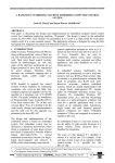
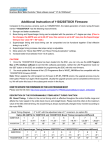
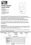
Switching power supply SP-R
Operating instructions
2010
Contents
SAFETY INSTRUCTIONS.................................................................................................................................. 2
SPECIAL SYMBOLS............................................................................................................................................... 2
SAFETY INSTRUCTION AND COMMANDS .............................................................................................................. 2
INTRODUCTION................................................................................................................................................. 3
DESCRIPTION..................................................................................................................................................... 4
PARAMETERS..................................................................................................................................................... 6
INSTALLATION .................................................................................................................................................. 7
MECHANICAL MOUNTING .................................................................................................................................... 7
ELECTRICAL WIRING ........................................................................................................................................... 7
BATTERY CONNECTION ....................................................................................................................................... 9
SETTINGS........................................................................................................................................................... 10
OPERATION ...................................................................................................................................................... 11
MAINTENANCE ................................................................................................................................................ 14
SERVICE AND SERVICE ASSISTANCE....................................................................................................... 15
GUARANTEE TERMS ...................................................................................................................................... 16
1
Safety Instructions
Special symbols
Touching the electrical equipment may be fatal
Warning, read operating instructions
Warning, battery
Do not disposed together with domestic waste
Safety instruction and commands
1. Only authorized and informed person can work on this device
2. Earth the device properly
3. Disconnect all wiring before any manipulation
4. Do not unplug any connector under voltage
2
Introduction
Switching chargers of the SP-R series are intended for charging station batteries of
nominal voltage 110V and 220V.
Chargers are suitable for supplying DC circuits with combination of charging station
batteries. Switching chargers of the SP-R series fully comply with the requirements of the
station battery charging standard EUROBAT.
Power supply unit offers function of temperature compensation of charging voltage,
inputs wiring resistance measurement or fast charging. Different charging characteristics can
be used- IU0, IUU0 etc.
3
Description
The power unit is fit into 3U 19`` rack and is designed for built-in mount into
switchgears. All connection and signalling points are situated in front panel.
Compact construction of the charger brings all advantage of switching units in
comparison with standard power supply unites equipped with transformer – primarily lower
weight and smaller dimensions. Advanced software equipment leads to higher user comfort
and to the merging different measure devices into one device.
Nominal output current is 50A for voltage 110V DC and 25A for voltage 220V DC. In
case of need up to 16 power units can be set together in parallel operation mode, with
possibility of changeover of wrong module during operation without blackout. Output voltage
fuses are placed in rear panel.
The power unit has force cooling which is controlled according to momentary
temperature of the cooler. This solution increases lifetime of ventilator and contributes to lownoise run of the unit.
Regulation is controlled by processor card ProDrive III equipped DSP processor Texas
Instruments.
Processor control with combination of power electronics elements temperature
measurement allows short-term operation by reducing output current as well during
deterioration of temperature conditions.
The unit can be equipped by 3“ HMI colour LCD panel. The HMI panel can be fit in
switchboard as well.
Type code
-PEG- xx/xx SP-R
nominal voltage
nominal current
switching charger
4
Picture 1 Dimensions SP-R with LCD panel
5
Parameters
Basic types
Uin
3x 400/230 V
Iin
16A
fin
30-70 Hz
Un
110 V DC
220 V DC
Imax
50A
25A
Current ripple
Efficiency
Power factor
Parallel operation
Short circuit protection
LCD
Temperature compensation
Fast charging
Communication
Logical inputs
Analog inputs
Logical outputs
Operational temperature
Dimension
Weight
Protection
<3%
92 - 95%
0,98
YES
YES
YES
YES
YES
RS232, RS485
2
1
9 (230 V AC/5 A)
-25 to +40 °C
360 x 484 x 133 mm
25 kg
IP 20
Options
PT100/PT1000
3,5" HMI
Load current measurement
Table 1 Parameters
6
Installation
Mechanical mounting
The power unit
switchgears. The unit
corresponding device.
(picture 2). Mounting
picture 1.
is fit into 3U 19`` rack and is designed for built-in mount into
is necessary to mount into factory made support panel or into
The unit is fixed by four screw-bolts M6 going throw front panel
dimensions including mounting holes dimension are shown on
Picture 2 Mounting
The unit has to be mounted only in horizontal position. Sufficient room for inflow and
outlet of cooling air is necessary – 50mm in front of unit, 100mm at back of unit. The
surrounding temperature must be in range from -25°C to +40°C, otherwise right function can
not be warrant.
Electrical wiring
All connection and signalling points are situated in front panel.
Picture 3 Connectors
7
Picture 4 Connector wiring
Function
Connector 1 PT100/PT1000
Voltage
Connector 2 2 digital inputs
3 logical outputs; relay with
common pin
2 logical outputs; relay with
Connector 4 common pin
external display supply
Connector 3
internal 24 V DC or external 110/220 V DC
(set by manufacturer)
230 V AC / 5 A
48 V DC / 5A
230 V AC / 5 A
48 V DC / 5A
24 V DC (set by manufacturer)
Connector 5
5 logical outputs; relay with
common pin
230 V AC / 5 A
48 V DC / 5A
Connector 6
Connector 7
Connector 8
Connector 9
Battery output
Supply voltage
Communication port RS 485
Communication port RS 232
110 V/220 V DC (set by unit type)
3x400/220V AC + PE
Table 2 Connectors
In case of external HMI panel mounting is necessary to connect port RS232 with the
charger and provide power supply 24V DC for HMI panel. For the power supply connector 4
(OUT 5) can be used, terminals 14 (+) and 16 (-). This possibility has to be set by
manufacturer.
The isolation of the wires plugged into connectors despatch only in needed length,
touchable bare wiring is not allowable
Screw-terminals of connectors 1-5 are to be tightening by torque 0,5Nm, connector 6
by torque 1,5Nm and connector 7 by torque 2Nm.
Earth wire on terminal PE in connector 7 must be plug-in properly.
8
Battery connection
The inputs wiring resistance can be measured before battery plug-in. For this
measurement, battery supply wiring is unplugged on battery, the wiring is connected (charger
far end) and the charger provide resistance measurement. The measurement is release by
switching input IN2 (function “Start of resistance measurement”). Charger works with the
result of measurement and the output voltage is adjusted which means, charger compensate
resistance of supply wiring.
After measurement the battery can be plug-in, it is necessary to observe the procedure
recommended by producer of batteries.
The function for wiring resistance measurement is optional, not all chargers can
provide it. Before application of this function consult the possibility with manufacturer.
Observe the right battery polarity!
Only battery with nominal voltage the same as nominal output voltage of charger can
be connected.
9
Settings
Inputs and outputs are programmable which means adjustment of the power unit to
concrete application. For each input and output one or up to all switching possibilities can be
set (see table 3). Voltage and current of individual inputs and outputs are mentioned in
chapter “Installation”, table 2.
Each input and output can be logically inverted.
IN
External failure
Fast charging start
Charger shutdown
Resistance measurement start
ON/OFF
Siren silence
OUT
Charger
failure
Battery
diagnostics
Power supply loss
Over voltage
Under voltage
Fusses
Summary fault
Over current
Battery over voltage
Battery not charged
30% capacity left
10% capacity left
Battery discharged
Charging with higher
voltage
Charging with lower
voltage
Run
Siren
Table 3 Inputs and outputs
10
Unit supplied from DC
Unit supplied from DC
Unit supplied from DC
Charger shutdown
Battery unfasten
Operation
Operation states signalling
The unit can be equipped with HMI LCD panel which is used for settings and for
signalling of operation states or fault reports.
All units are equipped with set of LED diodes for signalling of basic operation states.
LED diode
Meaning
RUN
Supply OK
Charging OK
Opt. Func.
Error
Operation, without faults
Power supply 400V is present
Charging voltage in tolerance
Optional function is active
Unit failure or fault
LCD display function
LED diode signalling is active as well in units with LCD panel. The panel can be
mounting in switchgear or on other places far form charger rack (central control board etc.).
There are four basic schemes available on the HMI display; buttons on panel screen
bottom are used for changes.
The panel is control by touching on selected point, is strictly forbidden to use objects
which could damage the screen (sharp object, screw-driver etc.).
Overview
Basic screen for fast diagnostics. Text description is shown as well as measured value
of charger, battery and output voltage.
11
Charger
Screen serves detailed information about charger inner electrical values, temperatures
of components and about actual status of all inputs and outputs.
The list of error-states could be invoked from the screen by pressing button “Errors”.
Error history is available from the screen by pressing “History on”, for return to on-line
mode button “History off” is used.
Battery
Actual status of battery is shown, in text description and as a measured value of battery
voltage.
12
Settings
Screen is used for function setting of individual inputs and outputs and for setting of
other operation parameters.
Password is necessary for entering – 1590. Press the button „Password“ for enter,
insert the password and confirm by pressing „Enter“ and „RET“. For return without password
insert press the button “ESC”. Last insert number can be deleting by pressing “Clear”.
Settings mode is used for setting inner values necessary for unit correct
operation. It is strictly forbidden to change inner parameters without consulting with the
manufacturer.
Test mode is used for unit service setting and is strictly forbidden to use this
mode without consulting with the manufacturer.
Error summary
Errors are announced on unit screen and by acoustic siren.
13
Maintenance
The device does not need any regular maintenance. The regular maintenance
according to valid norms ČSN-EN – electro technical devices has to perform. This
maintenance consists of visual control of the device, cleaning the device (best is via vacuum
cleaner) and of control of proper tighten of screw joints.
This maintenance has to be performed in terms according to status of surroundings,
but maximum 6 months duration.
14
Service and service assistance
In case of queries or problems with the device contact the producer:
PEG spol. s r.o., Baarova 49, 140 00 Prague 4
Plant Kolbenova 922/5a, 190 00 Prague 9
www.peg.cz
[email protected]
Tel: 281 087 521, fax: 281 087 522
GSM
O2: 724 366 435, T-mob: 731 118 119
Please, let us know about these details:
•
Serial number of charger
•
Date of first failure
•
Failure description
15
Guarantee terms
Guarantee for material failure, construction failure and treatment and machining failure
is provided for the devices, duration 24 months. The guarantee could be prolonged only via
contract.
Producer is not responsible for any damage caused by wrong mounting; wrong
operating conditions, settings change or any other conditions which are not in accordance
with documentation. Producer is not responsible for consequences of wrong usage.
Producer of monitor reserves the right to change technical data specification and
details without former notice.
16