1
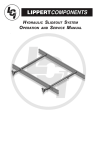
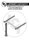
H����-S��� S����-O�� S�����
SERVICE MANUAL
Rev: 01.12.2015
Page 1
Hydro-Sync Slide-out System Service Manual
TABLE OF CONTENTS
Safety Information
Product Information
Operation
Extending Slide-out Room
Retracting Slide-out Room
Maintenance
Mechanical
Electrical
Fluid Filling Procedure
Troubleshooting
Manual Operation
Troubleshooting Chart
Troubleshooting – Power Unit
Troubleshooting - Electrical
Troubleshooting – Checking For Bad Cylinder
Wiring Diagram
Main Components
Rev: 01.12.2015
3
3
4
4
4
5
5
6
6
7
7
8
9
9
9
10
10
Page 2
Hydro-Sync Slide-out System Service Manual
Safety Information
Failure to act in accordance with the following may result in death or serious personal injury.
The Lippert Hydro-Sync Slide-out System is intended for the sole purpose of extending and retracting the slide-out
room. Its function should not be used for any other purpose or reason other than to actuate the slide-out room. To
use the system for any reason other than what it is designed for may result in death, serious injury, and/or damage
to the coach.
Before actuating the system, please keep these things in mind:
1.
2.
3.
4.
Parking locations should be clear of obstructions that may cause damage when the slide-out room is
actuated.
Be sure all persons are clear of the coach prior to the slide-out room actuation.
Keep hands and other body parts away from slide-out mechanisms during actuation. Death or severe
injury may result.
To optimize slide-out actuation, park coach on solid and level ground.
Product Information
The Lippert Hydro-Sync Slide-out System is a hydraulic cylinder drive system. Utilizing a bi-directional
electric motor to actuate the pump, moving fluid from the reservoir into the hydraulic cylinders to extend
the room and pumping fluid back to the reservoir to retract the slide-out. The Lippert Hydro-Sync Slide-out
System is designed as a negative ground system.
There are no serviceable parts within the power unit. If the motor, manifold, pump or reservoir fails, the
entire power unit MUST be replaced.
Disassembly of the motor voids the warranty.
Mechanical portions of the slide-out system are replaceable. Contact Lippert Components, Inc. to obtain
replacement parts.
Rev: 01.12.2015
Page 3
Hydro-Sync Slide-out System Service Manual
Operation
Failure to act in accordance with the following may result in death or serious personal injury.
Always make sure that the slide-out room path is clear of people and objects before and during operation of
the slide-out room.
Always keep away from the slide rails when the room is being operated. The gear assembly may pinch or
catch on loose clothing causing personal injury.
Install transit bars (if so equipped) on the slide-out room during storage and transportation.
Extending Slide-out Room
1.
2.
3.
4.
5.
Level the unit.
Verify the battery is fully charged and hooked-up to the electrical system.
Remove the transit bars (if so equipped).
Press and hold the IN/OUT switch (Fig. 1B) in the OUT position until the room is fully extended and
stops moving.
Release the switch, which will lock the room into position.
Note: If the slide-out switch is held after the room is fully extended, the control will sense that the room
has stopped and will shut off the motor after a few seconds.
Retracting Slide-out Room
1.
2.
3.
Verify the battery is fully charged and hooked-up to the electrical system.
Press and hold the IN/OUT switch (Fig. 1A) in the IN position until the room is fully retracted and stops
moving.
Release the switch, which will lock the room into position.
Note: If the slide-out switch is held after the room in fully retracted, the control will sense that the room has
stopped and will shut off the motor after a few seconds.
4.
Install the transit bars (if so equipped).
Fig. 1
A
B
Rev: 01.12.2015
Page 4
Hydro-Sync Slide-out System Service Manual
Maintenance
The Lippert Hydro-Sync Slide-out System has been designed to require very little maintenance. To ensure the long
life of your slide-out system, read and follow these few simple procedures.
Do not work on your slide-out system unless the battery is disconnected. Failure to act in accordance
with the following may result in death or serious personal injury.
The Lippert Hydro-Sync Slide-out System has been static tested to over 6,000 continuous cycles without any
noticeable wear to rotating or sliding parts. It is recommended that when operating in harsh environments and
conditions (road salt, ice buildup, etc.) the moving parts be kept clean and can be washed with mild soap and
water. No grease or lubrication is necessary and in some situations may be detrimental to the environment and
long-term dependability of the system.
Mechanical
Although the system is designed to be almost maintenance-free, actuate the room once or twice a week to keep
the seals and internal moving parts lubricated.
Check for any visible signs of “leaking” before and after movement of the system and the coach.
When the room is out, visually inspect the Inner and Outer Assemblies. Refer to Fig. 2 for location of inner
assemblies. Check for excess buildup of dirt or other foreign material and remove any debris that may be present.
If the system squeaks or makes any noises it is permissible to apply a coat of lightweight oil to the drive shaft and
roller areas but remove any excess oil so dirt and debris do not buildup. DO NOT USE GREASE.
Fig. 2
Outer Assembly
Inner Assembly
Rev: 01.12.2015
Page 5
Hydro-Sync Slide-out System Service Manual
Electrical
For optimum performance, the slide-out system requires full battery current and voltage. The battery MUST be
maintained at full capacity. Other than good battery maintenance, check the terminals and other connections at
the battery, the control switch and the pump motor for corrosion and loose or damaged terminals. Check motor
leads under the coach chassis. Since these connections are subject to damage from road debris, be sure they are in
good condition.
NOTe: The Lippert Hydro-Sync Slide-out System is designed to operate as a negative ground system. A
back to the battery is not needed. It is important the electrical components have good wire to
chassis contact. To ensure the best possible ground, a star washer should be used. Over 90% of
unit electrical problems can be attributed to bad ground connections.
NOTe: For long-term storage: It is recommended that the room be closed (retracted) and if your unit is
equipped with the IRC room control, it is recommended all of the control knobs be kept in the
closed position.
IF YOU HAVE ANY PROBLEMS OR QUESTIONS CONSULT YOUR LOCAL AUTHORIZED DEALER OR CALL LIPPERT AT:
(866) 524-7821.
Fluid Filling Procedure
The Lippert Hydro-Sync Slide-out System uses automatic transmission fluid (ATF). Any ATF can be used. A full
synthetic or synthetic blend works best such as Dexron III or Mercon 5. For best operation, fill system within ½” of
the top when all slide-outs are completely retracted. The see through reservoir makes it easy to check oil level. It
is recommended that the oil level be checked prior to operating the system. Make sure the breather cap is free of
contamination before removing, replacing or installing.
FILLING DIReCTIONS
Remove Breather/Fill Cap (Fig. 3).
Pour ATF into Breather/Fill opening.
Fig. 3
BReATHeR/FILL CAP
NOTe: Do not allow any contamination
into reservoir during fill
process.
NOTe: Standard reservoir holds
approximately 1 quart ( .946
liters ) of ATF.
Fill to within ½” of top.
Replace Breather/Fill Cap when finished.
NOTe: System is self-purging. By
simply cycling the system 2-3
times, any air in the system will
be forced back to the reservoir
and out of the Breather/Fill
Cap.
Rev: 01.12.2015
Page 6
Hydro-Sync Slide-out System Service Manual
Troubleshooting
The Lippert Hydro-Sync Slide-out System is only one of four interrelated slide-out room system components. These
four components are as follows: chassis, slide-out room, coach and Lippert Hydro-Sync Slide-out System. Each one
needs to function correctly with the others or misalignment problems will occur.
Every coach has its own personality and what may work to fix one coach may not work on another even if the
symptoms appear to be the same.
When something restricts room travel, system performances will be unpredictable. It is very important that slide
rails, inner and outer, be free of contamination and allowed to travel freely the full distance or “STROKE.” Ice or mud
buildup during travel is an example of some types of contamination that may occur.
When beginning to troubleshoot the system, make sure the battery is fully charged, there are no visible signs of
external damage to the actuator, motor or rails and that the motor is wired properly and all connections are secure.
You can adjust room extension by modifying the position of the adjustment coupler.
During troubleshooting, remember, by changing, altering or adjusting one thing, it may affect something else. Be
sure any changes do not create a new problem.
Additional information on the Lippert Hydro-Sync Slide-out System is available by calling 866-524-7821.
Manual Operation
The Lippert Hydro-Sync Slide-out System can be run with auxiliary power devices like electric drills, ratchet
wrenches or cordless screwdrivers. In the event of electrical or system failure, this manual method of extending
and retracting the slide-out room can be used. A standard hand held drill is all that is required. A standard 38"
room will take approximately 45 seconds to retract.
1. Remove protective label (Fig 4).
2. Using a standard hex bit, insert into auxiliary drive device, i.e. cordless drill or screwdriver or ratchet
wrench.
3. Insert hex bit into coupler found under protective label (Fig. 5).
4. Run drill forward or clockwise to retract slide-out room and in reverse or counterclockwise to extend
slide-out room.
Fig. 5
Fig. 4
Rev: 01.12.2015
Page 7
Hydro-Sync Slide-out System Service Manual
Troubleshooting Chart
The following troubleshooting chart outlines some common problems, their causes and possible corrective actions.
When reference is made to a “Power Unit,” the term includes the motor and the actuator as a complete unit. All
Power Units are shipped from the factory with a serial number and date code, which should be given to the service
technician when asking for assistance.
What Is Happening?
Room doesn't move when
switch is pressed.
Power unit runs, room does not
move.
Power unit runs, room moves
slowly.
Room drifts in both IN & OUT
positions.
Why?
Restrictions both inside and
outside of unit.
Low voltage, blown fuse,
defective wiring.
Power unit not functioning.
Restrictions both inside and
outside of unit.
Low hydraulic fluid level.
Low battery, poor ground,
extremely low outside
temperature.
Leaking cylinder.
Check for leaks in the hydraulic
system.
What Should Be Done?
Check for and clear restriction.
Check battery. Charge battery or add
auxiliary power source.
Check battery terminals and all other
wiring. Look for loose or corroded
connections.
See "Power Unit Troubleshooting" page 9.
Check for and clear restriction.
Check for leaks. See Fig. 3 for filling
instructions.
Charge battery and check ground wire.
See "Checking for Bad Cylinder" page 9.
Tighten fittings.
After checking all connections, cycle pump
several times IN & OUT.
Leaking cylinder seal.
See "Checking for Bad Cylinder" page 9.
Fluid bypassing cylinder position. See "Checking for Bad Cylinder" page 9.
In the Closed position, room
Hose from pump is leaking.
Tighten fitting or replace hose.
drifts OUT.
After checking all connections, cycle pump
Air in system.
several times IN & OUT.
Loose mounting bolts.
Tighten mounting bolts.
Hose from pump is leaking.
Tighten fitting or replace hose.
In the Open position, room drifts
Leaking cylinder seal.
See "Checking for Bad Cylinder" page 9.
IN.
Fluid bypassing cylinder piston.
See "Checking for Bad Cylinder" page 9.
Rev: 01.12.2015
Air in system.
Page 8
Hydro-Sync Slide-out System Service Manual
Troubleshooting – Power Unit
Before attempting to troubleshoot the Power Unit, make sure an adequate power source is available. The unit
batteries should be fully charged or the unit should be plugged into to A/C service with batteries installed. Do not
attempt to troubleshoot the Power Unit without assuring a full 12V DC charge
The following tests require only a DC voltmeter (or DC test light) and a jumper lead.
Step 1. Attach voltmeter (or test light) leads to the negative and positive switch terminals on back of wall
switch (See Fig. 6). Does the meter indicate 12V DC? If YES, see Step 2; if NO see Step 3.
Step 2. If YES, at the motor, check the incoming leads to 12V DC (if necessary, disconnect leads at wire
splices). Does meter indicate 12V DC? If YES, Power Unit needs to be replaced. The motor is not
field serviceable. DO NOT ATTEMPT TO REPAIR. If NO, Inspect all wires and connections between
the wall switch and the motor. Repair connections as necessary. Recheck as in Step 1.
Step 3. If NO, Inspect all connections between battery and switch. Inspect 50A Auto -reset Circuit Breaker
(See Fig. 6). Recheck as above in Step 1.
Troubleshooting - Electrical
Since there are no field serviceable parts in the motor of the Power Unit, electrical troubleshooting and service is
limited to replacing only those components as previously outlined.
Thorough inspection of wiring and connections is the only other electrical service that can be performed.
Troubleshooting – Checking For Bad Cylinder
1.
2.
Retract (close) the slide-out (room) completely.
Loosen hose from “E” (extend) port on the manifold of the Power Unit.
Do not attempt to run room out with the “E” port hose loose. The system will experience RAPID
FLUID LOSS.
3.
4.
5.
Plug opening on manifold to prevent drawing air into the system.
Energize the Power Unit to retract (close) room.
Continue to run the room in and watch for fluid flow from hose/port “E”. Fluid flow greater than a few
drops will indicate internal cylinder leaking (bypassing of piston seal). If there is no fluid flow, reconnect
hose to “E” port and tighten.
Be sure to reconnect and tighten hose at the “E” port before attempting to extend (open) the room
or the system will experience RAPID FLUID LOSS.
Contact qualified technician if there is excessive fluid flow. The cylinder should not be repaired in the field.
Refill the Power Unit Reservoir as recommended on page 6 of this manual.
Rev: 01.12.2015
Page 9
Hydro-Sync Slide-out System Service Manual
Wiring Diagram
Fig. 6
BATTeRY
ReSeRVOIR
50 AMP AUTO-ReSeT BReAKeR
MANIFOLD
NOTe:
1.
TROMBeTA
2.
MOTOR
3.
There is a 10 gauge
wire minimum.
A change in polarity
will reverse the
motor.
A wall switch and
pump switch get
wired the same way.
16 GAUGe
Main Components
Fig. 7
Outer Assembly
Inner Assembly
Rev: 01.12.2015
Page 10
Hydro-Sync Slide-out System Service Manual
POWER UNIT – 12V DC MOTOR W/PUMP & RESERVOIR
Fig. 8
"e" PORT - eXTeND
DUAL POLARITY SOLeNOID
PUMP MANIFOLD
ReSeRVOIR
12V DC MOTOR
WALL SWITCH
Fig. 9
SWITCH PLATe
BI-DIReCTIONAL ROCKeR SWITCH
"IN" SLIDe-OUT OPeRATION
"OUT" SLIDe-OUT OPeRATION
DUAL POLARITY SOLENOID
Fig. 10
POSITIVe LeAD (+) - (HOT) 6 GAUGe
MOTOR 1 TeRMINAL - 6 GAUGe
MOTOR 2 TeRMINAL - 6 GAUGe
SWITCH LeAD 1 - 14 GAUGe
SWITCH LeAD 2 - 14 GAUGe
Rev: 01.12.2015
Page 11
Hydro-Sync Slide-out System Service Manual
The contents of this manual are proprietary and copyright protected by Lippert Components, Inc. (“LCI”). LCI prohibits the copying or dissemination of portions of this manual unless prior written consent from an
authorized LCI representative has been provided. Any unauthorized use shall void any applicable warranty. The information contained in this manual is subject to change without notice and at the sole discretion of LCI. Revised editions are available for free download from www.lci1.com.
Please recycle all obsolete materials.
For all concerns or questions, please contact
Lippert Components, Inc.
Ph: (574) 537-8900 | Web: www.lci1.com | Email: [email protected]
Rev: 01.12.2015
Page 12
Hydro-Sync Slide-out System Service Manual