1
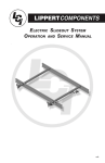
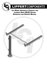
ELECTRIC SLIDEOUT SYSTEM
OPERATION AND SERVICE MANUAL
revA
TABLE
OF
CONTENTS
SYSTEM……………………………………………........….…..3
Warning…………………………………........……....3
Description………………………………........……..3
Prior to Operation…………………….......……… 4
Preventative Maintenance……….......………..4
OPERATION…………………………………........……………5
Warning....................................................5
Extending Slideout Room….......…………. 5
Retracting Slideout Room…….......……... 5
Manual Operation……………….......………. 6
SERVICE…………………………..………………........………9
Adjustment Instructions……….......………….. 9
System Components....................................1 2
Syncronizing System...................................1 4
Replacing Actuator......................................1 5
Troubleshooting…………………….........………1 6
Wiring Diagram…………………….….......………1 9
Ordering Parts…………......………………………2 0
LIMITED WARRANTY………………......……....………….2 1
Warranty Registration.................................2 3
2
SYSTEM
WARNING
FAILURE TO ACT IN ACCORDANCE WITH THE FOLLOWING
MAY RESULT IN SERIOUS PERSONAL INJURY OR DEATH.
The Lippert Electric Slideout System is intended for the
sole purpose of extending and retracting the slideout
room. Its function should not be used for any other
purpose or reason than to actuate the slideout room. To
use the system for any reason other than what it is
designed for may result in damage to the coach and/or
cause serious injury or even death.
Before actuating the system, please keep these things in
mind:
1. Parking locations should be clear of obstructions that
may cause damage when the slideout room is actuated.
2. Be sure all persons are clear of the coach prior to the
slideout room actuation.
3. Keep hands and other body parts away from slideout
mechanisms during actuation. Severe injury or death
may result.
4. To optimize slideout actuation, park coach on solid
and level ground.
Description
The Lippert Electric Slideout System is a rack & pinion guide system,
utilizing an electric ball screw actuator to move the room assembly. The
motor drives the ball screw in a forward and backward motion to drive
the slide room in and out. The actuator comes equipped with an
automatic clutching system. The Lippert Electric Slideout System is
designed to operate as a negative ground system.
3
PRIOR TO OPERATION
Prior to operating the Lippert Electric Slideout System, follow these
guidelines:
1. Coach should be parked on the most level surface available.
2. Leveling or stabilizing system should be actuated to ensure coach will
not move during operation of Slideout System.
3. Be sure battery is fully charged.
4. Be sure to keep all persons and pets clear of Slideout System during
operation.
SYSTEM MAINTENANCE
The Lippert Electric Slideout System has been static tested to over
4,000 continuous cycles with out any noticeable wear to rotating or
sliding parts. It is recommended that when operating in harsh
environments (road salt, ice build up, etc.) the moving parts be kept
clean and can be washed with mild soap and water. No grease or
lubrication is necessary and in some situations may be detrimental to the
environment and long term dependability of the system.
Electrical System Maintenance
For optimum performance, the slide-out system requires full battery
current and voltage. The battery must be maintained at full capacity.
Other than good battery maintenance, check the terminals and other
connections at the battery, the control switch, and the electric actuator
motor for corrosion, and loose or damaged terminals. Check motor
leads under the trailer chassis. Since these connections are subject to
damage from road debris, be sure they are in good condition.
Note: The Lippert Electric Slideout System is designed to operate as a
negative ground system. A negative ground system utilizes the chassis
frame as a ground and an independent ground wire back to battery is
necessary (see page 19 for wiring diagram). It is important that the
electrical components have good wire to chassis contact. To ensure the
best possible ground, a star washer should be used. Over 90% of unit
electrical problems are due to bad ground connections.
Mechanical Maintenance
Although the system is designed to be almost maintenance free, actuate
the room once or twice a month to keep the seals and internal moving
parts lubricated.
Check for any visible signs of external damage after and before
movement of the travel trailer.
NOTE: For long-term storage: It is recommend that the room be closed
(retracted).
4
OPERATION
WARNING
FAILURE TO ACT IN ACCORDANCE WITH THE FOLLOWING
MAY RESULT IN SERIOUS PERSONAL INJURY OR DEATH.
ALWAYS MAKE SURE THAT THE SLIDEOUT ROOM PATH IS CLEAR
OF PEOPLE AND OBJECTS BEFORE AND DURING OPERATION OF
THE SLIDEOUT ROOM.
ALWAYS KEEP AWAY FROM THE SLIDE RAILS WHEN THE ROOM IS
BEING OPERATED. THE GEAR ASSEMBLY MAY PINCH OR CATCH
ON LOOSE CLOTHING CAUSING PERSONAL INJURY.
INSTALL TRANSIT BARS (IF SO EQUIPPED) ON THE SLIDEOUT
ROOM DURING STORAGE AND TRANSPORTATION.
EXTENDING SLIDEOUT ROOM
1. Level the unit.
2. Verify the battery is fully charged and hooked-up to the electrical
system.
3. Remove the transit bars (if so equipped).
4. Press and hold the IN/OUT switch (Fig. 1B) in the OUT position until
the room is fully extended and stops moving.
5. Release the switch, which will lock the room into position.
Note: If the slideout switch is held after the room in fully extended, the
control will sense that the room has stopped and will shut off the motor
after a few seconds.
RETRACTING SLIDEOUT ROOM
1. Verify the battery is fully charged and hooked-up to the electrical
system.
2. Press and hold the IN/OUT switch (Fig. 1C) in the IN position until
the room is fully retracted and stops moving.
3. Release the switch, which will lock the room into position.
NOTE: If the slideout switch is held after the room in fully retracted, the
control will sense that the room has stopped and will shut off the
motor after a few seconds.
4. Install the transit bars (if so equipped).
5
C
B
Fig.1
MANUAL OPERATION
WARNING!
Always disconnect battery from system prior to manually operating system. Failure
to disconnect battery can cause electricity to backfeed through the motor and
cause serious damage to the system as well as void the warranty.
The Lippert Electric slide comes with a manual over ride system. Locate the crank
extension with pin outside of the chassis main rail as, Fig. 2, page 7, shows
underneath the unit on the end of the motor (If your crank extension is under the
inside of the frame, please refer to page 8). This is where the crank handle
(standard fifth wheel landing gear crank handle or 3/4” socket and ratchet fits on to
allow the manual extension/retraction of the room, Fig. 4-5, page 8. Simply take
the crank handle (through-frame models) or wrench, ratchet or drill with a nut driver
(in-frame models) and rotate it clockwise to retract and counterclockwise to
extend slide-out. It is important to note that you DO NOT need to attempt to
disengage the motor as the actuator is “manual ready” Just hook up and crank.
Use EXTREME CAUTION when extending and/or retracting room using the
manual override feature. It is possible to operate the slideout beyond the
maximum extension and/or retraction and damage the slide components, slide
room structure or trim components.
WARNING!
The gears can be stripped out if the room is manually retracted/extended to it’s
fullest extent and the operator continues to rotate manual override.
Any damage due to misuse of the Manual Override feature will disqualify any and
all claims to the Limited Warranty.
6
MANUAL OPERATION - THROUGH FRAME
Through Frame
Crank Extension
w/ pin
Fig. 2
Crank Handle
Fig. 3
7
MANUAL OPERATION - IN FRAME
Motor
Hex Head
Crank Extension
Fig.4
Ratchet
Fig.5
8
SERVICE
MECHANICAL ROOM ADJUSTMENT
Vertical & Horizontal Room Adjustment
NOTE: All slideout room adjustments must be performed by certified
service technicians. Adjustments made by non-certified
persons may void any and all warranty claims.
Horizontal adjustment
1. Loosen 2 carriage bolts “A” on each bracket located at the end
of each guide tube.
2. Room is ready to be positioned horizontally by pushing on the
outside, sidewall or by using a prying devise inserted into the
opening between the room and coach.
Note: Use caution when using prying devise so seals do not become
damaged.
Vertical adjustment
1. Loosen 2 carriage bolts “A” on each bracket located at the end of
each guide tube
2. Loosen jam nut
3. For vertical adjustment turn vertical adjustment bolt “B” up or
down to locate room height.
Once room is located, tighten “A” and Jam Nut bolts.
9
MECHANICAL ROOM ADJUSTMENT
Bolt “A”
Bolt “A”
Fig.6
Jam Nut
Bolt “B”
Fig.7
10
MECHANICAL ROOM ADJUSTMENT-CONT.
Fig.8
Stop Can
Jam Nut-1
Jam Nut-2
Nylock Nut
Adjusting room so it seals in the IN position
1. Locate actuator coming through the frame
2. On the end of the actuator there is a threaded shaft
mounted to the drive bracket with 3 nuts and a stop can.
3. Loosen the ¾” nut (Jam Nut-1) on the outside of the stop
can.
4. Screw the can out or in, and then tighten down the nut – this
will change the location of your seal going to the “in
position”.
Adjusting room so it seals in the OUT position
1. Locate actuator coming through the frame.
2. On the end of the actuator there is a threaded shaft mounted
to the bracket with 3 nuts and a stop can.
3. Move one of the 1” nuts (Jam Nut-2 or Nylock Nut) one way
or the other– this will change the location of your seal going
to the “out position”.
4. Make sure all nuts are tight.
11
12
13
SYNCHRONIZING ROOM TRAVEL
Fig.9
A
B
The Lippert Electric Slideout System room travel (both sides of the room
traveling the same distance) can be adjusted with specially designed
synchronizing bracket mounted on the passive slide tube. The passive
slide tube is the one that is not powered. The active slide tube is the one
that has the cylinder attached. If one side of the room fails to seal adjust
as follows:
1. Loosen bolts (Fig. 9 A) on top of the passive slide
tube (Fig. 9B)
2. Push or pull room (on the passive side) to align with the
active side.
14
REMOVING AND REPLACING ACTUATOR
To replace actuator:
1.
2.
3.
4.
5.
6.
Disconnect manual crank shaft from end of motor assembly (Fig. A).
Disconnect motor wires from source. (Fig. A).
Take measurements A and B (Fig. B).
Remove all jam nuts (3 total) and stop can from threaded shaft on actuator (Fig. B)
Take note of mounting bolt locations and remove mounting bolts (Fig. C).
After everything is disconnected, slide actuator out of frame. To replace with new
actuator, follow previous directions in reverse.
15
TROUBLESHOOTING
The Lippert Electric Slideout System is only one of four interrelated
slideout room system components. These four components are: chassis,
room, coach, and Lippert Electric Slideout System. Each one needs to
function correctly with the others or misalignment problems will occur.
Every travel trailer has its own personality and what may work to fix one
trailer may not work on another even if the symptoms appear to be the
same.
When something restricts room travel, system performance will be
unpredictable. It is very important that slide tubes be free of
contamination and allowed to travel full distance (Stroke). Ice or mud
buildup during travel is an example of some types of contamination that
can occur.
When you begin to troubleshoot the system, make sure the battery is
fully charged, there are no visible signs of external damage to the
actuator or motor and that the motor is wired correctly and all
connections are secure.
You can adjust the room extension with the jam nuts on the end of the
actuator threaded rod (see page 11).
During troubleshooting, remember that if you change something, that
change may affect something else. Be sure any changes you make will
not create a new problem.
You can obtain additional information on the
Lippert Electric Slideout System
by calling 866-524-7821.
16
System Troubleshooting Chart
The following troubleshooting chart outlines some common problems, their causes and possible corrective actions.
When reference is made to “Power Unit” it is referring to the motor and actuator as a complete assembly. All Power
Units are shipped from the factory with a serial number and date code, which should be given to the service
technician when asking for assistance.
ROOM DOESN’T MOVE WHEN SWITCH IS PRESSED
Probable cause
Corrective action
Restrictions both inside and out side unit.
Check for and clear restriction.
Low battery voltage, blown fuse, defective wiring.
Check battery. Charge battery or add auxiliary power source.
Check battery terminals, and all other wiring.
Look for loose/corroded connectors.
Power unit not functioning.
See “Troubleshooting”
on page 5.
POWER UNIT RUNS, BUT ROOM DOES NOT MOVE
Actuator not attached to front mounting
drive bracket.
Check jam nuts/nylock nuts. Be sure that
they are properly tightened and adjusted.
Bad motor or gear housing.
Replace motor.
POWERUNIT RUNS, BUT ROOM MOVES SLOWLY
Low battery, poor ground, extremely
low outdoor temperature.
Room is in a bind.
Charge battery, and check ground wire.
Check to see that room is properly adjusted
ROOM STALLS IN MID TRAVEL
Actuator in a bind.
Crank manual override and move room short
distance then retry electric switch to move room.
Bad actuator.
Replace actuator if above instructions do not work.
NOTES:
·
If the slideout room will not retract there is a manual override that is located on the opposite side of the
slideout room. A crank handle is provided with your unit. Once you have the room in the closed position
take you unit to the closest dealer. See pages 8 & 9.
·
Switch related problems
o
If room moves opposite from what the switch plate indicates, reverse the motor wires on
back of switch (refer to the wiring diagram). Wire size must be 10 GA. Minimum.
o
If you find that you have a stripped gear, replace the gear pack.
o
If the room is out of time / synchronization, refer to pages 10 & 13.
17
TROUBLESHOOTING – MOTOR
Before attempting to troubleshoot the Motor, make sure an adequate
power source is available. The unit batteries should be fully charged or
the unit should be plugged into to A/C service with batteries installed.
Do not attempt to troubleshoot the Motor without assuring a full 12V DC
charge
The following tests require only a DC voltmeter (or DC test light) and a
jumper lead.
Step 1 - Attach voltmeter (or test light) leads to the negative and positive
switch terminals on back of wall switch (See Fig. 10). Does the meter
indicate 12V DC?
If YES, see Step 2; if NO see Step 3.
Step 2 - If YES, at the motor, check the incoming leads to 12V DC (if
necessary, disconnect leads at wire splices). Does meter indicate 12V
DC? If YES, Motor needs to be replaced. The motor is not field
serviceable. DO NOT ATTEMPT TO REPAIR. If NO, Inspect all wires
and connections between the wall switch and the motor. Repair
connections as necessary. Recheck as in Step 1.
Step 3 - If NO, Inspect all connections between battery and switch.
Inspect 30A Auto-reset Circuit Breaker (See Fig. 10 for location).
Recheck as above in Step 1.
Since there are no field serviceable parts in the motor, electrical
troubleshooting and service is limited to replacing only those
components as previously outlined.
Thorough inspection of wiring and connections is the only other electrical
service that can be performed.
18
-
BLACK
RED
MOTOR
MOTOR
GREEN
RED
OUT
IN
SWITCH
BATTERY ( -) WHITE
BATTERY (+) BLACK
BATTERY (-) WHITE
Fig. 10
MOTOR
LOCATE WITHIN 18” OF BATTERY
CAUTION!
HIGH VOLTAGE
Fig.9
CHANGE OF POLARITY
REVERSES MOTOR
BATTERY
+
30A AUTO RESET BREAKER
BATTERY (+)
BATTERY ( -)
WIRING DIAGRAM
19
ORDERING PARTS
To assist the customer service when ordering parts, please provide the
following information:
1. Your Name
2. Company Name
3. Phone Number
4. Shipping Address
5. Billing Address
6. Purchase Order Number
7. Coach
A. Serial # and/or VIN #
B. Make
C. Model
8. Part Number
9. Description
10. Quantity
Please take your coach to an authorized service center for repairs.
Systems that have been modified, adjusted, repaired or augmented by
a party other than an authorized service center may void any warranty
claim with Lippert Components, Inc.
20
LIMITED WARRANTY
THIS WARRANTY EXTENDS ONLY TO THE MERCHANT/ORIGINAL PURCHASER (“Purchaser”)
ACQUIRING THE PRODUCT, AS DEFINED HEREIN, DIRECTLY FROM A LIPPERT COMPONENTS
FACILITY AND SHALL NOT BE CONSTRUED TO EXTEND TO ANY THIRD PARTY, INCLUDING BUT
NOT LIMITED TO THE CONSUMER OR ULTIMATE PURCHASER OF THE END PRODUCT. IN
PART, THE PURPOSE OF THIS PROVISION IS TO REQUIRE THAT ANY AND ALL WARRANTY
CLAIMS BE MADE BY THE MERCHANT/ORIGINAL PURCHASER, AND NOT BY A CONSUMER.
THIS WARRANTY SUPERCEDES ANDY AND ALL PRIOR WARRANTIES.
LIPPERT COMPONENTS warrants the components of it’s Recreational Vehicle Slide-Out System
(“Product”) against defects in materials and workmanship for the following time periods, beginning on
the date of Retail Sale, so long as the Retail Sale occurs within six (6) months of the date Purchaser
acquires the Product directly from a Lippert Components facility:
Three (3) Years – Any ball screw actuator, inner and out tube assembly, rack and gear
assembly, electric motor and cross shaft.
Five (5) Years – Any fluid power components, limited to any hydraulic cylinder and
hydraulic pump.
If a LIPPERT COMPONENTS Product is inspected by an authorized LIPPERT COMPONENTS
representative and is determined to be defective in materials or workmanship within the
aforementioned time period and pursuant to the requirements set forth herein, LIPPERT
COMPONENTS will, in its sole and absolute discretion, do one of the following:
Repair or replace without charge FOB it’s factory;
Send a service team to the then current location of the Product to repair or replace it on
site; or allow credit for the Product.
All warranty claims MUST involve an inspection of the Product and be approved by an authorized
LIPPERT COMPONENTS representative, and all repair procedures must be pre-approved by LIPPERT
COMPONENTS before any repair work can begin. There are no exceptions to this procedure, so
please contact your LIPPERT COMPONENTS division immediately before attempting any repairs or
modifications on your LIPPERT COMPONENTS Product. No claim for Products alleged to be
defective will be allowed until LCI has had a reasonable opportunity to investigate each claim.
This warranty does not cover customer instruction, installation or set up adjustments. Unless otherwise
indicated by tangible evidence, LIPPERT COMPONENTS relies upon the engineering professionals of
those that purchase its Products to design and specify a Product of sufficient size, dimension, strength
and durability to support the structure the Purchaser intends to place upon the Product, and to design
and specify a Product that is sufficient and adequate to function in the role the Purchaser intends to
use and/or produced by its Purchasers and builds Products pursuant to those design specifications.
This warranty does not cover abuse, misuse or neglect, but is not limited to, improper usage,
overloading, accident related damage, improper loading or incorrect weight bias loading, damage
resulting from improper operation or maintenance, connection to improper towing unit or attempted
repair by anyone other than an authorized representative of LIPPERT COMPONENTS. This warranty
does not cover cosmetic damage, damage due to acts of God, commercial use or modification of the
Product, or Products sold AS IS and/or WITH ALL FAULTS. This warranty is valid only in the United
States and Canada.
EXCEPT TO THE EXTENT PROHIBITED BY APPLICABLE LAW, ANY IMPLIED
WARRANTIES OF MERCHANTABILITY OR FITNESS FOR A PARTICULAR PURPOSE
ARE HEREBY DISCLAIMED. REPAIR, REPLACEMENT OR CREDIT AS PROVIDED
UNDER THIS WARRANTY IS THE EXCLUSIVE REMEDY OF THE PURCHASER. IN NO
EVENT WILL LIPPERT COMPONENTS BE LIABLE FOR INCIDENTAL OR
CONSEQUENTIAL DAMAGES.
Claims – All claims are barred unless reported in writing by Purchaser to LIPPERT COMPONENTS,
with full particulars, promptly after the damage was or reasonably should have been discovered and full
facilities are offered LIPPERT COMPONENTS for inspection and investigation. LIPPERT
COMPONENTS will not consider any claims for material that is not in the original form.
21
All written notices required by this warranty shall be sent to:
Lippert Components, Inc.
Attn: Risk Management Department
2375 Tamiani Trail N., Suite 1101
Naples, FL 34103
This warranty is invalid if factory applied identification criteria have been altered or removed from the
Product.
Work performed by others must have the prior authorization of LIPPERT COMPONENTS to be
honored.
Third-Party Events – In the event of any accident, injury to person, damage to property, loss or other
occurrence involving a LIPPERT COMPONENTS Product, Purchaser shall notify LIPPERT
COMPONENTS of such event within thirty (30) days of the event or within ten (10) days of the
notification to Purchaser, whichever is earlier. Notwithstanding the foregoing, Purchaser shall notify
LIPPERT COMPONENTS immediately upon learning that a survey, test or inspection is to be made
with respect to the LIPPERT COMPONENTS Product and provide LIPPERT COMPONENTS with the
opportunity to participate in any such survey, test or inspection, or to permit LIPPERT COMPONENTS
to conduct its own survey, test or inspection. Failure to comply with each of the foregoing shall bar any
claim by the Purchaser against LIPPERT COMPONENTS concerning any such event and shall require
Purchaser to defend, indemnify and hold LIPPERT COMPONENTS harmless from all claims asserted
against LIPPERT COMPONENTS concerning any liability of LIPPERT COMPONENTS arising out of
such event.
Severability – Any legally or otherwise invalid provision hereof shall be considered severable.
Any conditions or exceptions which may be stated in any communication or document received by
LIPPERT COMPONENTS from any entity or individual, including but not limited to the Purchaser, shall
be of no effect unless specifically agreed to in writing by LIPPERT COMPONENTS.
The current warranties and terms outlined on LIPPERT COMPONENTS’ website
(www.lippertcomponents.com) on the date of the purchase shall take precedence over any other
warranties whether verbal or written. LIPPERT COMPONENTS reserves the right to alter its
warranties from time to time, as the laws and the company’s business needs and industry change.
TO THE GREATEST EXTENT PERMITTED BY LAW, ANY CONTROVERSY OR CLAIM ARISING
OUT OF OR IN RELATIONS TO THIS WARRANTY SHALL BE DETERMINED BY BINDING
ARBITRATION IN NAPLES, FLORIDA (COLLIER COUNTY) IN ACCORDANCE WITH THE
COMMERCIAL ARBITRATION RULES OF THE AMERICAN ARBITRATION ASSOCIATION.
PURCHASE OF THE PRODUCT CONSTITUTES PURCHASER’S AGREEMENT TO THIS
PROVISION.
Lippert Electric Slideouts
Lippert Hydraulic Slideouts
Lippert Leveling
Other Lippert Products
Date of Unit Purchase__________/__________/__________
Phone Numbers: Cell(__________)__________-____________________________ Home(__________)__________-_________________________________
_________________________________________________________________________________________________________________________________
(City)
(State)
(ZIP Code)
Address__________________________________________________________________________________________________________________________
(Apt No. or Lot No.)
Owner Name______________________________________________________________________________________________________________________
Check ALL that apply:
Date of Unit Manufacture__________/__________/__________
_________________________________________________________________________________________________________________________________
(VIN Number)
(Number of Slideouts)
RV Description____________________________________________________________________________________________________________________
(Manufacturer)
(Model)
(Year)
Lippert Components, Inc. - Plant #39
Attn: Service and Warranty
2703 College Ave.
Goshen, IN 46528
Call us toll free at: (866) 524-7821
Find us on the web: http//www.lci1.com/warranty.html
Attention Purchaser: Please fill out form as completely as possible, detach at the dashed line above and mail this card to Lippert Components, Inc. at the
following address within 30 days of the retail purchase date of your unit to activate the warranty of this product.
Warranty Registration Card
(-------------------------------------------------------------------------------------------Lippert Components, Inc.