1
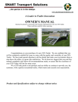
Service Manual 200 Series 36V 15312 Table of Contents Section 1 - General Information ............................................ 1 Model Identification....................................................................1 Frame Number ................................................................... 1 Specifications .............................................................................1 Section 2 - Maintenance ......................................................... 2 Periodic Checks and Services ......................................................2 Maintenance and Tune-Up Procedures ........................................2 Tire Pressure / Wear ........................................................... 2 Brake Fluid and Performance ............................................... 3 Chassis Nuts and Bolts ........................................................ 3 Chassis Lubrication ............................................................. 3 Belt Tension ....................................................................... 4 Motor ................................................................................. 4 Batteries ............................................................................ 4 Section 3 - Motor and Controller ............................................ 4 Motor removal and Installation ...................................................4 Motor Removal ................................................................... 4 Motor Installation ............................................................... 5 Controller Removal and Installation .............................................5 Controller Removal ............................................................. 5 Controller Installation .......................................................... 5 Section 4 - Drive System ........................................................ 5 Belt Tensioning and Replacement ...............................................5 Belt Tensioning ................................................................... 5 Primary Belt Replacement ................................................... 6 Secondary Belt Replacement ............................................... 6 Section 5 - Throttle ................................................................ 7 Throttle Installation and Adjustment ...........................................7 Throttle Assembly Removal ................................................. 7 Throttle Sensor Removal ..................................................... 7 Throttle Safety Switch Removal ........................................... 7 Throttle Safety Switch Installation........................................ 7 200 Series 36V 15312 Throttle Sensor Installation ................................................. 7 Throttle Assembly Installation .............................................. 8 Section 6 - Electrical System .................................................. 9 Schematics ................................................................................9 Batteries .................................................................................. 11 Testing and Water Level..................................................... 11 Replacement ..................................................................... 11 Charging ........................................................................... 13 Battery Indicator ................................................................ 13 Section 7 - Chassis ............................................................... 14 Steering Alignment................................................................... 14 Section 8 - Brakes ................................................................ 15 Brake System Replacement ...................................................... 15 Section 9 - Troubleshooting ................................................. 16 Flowchart ................................................................................ 16 Procedures .............................................................................. 17 Throttle Harness: Throttle Sensor / Potentiometer Signal ..... 17 Throttle Harness: Throttle Switch Signal .............................. 17 Throttle Position Sensor / Potentiometer ............................. 18 Throttle Switch .................................................................. 19 12V Power......................................................................... 20 Power Checks: 12V ............................................................ 20 Battery Checks: Individual Battery ...................................... 21 Battery Checks: Battery System .......................................... 21 Power to Throttle Switch .................................................... 22 Controller Power from 36V Harness .................................... 22 Relay ................................................................................ 23 Power Checks: 36 V ........................................................... 24 Power to Small Posts of Contactor ...................................... 25 Controller Power Through Contactor ................................... 26 Resistor............................................................................. 27 Controller Evaluation .......................................................... 27 15312 200 Series 36V Section 1 -GENERAL INFORMATION MODEL IDENTIFICATION Frame Number The frame number or VIN can be found on a plate, which is located on the crossbar, behind the seats. VIN Number SPECIFICATIONS DIMENSIONS Overall Length --------------------------------------------------- 2502mm(98.5inch) Overall width ------------------------------------------------------ 1245mm (49inch) Overall height --------------------------------------------------- 1765mm (69.5inch) Wheelbase ------------------------------------------------------- 1500mm (59.0inch) Track Width – Front / Rear -------- 1160mm (47.7inch) / 1000mm (39.4inch) Ground Clearance ------------------------------------------------- 170mm (6.7inch) PERFORMANCE Motor Type ------------------------------------------------ 36V 300A Electric SepEx Output Power / Torque --------------- 9.9 hp @7500rpm / 13ft-lbs @ 5500rpm Starting ------------------------------------------------------------------ Keyed Electric Transmission ------------------------------------------------------- Double Belt Drive Top Speed ----------------------------------------------------------------------- 20mph CAPACITIES Maximum Load (Driver, Passenger, & Gear) ------------------------------- 650lbs Climbing Angle ------------------------------------------------------------------ 20-25 Batteries -----------------------------------------------------12V Golf Car 155Ah (3) Head Lights ---------------------------------------------------------------12V 35W (2) Tail Light --------------------------------------------------------------- 12V 21W / 5W CHASSIS Brakes (Front and Rear) --------------------------Hydraulic disc/Left foot control Tires – Front / Rear ------------------- 20 x 7.0-8 @ 15psi / 22×11-10 @ 15psi Page 1 200 Series 36V 15312 Suspension-Front ------------------------ Dual A-arm with 1.8” (45mm) of travel Suspension-Rear ----------------- Spring over shock with 2.4”(60mm) of travel WEIGHT Dry Weight ------------------------------------------------------------ 408Kg / 975lbs WARRANTY Components -------------------------------------------------------------------- 30 days Frame --------------------------------------------------------------------------- 90 days Motor and Controller ----------------------------------------------------------- 1 year * The specifications are subject to change without notice. Section 2 -MAINTENANCE PERIODIC CHECKS AND SERVICES The maintenance intervals in the following table are based upon average riding conditions. Riding in unusually dusty or muddy areas require more frequent servicing. Interval Initial service (first week) Monthly Tire Pressure / Wear (p. 2) I I Brake Fluid and Performance (p. 3) I I Chassis Nuts and Bolts (p. 3) I I Chassis Lubrication (p. 3) Belt Tension (p. 4) I Motor (p. 4) Batteries (p. 4) Quarterly C, I L I C, A Yearly C, I I C, I, A A: adjust C: clean I: inspect, clean or replace if necessary. L: lubricate R: replace MAINTENANCE AND TUNE-UP PROCEDURES This section describes the servicing procedures for each item in the Periodic Maintenance requirements. Tire Pressure / Wear Check the tire pressure every time the kart is ridden. The tire pressure is very important for the stability of the ride. 15312 200 Series 36V For proper tire pressure ratings, see Section 1 -Specifications. Brake Fluid and Performance Always check that there is plenty of brake fluid in the brake fluid reservoir. Ensure brake fluid looks clean and brake hoses are in good condition Check that the front (7150 only) and rear brake pads are in good condition. Check the brake rotors for abnormal wear. Chassis Nuts and Bolts Always pay attention to the karts nuts and bolts. Some loosening after use is normal and should not be left unchecked for an extended period of time. TIGHTENING TORQUE CHART Conventional marked bolt 8.8 marked bolt Bolt Diameter (mm) N.m Kg.m Ib-ft N.m Kg.m Ib-ft 4 1 ~2 0.1 ~0.2 0.7 ~1.5 1.5 ~3 0.15 ~0.3 1.0 ~2.0 5 1 ~4 0.2 ~0.4 1.5 ~3.0 3 ~6 0.3 ~0.6 2.0 ~4.5 6 4 ~7 0.4 ~0.7 3.0 ~5.0 8 ~12 0.8~1.2 6.0 ~8.5 8 10 ~16 1.0 ~1.6 7.0 ~11.5 18 ~28 1.8 ~2.8 13.0 ~20.0 10 22 ~35 2.2 ~3.5 16.0~25.5 40 ~60 4.0 ~6.0 29.0 ~43.5 12 35 ~50 3.5 ~5.5 25.5 ~40 70 ~100 7.0 ~10.0 50.5 ~72.5 14 50 ~80 5.0 ~8.0 36.5 ~58 110 ~160 11.0 ~16.0 79.5 ~115.5 16 80 ~130 8.0 ~13.0 58 ~94 170 ~250 17.0 ~25. 123.0 ~181.0 18 130 ~190 13.0~19.0 94 ~137.5 200 ~280 20 ~28.0 144.5 ~202.5 Chassis Lubrication Clean and Grease chassis bushings and bearings quarterly to assure smooth operation and extended life of the bushings and the components. If used in extreme wet and muddy conditions or dusty conditions, it is recommended more often. Page 3 200 Series 36V 15312 Inspect components for cracks or abnormal or excessive wear. Belt Tension Inspect and adjust belt tension. Refer to Section 4 --Drive System for details. Motor Inspect electrical connections to the motor. Tighten loose connections as specified in Section 3 -Motor removal and Installation. Inspect motor mounting bolt tension and condition of insulating washers. Clean motor with soapy water to allow proper cooling. Batteries Clean surfaces of batteries with a solution of water and baking soda. Inspect for damage or excessive leaking. Inspect nut tension and the condition of the cables. If any signs of arching or wear exist, adjust or replace the affected component. Loose connections in the battery system can cause serious damage to the vehicle’s electrical system. Inspect water level of each cell of each battery. See Section 6 - 15312 200 Series 36V Batteries. Section 3 -MOTOR AND CONTROLLER Before servicing the Motor or Motor Controller, be sure to disconnect the Main Fuse. A charge is stored in the Motor Controller and if its terminals are shorted out, even though disconnected from the battery, it may spark. This will not cause damage to the controller. MOTOR REMOVAL AND INSTALLATION The motor is isolated from the chassis to ensure arching will not damage the motor controller. Ensure isolating washers are put back in place after removal. Motor Removal To remove the motor: 1. 2. 3. 4. Disconnect the Main Fuse. Using a 2.5mm Allen Wrench, loosen the drive pulley set screw. Loosen the Drive Belt Tensioner to allow excess play in the belt. Remove bottom bolts from motor, attaching it to the mounting plate, then remove the upper bolts. Notice the order of washers as the bolts are removed. 5. Carefully pull the motor away from the mounting plate, allowing the drive pulley to slide off the motor shaft. Motor Installation To install the motor: 1. 2. 3. 4. 5. 6. 7. First, install the isolating washers and bolts into the motor mounting plate. Align motor and install bolts. Place key in keyway of motor shaft. Fit drive pulley into belt and install onto motor shaft. Center the drive pulley with the secondary pulley. Apply removable thread lock to the threads of the drive pulley set screw. Using 2.5mm Allen Wrench, tighten the set screw CONTROLLER REMOVAL AND INSTALLATION Controller Removal 1. 2. 3. 4. Disconnect the Main Fuse. Remove the three bolts holding the controller to the mounting plate. Disconnect the two motor Field connections (F+ and F-). Using a 6mm Allen Wrench, remove the three motor Armature and Ground connections (M+, M-, and B-). Page 5 200 Series 36V 15312 Controller Installation 1. Using a 6mm Allen Wrench, connect the three motor Armature and Ground connections (M+, M-, and B-). 2. Connect the two motor Field connections (F+ and F-). 3. Install the three bolts that hold the controller to the mounting plate. Section 4 -DRIVE SYSTEM Before servicing the belt or other drive components, ensure the vehicle power is OFF and the wheels are chocked. Fingers or other body parts can get severely injured by moving drive components. BELT TENSIONING AND REPLACEMENT Belt Tensioning Adjust both the primary and secondary belts to 1/2” flex. Do NOT over tighten, as this will cause premature belt wear and excessive drive noise. 1. Unlock the tensioner by loosening the smaller 3/8” tensioner bolt. 2. Insert a 3/8” socket wrench into the tensioner, set to loosen (counterclockwise). 3. Apply a small amount of pressure to the socket wrench until there is approximately 1/2” flex in the belt. 4. Tighten the smaller 3/8” tensioner bolt to lock the tensioner in place. It is not necessary to tighten the center nut on the tensioner, but it may be tightened if desired or if tensioner slip is occurring. Primary Belt Replacement Primary belt replacement requires disassembly of the jackshaft components. When attempting to loosen or tighten jackshaft nuts, stay clear of all belt-driven components, as they may rotate during this process. Before servicing, chock the rear wheels of the vehicle. 1. 2. 3. 4. 5. Remove the guard above the pulleys. Loosen the primary belt tensioner by loosening the smaller 3/8” bolt. Remove the nut from the left side of jackshaft Slide jackshaft toward right side until the tall pulley is free to be removed. Remove pulley and replace with new belt attached, starting with the belt around the smaller drive pulley on the motor shaft. 6. Line up pulley with keyway on the jackshaft and slide the jackshaft left, through the spacer and bearing. 15312 200 Series 36V 7. Install and tighten jackshaft nut until there is no horizontal play in the pulleys (approx. 90 – 110 ft-lbs). 8. Tension the belt following the instructions found in Section 4 -Belt Tensioning. 9. Replace guard removed in step 1. Secondary Belt Replacement Secondary belt replacement requires disassembly of the jackshaft components. When attempting to loosen or tighten jackshaft nuts, stay clear of all belt-driven components, as they may rotate during this process. 1. Jack the vehicle’s swingarm and place on jack stands to keep the rear wheels off the ground. Do NOT use the Axle as a jack point. 2. Remove left rear tire/wheel 3. Remove the guard above the pulleys. 4. Loosen the secondary belt tensioner’s smaller 3/8” bolt. 5. Loosen left rear axle bearing flange and slide bearing assembly to the left. 6. Remove the right jackshaft nut. 7. Slide the jackshaft to the left until the wide pulley is free to be removed. 8. Remove secondary drive belt by sliding it off of its pulley, down the axle shaft to the left, through the slot of the swingarm axle bracket, and then off the axle. 9. Install the new belt by sliding it over the axle, through the slot of the swingarm axle bracket, and placing it over the axle pulley. 10. Place loose pulley inside the belt. 11. Line up pulley with keyway on the jackshaft and slide the jackshaft right, through the spacer and bearing. 12. Install and tighten jackshaft nut until there is no horizontal play in the pulleys (approx. 90 – 110 ft-lbs). 13. Replace guard removed in step 3. 14. Tension the belt following the instructions found in Section 4 -Belt Tensioning. 15. Reinstall the left rear tire/wheel. 16. Raise vehicle slightly and remove jack stands and lower vehicle. Section 5 -THROTTLE Proper installation and adjustment of the throttle assembly will ensure safe and reliable control. Improper adjustment could result in undesirable results, such as a sticking throttle pedal or lack of functionality. Follow the instructions below. THROTTLE INSTALLATION AND ADJUSTMENT Before working on the throttle assembly, ensure the key switch is in the OFF position. Page 7 200 Series 36V 15312 The following instructions include replacement of the sensor, switch, and bracket. Throttle Assembly Removal 1. 2. 3. 4. 5. Disconnect throttle sensor and safety switch. Unhook the throttle spring from the throttle bracket. Loosen the throttle bracket adjustment screw. Remove the throttle pedal bolt. Remove throttle assembly. Throttle Sensor Removal 6. Using pliers, carefully remove the throttle sensor clip. Throttle Safety Switch Removal 7. Remove the two nuts holding the switch in place. Throttle Safety Switch Installation 8. Align the two holes on the safety switch with the holes in the throttle bracket. 9. Install both mounting bolts and locking nuts. Throttle Sensor Installation 10. Align sensor and clip with holes in throttle bracket. Outward force may be applied to the clip to align with the holes. 11. Carefully apply even pressure on the clip to insert it into the holes. The sensor can get damaged if care is not taken here. The sensor may have some play between the bracket and clip. This is normal. Throttle Assembly Installation 12. Install the throttle pedal bolt through the throttle components as shown below. 13. Verify the throttle pedal is free to move and is not bound. 14. Tighten the nut for the throttle pedal bolt. 15. Again, verify the throttle pedal is free to move. 16. Connect the throttle spring, starting with the throttle pedal, then the throttle bracket. 17. Connect the wires and connector to the sensor and switch. 18. Follow the test procedures in section Section 9 -Procedures to verify the correct signals are at the motor controller. 19. With the seatbelt properly fastened, attempt to drive the vehicle slowly to ensure proper functionality of the throttle circuit. 15312 200 Series 36V Section 6 -ELECTRICAL SYSTEM SCHEMATICS Figure 1 Vehicle Schematic Page 9 200 Series 36V 15312 Figure 2 Motor Controller Schematic 15312 200 Series 36V BATTERIES Batteries contain acid that can be harmful. Therefore, special care must be taken when handling. Testing and Water Level Each battery should measure at least 12.8V fully charged. Before charging, ensure the water level for each cell of the batteries is at least slightly above the plates as shown below. If any battery cannot be charged to this level, ensure the water level is where it should be, per the instructions below. If the water level is good and the battery(ies) still will not hold 12.8V or higher, check the specific gravity for each cell. 1. Open the vent caps and look inside the fill wells. 2. Check electrolyte level; the minimum level is at the top of the plates. Water level above this point before charging. 3. If necessary add just enough water to cover the plates at this time and replace the vent caps. 4. Put batteries on a complete charge before adding any additional water (refer to Raise vehicle slightly and remove jack stands and lower vehicle. 5. Charging below). 6. Once charging is completed, open the vent caps and look inside the fill wells. 7. Add water until the electrolyte level is 1/8" below the bottom of the fill well. 8. A piece of rubber can be used safely as a dipstick to help determine this level. 9. Clean, replace, and tighten all vent caps. Replacement Each battery in the system should be the same make and model. Replacing a battery with one of a different rating may hinder vehicle performance and fail prematurely. To remove one or more batteries: Page 11 200 Series 36V 15312 1. Jack the vehicle’s swingarm and place on jack stands to keep the rear wheels off the ground. Do NOT use the Axle as a jack point. 2. Remove one of the rear wheel assemblies to give access to the preferred side or removal. 3. Disconnect Main Fuse. 4. Disconnect battery wiring to all batteries. 5. Remove battery hold down nuts located underneath the battery rack. 6. Remove battery hold down. 7. Slide end battery out and remove from system. NOTE the orientation of the battery as it is removed. Repeat for all others to be replaced. To install one or more batteries: 8. Slide battery into place, keeping its orientation correct, as shown here: 9. Install battery hold down. 10. Install battery hold down nuts. 11. Install wiring to batteries and Main Fuse as shown here: 12. Torque battery nuts to 8~10 ft-lbs (96~120 in-lbs). 13. Double-check all wiring, nuts, and battery orientation. 15312 200 Series 36V 14. Connect Main Fuse. 15. Turn ON the key and check that throttle functions properly. 16. Reinstall wheel assembly. 17. Raise vehicle slightly and remove jack stands and lower vehicle. Charging The included onboard NOCO Genius charger is a complete charger and maintainer package. It charges and maintains each battery individually. Charging starts soon after the charger is plugged in. A slight spark when first plugged in is normal. For the first minute after the charger is plugged in, a series of checks is performed to ensure it is safe to charge the batteries. After a minute or so, charging begins at up to 10A per battery. From this point on, the charger constantly monitors the battery state of charge to determine which of the 7 charging steps are most appropriate. A red light indicates the battery is being charged. Green indicates the charger is in the final stage of charge and is at least 90% charged. Over the next 2 hours or so, the battery is “topped-off”. It is okay to use the vehicle once the chargers indicators are all green. Overall, this process can take up to 12 hours. The charger is able to detect a battery is connected all the way down to 2V. If the battery voltage is below 2V, the charger will flash Red/Green. In this case, another source can be used to “jump” the battery so charging can begin. With the charger plugged in, connect another external source, such as a 12V “dumb” charger or a separate 12V battery to the terminals of the low voltage battery for a moment, until the charge indicator changes from flashing Red/Green to solid Red. Remove the external source as soon as the light is solid Red. Flashing Red/Green lights also indicates an open battery circuit between the charger and respective battery. Check for a broken connection/wire. Lastly, flashing Red/Green can indicate charging cannot be completed on the respective battery. If at any point during the charge cycle a problem is detected with the battery, charging will stop and the lights will flash Red/Green. This includes if charging cannot complete in a 1 hour period. If left plugged in, as a maintenance charger, the charger will check the state of charge on the batteries every 24 hours. If detected that the battery voltage has dropped around 20% or more, charging will start over at the finishing stages of charge. It is recommended that the charger remain plugged in as long as the vehicle is not in use, including winter months or in storage. Battery Indicator Located in the dash is a battery discharge meter. This is driven by the 12V battery which drives the entire 12V electrical system. If a problem is suspected with the batteries not attached to this meter, the charger should indicate this during the charge cycle by flashing Red/Green at any point along the charge Page 13 200 Series 36V 15312 cycle. The indicator is meant to provide the condition of the “typically” lowest charged battery in the group. Typically, the indicator will show empty (alternating red lights) well before the vehicle cannot fully operate. It is okay to operate the vehicle until it slows due to low voltage, but is recommended to be charged whenever the gauge shows empty. This will provide the best life of the batteries. It is normal for the discharge meter to not show an increase in voltage level until charging has completed. Battery voltage must be greater than 14.1V for a minimum of 7 minutes for the gauge to reset. All digital battery indicators have this characteristic to prevent the gauge from indicating a voltage that is not relevant. As batteries sit unused, the voltage may creep up, but the useable potential of the batteries is not there. If the discharge meter is not resetting to full, the charger should also be indicating a problem on the respective battery. Section 7 -CHASSIS STEERING ALIGNMENT For best off-road performance, the steering alignment should be set “toed-in” as shown here: The front wheel should be “toed-in” 1/8” to 1/4". To check alignment measure distance from A to B to the centerline (CL) of the tires with the wheels point straight ahead. For the proper toe-in dimension A should be 1/8 ~1/4" greater than dimension B. Loosen the locknuts on both sides of Front Tie Rods. To Make Dimension B smaller, screw the rod left. If B needs to be longer screw the rod right. Tighten the jam nut tightly against the rod end. Recheck the distance and repeat the above steps until the Dimensions are per paragraph 1 above. 15312 200 Series 36V Section 8 -BRAKES BRAKE SYSTEM REPLACEMENT Page 15 200 Series 36V 15312 Section 9 -TROUBLESHOOTING FLOWCHART Follow the steps below to quickly diagnose common issues. For detailed testing information, see Procedures below. It is strongly recommended to first check all wiring connections and terminals to ensure that they are securely attached. Loose connections are the most common cause for electrical issues. Issue Test Item Vehicle does not move when throttle depressed Turn Key Switch ON Having the throttle depressed while shifting from “F” to “R” or visa-versa will generate a fault. Battery Gauge turns ON Relay “clicks” once Check connections at Relay Ensure 12V at Black wire when key ON >36V at Orange Contactor wires Touch Pre-charge Resistor. If hot, Reset Key Switch to resolve the fault. If Fail Check Main Fuse Check 12V circuit Fuse Check Yellow Body connector Check for >12V at Key Switch Red and Black on harness side controller is bad. Disconnect Main Fuse. Check 36V circuit Fuse Check for >36V at Purple wires at Motor Controller Check condition or all other connections at controller Turn Key Switch OFF 15312 Throttle Switch continuity to Ground with Throttle depressed (white wire at controller) Check connections at Throttle Switch Throttle Sensor resistance normally below 120Ω (Gray to Gray/Black wires at controller) Check that Throttle Pedal has fully Throttle Sensor resistance above 4300Ω when Throttle depressed (Gray to Gray/Black wires at controller) Check condition of connections at returned Inspect Throttle sensor closely for cracks Throttle Sensor Check connection to harness 200 Series 36V Vehicle will not go in Reverse Turn Key Switch OFF Connections at F/R Switch are good F/R Switch continuity while “R” is selected (Blue to Blue/Yellow wires at controller) Check connections at controller PROCEDURES Throttle Harness: Throttle Sensor / Potentiometer Signal Confirm that the throttle position sensor signal is making it to the controller. Remove the 5-pin connector from the controller. There will be three wires in it. Use “Ω” setting on the meter. Place one probe on the end of the gray wire and one on the end of the gray wire with the black stripe. With plunger extended (throttle returned), the resistance should be less than 160 Ohms (Ω). Depress plunger by pressing down on the throttle pedal. With the throttle fully depressed, the resistance should be at least 4,300 Ohms (Ω) or 4.3KΩ. If this test result is good, the throttle position sensor is also good and does not need tested as an individual component. Throttle Harness Controller Throttle Harness Throttle Harness: Throttle Switch Signal Confirm that the throttle switch signal is making it to the controller. Page 17 200 Series 36V 15312 Remove the 5-pin connector from the controller. There will be three wires in it. The throttle switch is an ON/OFF switch. Use “Ω” setting on the meter. Place one probe on the white wire and one on the chassis ground. With the button pushed in (throttle fully returned) the meter should say “OL”. With the button extended (throttle pressed), there should be a value shown close to Zero Ohms (0Ω). If this test result is good, the throttle switch is also good and does not need tested as an individual component. Throttle Harness Probe Placement for Throttle Harness Testing of Safety Switch Signal Nearest Chassis Ground Throttle Position Sensor / Potentiometer 15312 Use “Ω” setting on the meter. Unplug the throttle position sensor from the harness. Place one probe on the end of each wire. With plunger extended (throttle returned), the resistance should be less than 160 Ohms (Ω). Depress plunger by pressing down on the throttle pedal. With the throttle fully depressed, the resistance should be at least 4,300 Ohms (Ω) or 4.3KΩ. If this does not happen, replace the sensor. 200 Series 36V Throttle Position Sensor Probe Placement >4.3 KΩ with throttle depressed <160 Ω with throttle returned Throttle Switch The throttle switch is an ON/OFF switch. Use “Ω” setting on the meter. Remove the throttle harness connectors. Place one probe on each spade terminal on the Switch. With the button pushed in (throttle fully returned) the meter should say “OL”. With the button extended (throttle pressed), there should be a value shown close to Zero Ohms (0Ω). If this does not happen, replace the switch. Page 19 200 Series 36V 15312 Safety Switch Probe Placement Complete circuit with throttle pressed Open circuit with throttle returned 12V Power With ignition key “ON” check to make certain that the battery indicator and headlights are functional. Power Checks: 12V 15312 If there is no 12 volt power, check the main 350 amp fuse and chassis harness fuse. Check fuse first by looking at the piece of metal that runs through the glass. If it is broken, replace the fuse. If it appears to be intact, confirm with the meter by setting on the meter to “Ω” and placing a probe on each end of the fuse. The meter should give a value close to Zero Ohms (0Ω). “OL” displayed will represent a blown fuse. If still no power, check all connections (pins, wires, locations) same as you would for the models with gas engines. o Chassis harness yellow plug (inserted fully). o Relay plug (Blue or Black automotive relay). o The dash panel harness, especially the “bullet” connectors (make sure they are tight) and the spade connectors (make sure they are properly installed) o ALL pins at ALL connectors of ALL harnesses are properly installed and in the correct positions. o Check all splices in the harness. All connectors are fully inserted into the controller. Confirm that batteries are wired correctly. Check continuity of all wires and cables. Confirm with the meter by setting on the meter to “Ω” and placing a probe on each end of the wire/cable. The meter should give a value close to Zero Ohms (0Ω). “OL” displayed will represent a broken wire. 200 Series 36V 12V Fuse Chassis Harness Main Fuse Yellow Connector Battery Checks: Individual Battery Use “V” setting on the meter. Place one probe on the positive (+) post and one on the negative (-) post of a given battery. It should read greater than 12 volts on each battery. >12 volts for an individual battery Probe Placement Battery Checks: Battery System Use “V” setting on the meter. Place one probe on the negative (-) post at the 350 amp fuse. Place the other on the positive cable going to the contactor. It should read greater than 36 volts. Page 21 200 Series 36V 15312 If it does not, check to be certain that the 36 volt circuit is wired properly. To contactor (+) Probe Placement (-) Probe Placement Main Fuse >36 volts for the battery system Power to Throttle Switch Use “V” setting on the meter. Place one probe on the white wire of the Throttle switch and one probe to a good chassis ground such as the negative (-) post at the 350 amp fuse. Turn the ignition key to the “ON” position. The meter should read 12 – 14 volts. Safety Switch (+) probe placement shown (-) probe placement to any good chassis ground Meter Result 12 - 14V Controller Power from 36V Harness 15312 Use “V” setting on the meter. 200 Series 36V Place one probe on one of the three purple wires and one probe to a good chassis ground. Turn the ignition key to the “ON” position. The meter should read in excess of 36 volts. Repeat for the other purple wires. All purple wires are tied together. If one is not getting power and the others are, a bad crimp or broken wire may be the problem. 10-Pin Connector with 1 power feed (purple wire) Controller (-) probe placement options 4-Pin Connector with 2 power feeds (purple wires) (+) probe placement and meter result Action If the proper voltage is not present, check all connections and splices in the 36 volt harness and repair as necessary. Wiring must be traced to locate the item that is disrupting the circuit. Relay Make sure it makes a faint “click” when the key is powered ON and again when key is OFF. If the “click” is not present, check the wiring to the relay. With the Key ON, verify 12V exists between at the black connection. If 12V exists and Relay does not click, replace the relay. Page 23 200 Series 36V 15312 Relay (Blue or Black) Power Checks: 36 V If there is no 36 volt power, check the main 350 amp fuse and the 36 volt harness fuse. Check fuses first by looking at the piece of metal that runs through the glass. If it is broken, replace the fuse. If it appears to be intact, confirm with the meter by setting on the meter to “Ω” and placing a probe on each end of the fuse. The meter should give a value close to Zero Ohms (0Ω). “OL” displayed will represent a blown fuse. If still no power, check all connections (pins, wires, locations) same as you would for the models with gas engines. o Relay plug (Blue or Black automotive relay). o ALL pins at ALL connectors of ALL harnesses are properly installed and in the correct positions. o Check all splices in the harness All connectors are fully inserted into the controller. Check continuity of all wires and cables. Confirm with the meter by setting on the meter to “Ω” and placing a probe on each end of the wire/cable. The meter should give a value close to Zero Ohms (0Ω). “OL” displayed will represent a broken wire. 36V Fuse 12V Fuse Main Fuse 15312 200 Series 36V Power to Small Posts of Contactor Use “V” setting on the meter. Place the RED probe on the small stud of the contactor, with the orange wire, and the BLACK probe to a good chassis ground such as the negative (-) post at the 350 amp fuse. Turn the ignition key to the “ON” position. The meter should read at least 36 volts. Contactor One (+) probe placement shown (+) probe placement to either small post with the orange wire (either small post with an orange wire is acceptable) (-) probe placement to any good chassis ground Meter Result > 36V Page 25 200 Series 36V 15312 Controller Power Through Contactor Use “V” setting on the meter. Make certain that the resistor has been re-installed if it was disconnected in a previous test. Place the black probe to a good chassis ground such as the negative (-) post at the 350 amp fuse or where the ground cable attaches to the frame. Place the other at the controller’s “B +” position on the cable coming from the contactor. It should read approximately 30 volts. B + terminal (Farthest rearward and only terminal with both a red and black cable attached) (+) probe placement B+ Terminal Controller (-) probe placement Main Fuse Meter Result Approximately 30V Action If the required voltage is not present, wiring must be traced to locate the item that is disrupting the circuit. Additionally, check for a hot resistor across the Contactor. This indicates a failed controller. 15312 200 Series 36V Resistor Remove the resistor from one post of the contactor. The side that is powered from the battery is recommended. Use “Ω” setting on the meter. Place one probe on the free end of the resistor and one on the other post. The reading should be approximately 680 ohms. If this does not happen, replace the resistor. To Controller Contactor (-) Probe Placement Resistor Removed from this Post (+) Probe Placement and Resistance Reading Note: Additionally, a hot resistor across the Contactor indicates a failed controller. Controller Evaluation If it is suspected that the motor controller is bad, perform these checks before replacing. Page 27 200 Series 36V 15312 Measuring from M- to B- will be around 18.25KΩ. From M- to B+ will start around 18.25KΩ and charge up as the meter is connected. Measuring from F+ to F- will be around 9MΩ 15312 200 Series 36V