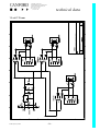
1
CANFORD AUDIO PLC
CROWTHER ROAD WASHINGTON
TYNE & WEAR NE38 OBW, UK
admin (0191)418 1000
sales (0191)418 1122
fax (0191)418 1001
technical data
MINX MIXER
SERVICE MANUAL
Manufactured by Canford Audio plc
Under licence from Audio Systems Components Ltd
02-405 (Issue 2) 02/03
CANFORD AUDIO PLC
CROWTHER ROAD WASHINGTON
TYNE & WEAR NE38 OBW, UK
admin (0191)418 1000
sales (0191)418 1122
fax (0191)418 1001
technical data
CONTENTS
Introduction
3
Application Notes
3
Operating Instructions
Front Panel
- Input Level
- Pre-fade listen (PFL)
- High Pass Filter
- Headphone Monitoring
- Talkback Routing (PTT)
- Limiter
- Battery Check
- PPM
- Headphone level
- Oscillator
Back Panel
- Input Selector
- Control Line Input
- Mixer Output
- Output Attenuator
- Battery Switch
-IEC Mains Socket
- Fuse Holder
- Headphone sockets
- Battery Compartment
6
6
6
6
6
6
7
7
7
Phantom Power module
Phantom Power (obsolete version)
7
8
4
4
4
4
4
5
5
5
5
5
Technical Specification
9 & 10
Circuit Diagrams
- Schematic
- Channel 1
- Channel 2
- Channel 3
- Mix amp/Limiter/Output amp
- Pre-fade Listen
- PPM Driver
- Regulated Power Supply
- Sub Board
- 12 volt T-power
11
12
13
14
15
16
17
18
19
20
Notes
02-405 (Issue 2) 02/03
21
-2-
CANFORD AUDIO PLC
CROWTHER ROAD WASHINGTON
TYNE & WEAR NE38 OBW, UK
admin (0191)418 1000
sales (0191)418 1122
fax (0191)418 1001
technical data
INTRODUCTION
Thank you for choosing the Minx mini mixer.
A lot of care and attention has gone into the design and build of this product and we hope that it will serve
you well. Like any technology product the only way to get the best from it is to thoroughly read and
understand the manual.
Should you find any aspect of this product and its related documentation ambiguous or confusing please
let us know.
Additionally, should you perceive ways in which the Minx could be improved we would welcome your
comments.
APPLICATION NOTES
The Minx was designed to be for 2 man operation, nominally presenter (DJ) and engineer. The presenter
need not necessarily be next to the engineer as talkback exists from engineer to presenter; also the
engineer/presenter can talk back two -way with base on the CUE line.
Typical uses are:
Sports Events
Mics for presenter, actuality and guest.
Town Hall
Expanding existing mic positions at debates etc.
Live OBs
Less than 6lb in weight and battery powered the Minx
can feed radio links (remote pickup) or radio mics at mic level.
These are just typical uses. The Minx is so compact and versatile, yet with such good quality specs.
it can be used as a sub-mixer at concerts, feed ENG cameras/VCRs or for local work.
02-405 (Issue 2) 02/03
-3-
CANFORD AUDIO PLC
CROWTHER ROAD WASHINGTON
TYNE & WEAR NE38 OBW, UK
admin (0191)418 1000
sales (0191)418 1122
fax (0191)418 1001
technical data
FRONT PANEL CONTROLS
1. Input Level Control
A dual-concentric pot. arrangement feeding the mix bus where the back (outer) knob adjusts GAIN and the
front (inner) knob acts as a FADER. Level set by the GAIN control is progressively attenuated by the
FADER control by adjusting FADER anti-clockwise from the fully open(clockwise) position. The
FADER control, therefore, does not contribute any more gain i.e. does not have (say) 10dB in hand.
2. Pre-Fade Listen (PFL)
When selected, as indicated by the orange iris, allows monitoring of this (and any other channel currently
in PFL mode) or engineer's (1 ENG.) headphones only. FADER (see Section 1) is not operative and
channels with PFL selected do not contribute to mix bus or presenter's (2 PRES) headphones. Whenever
PFL is selected for one or more channels, the PPM meter automatically switches over to follow.
3. High Pass or Rumble Filter
When selected, as indicated by orange iris, imposes a 6dBper octave high pass filter on the channel.
Turnover point(-1dB) is 120 Hz, -3dB point is 80 Hz.
4. Headphone Monitoring Select Switches
Mounted above the PPM are presenter's (PRES) and engineer's (ENG.) locking toggle switches for
monitoring either mixer output (O/P) or control line input (CUE) on their respective headphones. For
engineer only, monitoring will be overridden by PFL if selected.
5 Talkback Routing (PTT)
Associated with the electret talkback microphone (5a), this centre biased momentary toggle switch
directs the output of the talkback mic. amp either to the control line (CUE) when pushed to the left (i.e.
towards PRES monitor select toggle) or to the mixer output (O/P) when pushed to the right. Thus the
engineer can talk to the presenter, even during a live programme, by selecting CUE on presenter's
headphones and holding the PTT toggle to the left.
02-405 (Issue 2) 02/03
-4-
CANFORD AUDIO PLC
CROWTHER ROAD WASHINGTON
TYNE & WEAR NE38 OBW, UK
admin (0191)418 1000
sales (0191)418 1122
fax (0191)418 1001
technical data
FRONT PANEL CONTROLS cont’d...
6. Limiter
When selected, as indicated by orange iris, limits output at +8dBm (factory set). Operation indicated by
the led fitted into the PPM; attack and release program controlled.
7. Battery Check (Batt Test)
Push to read battery condition on the PPM. Replace/recharge batteries when level reads lower than 5 on
the PPM scale. Scale reads between 6 - 7 with new batteries.
8. Peak Program Meter (PPM)
Scale 4=0dBu, 6=+8dBu. Movement and electronics to BS4297.
9. Headphone Level (Cans)
A dual concentric pot. arrangement where the back (outer) knob adjusts presenter's (2 PRES) headphone
level and the front (inner) knob adjusts engineer's (1ENG) headphone level independently.
10. Oscillator (OSC)
Directly left of the headphone level controls is the oscillator on/off toggle switch. When switched
downwards (ON) the oscillator generates a 1KHz tone at 0dBu which is routed to the mixer output. This
can prove useful in patching-in the Minx at a radio station when it is being used at a remote location.
The oscillator is also essential for setting correct level line-ups.
NOTE:
The oscillator circuit employed uses a thermistor which will initially overshoot before settling back to
0dBu. If following equipment is sensitive to overshoot, turn LIMITER on before using oscillator.
02-405 (Issue 2) 02/03
-5-
CANFORD AUDIO PLC
CROWTHER ROAD WASHINGTON
TYNE & WEAR NE38 OBW, UK
admin (0191)418 1000
sales (0191)418 1122
fax (0191)418 1001
technical data
BACK PANEL
11. Input Selector (Mic/Line)
When pushed-in, as indicated by orange iris, pads input to accept line level signals.
12. Control Line Input (Cue)
Accepts line level signals for monitoring by presenter or engineer's headphones (see 4). Connection may
be by 3 pin XLR type connector or bare wires as in temporary 'phone circuits.
13. Mixer Output (Output)
Normally line level output (but see 14) XLR connector has low source impedance for driving good
quality music circuits, bare wire terminals have 600 ohm source impedance for (e.g.) temporary 'phone
circuits.
14. Output Attenuator (-50dbm)
Makes mixer output mic. level and changes source impedance to 200 ohms (typical mic. impedance).
15. Battery Switch (On Off/Charge)
Locking toggle switch. In the ON (up) position switches the mixer on under battery power, in the
OFF/CHARGE position switches mixer off under battery power but enables Ni-Cad charging circuits
(see 16).
16. IEC Mains Socket/Integral Fuse Holder
Regardless of battery switch position (see 15) application of mains power via this socket always powers
the mixer. With reference to 15 above, if ON position selected and mains power is lost the mixer will fail
to battery operation. If OFF/CHARGE position selected the mixer is mains powered and the Ni-Cads are
being charged.
02-405 (Issue 2) 02/03
-6-
CANFORD AUDIO PLC
CROWTHER ROAD WASHINGTON
TYNE & WEAR NE38 OBW, UK
admin (0191)418 1000
sales (0191)418 1122
fax (0191)418 1001
technical data
DO NOT OPERATE THE MINX FROM MAINS POWER WITH
ORDINARY DRY CELLS AND OFF/CHARGE POSITION
SELECTED.
17. Fuse Holder
A pull out drawer beneath the mains plug entry contains the 250mA, 20mm fuse and a spare.
18. Headphones (Cans) (1 ENG. 2 PRES)
Jack sockets for engineer and presenter's headphones. Models AP and AT use 'A' gauge tip/ring/sleeve
6.35 mm stereo jack. Models BP and BT use 'B' gauge tip/ring/sleeve 6.35 mm stereo jack having the
small tip.
19. Battery Compartment
Underneath the Minx you will find the battery compartment. Here there is room for 2 x PP3 batteries and
the phantom power module. If the phantom power module is not fitted, there is space for two spare PP3
batteries.
(Take care to insulate battery connectors on spares.)
Phantom Power Module
Only models AP (93-931) and BP (93-938) have the 48 volt Phantom Power option
Phantom Power is applied to all of the microphone inputs.
The Phantom Power facility is controlled by a 3 position switch on the Phantom Module PCB, contained
in the battery compartment of the mixer.
There is a label on the battery compartment lid, which indicates the switch settings.
The switch positions are:
Phantom Power Batt
Disable
Regular Batt/Mains
Phantom Power Batt
The Phantom Power is generated from the single PP3 battery next to the Phantom Module PCB.
Use of phantom power does not then affect the life of the regular pair of batteries but current is
always drawn from the separate Phantom Power Battery, even on mains operation. When the OnOff/Charge switch is in the Off position, there is no drain from the Phantom Power Battery. There
is no provision for charging the Phantom Power Battery on mains operation and no requirement to
remove this battery on mains operation in the Off/Charge position.
02-405 (Issue 2) 02/03
-7-
CANFORD AUDIO PLC
CROWTHER ROAD WASHINGTON
TYNE & WEAR NE38 OBW, UK
admin (0191)418 1000
sales (0191)418 1122
fax (0191)418 1001
technical data
Disable
The Phantom supply is disabled. No current is drawn from the Phantom Power Battery and no extra
current is drawn from the regular pair of batteries under any operating conditions.
Regular Batt/Mains
The Phantom Power is generated from the Mains Supply, or the regular pair of batteries if the
mains is removed. The life of one the regular PP3 batteries is reduced; in the worst case this
reduction is to approximately half of the battery life with an independent Phantom Power Battery.
Whichever battery is being used for Phantom Power, there is always some current drain due to the
Phantom Power supply, unless Off/Charge is selected and/or Phantom Disable is selected. The
drain on this battery then depends on the number and type of microphones in use.
Phantom Power (obsolete version using 22.5 volt camera batteries)
Derived from 2 x B122 22.5 Volt batteries only, they are housed in the battery compartment.
Consumption is approximately 2 - 3mA per microphone being powered. Approximate battery life is 8
hours.
NOTE: The Minx has no provision for recharging the Phantom power batteries, once expired they must be
replaced. Batteries must be fitted if phantom power is required when using the Minx on AC.
If the Minx is not being used ensure that Phantom power mics are either unplugged from the mixer or the
Mic/Line switch is set to LINE.
When using Dynamic mics ensure that both B122 batteries are removed from the battery compartment.
B122 batteries are no longer available.
Addition of the Phantom Power Module to existing Minx Mixers is a chargeable factory retrofit.
12 Volt Powering – Optional – Models AT and BT
Derived from PP3 batteries or AC supply, connected to microphone when locking toggle switches are
selected in DOWN position.
NOTE:
If Mic/Line switch is in line position ensure that corresponding ‘T’ Power toggle switch is in the ‘OFF’
(up) position. When using Dynamic microphones ensure that corresponding ‘T’ power toggle switch is in
the ‘OFF’ position otherwise damage to the microphone may result.
WARNING:
Do not use 12 Volt ‘T’ Powering with 48 Volt Phantom power microphones or Dynamic mics.
Do not use 48 Volt Phantom powering with 12 Volt ‘T’ Power microphones or Dynamic
microphones.
02-405 (Issue 2) 02/03
-8-
CANFORD AUDIO PLC
CROWTHER ROAD WASHINGTON
TYNE & WEAR NE38 OBW, UK
admin (0191)418 1000
sales (0191)418 1122
fax (0191)418 1001
technical data
TECHNICAL SPECIFICATION
Inputs
Measurement Method
22Hz to 22KHz RMS
A weighted RMS -124.7dB
CCIR weighted RMS
CCIR weighted quasi peak
CCIR/ARM ref 2kHz
Noise Referred to Input
Mic
Line
-121.1dB
-79.7dB
-82.3dB
-78.1dB
-117.9dB
-73.4dB
-112.1dB
-69.3dB
-122.8dB
-80.0dB
Harmonic Distortion
<0.1% at 1KHz
Impedance
(Both transfer bal.)
Mic > 1K ohm floating
Line > 10K ohm bridging
Sensitivity
(Fader fully open)
-70dBm to - 40dBm (Mic)
-20dBm to + 10dBm (Line)
Headroom at Inputs
(Fader fully open)
Mic better than 30dB
Line better than 20dB
Amplitude-frequency response
(w.r.t. 1KHz)
Hi-pass filter
40Hz – 15KHz ±1.0dB
125Hz – 10KHz ± 0.5dB
-3dB at 80Hz
Slope = 6dB/octave
Wiring Conventions
XLR - Type connectors:
Pin 1 = Ground
Pin 2 =+ve Phase or ‘Hot’
Pin 3 = -ve Phase or ‘Cold’
RCA Phono connectors:
Tip
Ring
1/4” Jacks connectors
Tip
= +ve Phase or ‘Hot’
Ring = -ve Phase or ‘Cold’
Sleeve = Ground
Bare wire terminals:
Red = +ve Phase or ‘Hot’
Black = -ve Phase or ‘Cold’
02-405 (Issue 2) 02/03
= +ve Phase or ‘Hot’
= -ve Phase or ‘Cold’
-9-
Output Noise
-75.0dB
-69.0dB
-65.1dB
-75.7dB
CANFORD AUDIO PLC
CROWTHER ROAD WASHINGTON
TYNE & WEAR NE38 OBW, UK
admin (0191)418 1000
sales (0191)418 1122
fax (0191)418 1001
technical data
TECHNICAL SPECIFICATION cont’d..
Outputs (All transformer balanced)
1st Output Impedance
Connector
2nd Output Impedance
Connector
75 ohm ±10%
floating or -50dBm, 200 ohm
Locking, 3 pin XLR
600 ohm ±
10% floating
(bare wire) terminal
(Each output is fed from separate secondary in output distribution transformer which provides DC
isolation. Both the line output and cue line input transformers incorporate an interwinding screen and are
flash tested at 1Kv primary to secondary).
Cue or Talkback/Control
Impedance
600 ohm floating, transformer balanced
Connector
Locking, 3 pin XLR and (barewire)
terminal in parallel.
Weight
1.85Kg
Dimensions
Width
Depth
Height
02-405 (Issue 2) 02/03
223 mm (8.8")
193 mm (7.6")
66 mm (2.6")
- 10 -
CANFORD AUDIO PLC
CROWTHER ROAD WASHINGTON
TYNE & WEAR NE38 OBW, UK
admin (0191)418 1000
sales (0191)418 1122
fax (0191)418 1001
technical data
Schematic Breakdown
02-405 (Issue 2) 02/03
- 11 -
CANFORD AUDIO PLC
CROWTHER ROAD WASHINGTON
TYNE & WEAR NE38 OBW, UK
admin (0191)418 1000
sales (0191)418 1122
fax (0191)418 1001
technical data
Mic/Line Input Stage (Channel 1 )
02-405 (Issue 2) 02/03
- 12 -
CANFORD AUDIO PLC
CROWTHER ROAD WASHINGTON
TYNE & WEAR NE38 OBW, UK
admin (0191)418 1000
sales (0191)418 1122
fax (0191)418 1001
technical data
Mic/Line Input Stage (Channel 2)
02-405 (Issue 2) 02/03
- 13 -
CANFORD AUDIO PLC
CROWTHER ROAD WASHINGTON
TYNE & WEAR NE38 OBW, UK
admin (0191)418 1000
sales (0191)418 1122
fax (0191)418 1001
technical data
Mic/Line Input Stage (Channel 3)
02-405 (Issue 2) 02/03
- 14 -
CANFORD AUDIO PLC
CROWTHER ROAD WASHINGTON
TYNE & WEAR NE38 OBW, UK
admin (0191)418 1000
sales (0191)418 1122
fax (0191)418 1001
technical data
Mix Amp/Limiter/Output
02-405 (Issue 2) 02/03
- 15 -
CANFORD AUDIO PLC
CROWTHER ROAD WASHINGTON
TYNE & WEAR NE38 OBW, UK
admin (0191)418 1000
sales (0191)418 1122
fax (0191)418 1001
technical data
Pre-Fade Listen
02-405 (Issue 2) 02/03
- 16 -
CANFORD AUDIO PLC
CROWTHER ROAD WASHINGTON
TYNE & WEAR NE38 OBW, UK
admin (0191)418 1000
sales (0191)418 1122
fax (0191)418 1001
technical data
PPM Driver
02-405 (Issue 2) 02/03
- 17 -
CANFORD AUDIO PLC
CROWTHER ROAD WASHINGTON
TYNE & WEAR NE38 OBW, UK
admin (0191)418 1000
sales (0191)418 1122
fax (0191)418 1001
technical data
Regulated Power Supply
02-405 (Issue 2) 02/03
- 18 -
CANFORD AUDIO PLC
CROWTHER ROAD WASHINGTON
TYNE & WEAR NE38 OBW, UK
admin (0191)418 1000
sales (0191)418 1122
fax (0191)418 1001
technical data
Sub Board
02-405 (Issue 2) 02/03
- 19 -
CANFORD AUDIO PLC
CROWTHER ROAD WASHINGTON
TYNE & WEAR NE38 OBW, UK
admin (0191)418 1000
sales (0191)418 1122
fax (0191)418 1001
technical data
12 volt T-Power
02-405 (Issue 2) 02/03
- 20 -
CANFORD AUDIO PLC
CROWTHER ROAD WASHINGTON
TYNE & WEAR NE38 OBW, UK
admin (0191)418 1000
sales (0191)418 1122
fax (0191)418 1001
technical data
NOTES
02-405 (Issue 2) 02/03
- 21 -