1
15-600
Version 12
April 2002
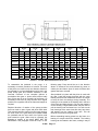
GARDNER DENVER®
TRIPLEX
SINGLE ACTING PUMP
MODELS
PZG
PZH
PZJ
PZK
PZL
PXL
–
–
–
–
–
–
7”
8”
9”
10”
11”
11”
OPERATING AND
SERVICE MANUAL
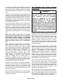
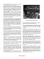
MAINTAIN PUMP RELIABILITY AND PERFORMANCE WITH
GENUINE GARDNER DENVER
PARTS AND SUPPORT SERVICES
Gardner DenverR and OPIR genuine pump parts are manufactured to design tolerances and developed for
optimum dependability. Design and material innovations are the result of years of experience with hundreds of
different pump applications. Reliability in materials and quality assurance are incorporated in our genuine
replacement parts.
Your authorized Gardner Denver and OPI distributor offers all the backup you’ll need. A worldwide network
of authorized distributors provides the finest product support in the pump industry.
Your local authorized distributor maintains a large inventory of genuine parts and he is backed up for emergency
parts by direct access to the Gardner Denver Master Distribution Center (MDC) in Memphis, Tennessee.
Your authorized distributor can support your Gardner Denver and OPI pump needs with these services:
1.
Trained parts specialists to assist you in selecting the correct replacement parts.
2.
Repair and maintenance kits designed with the necessary parts to simplify servicing your pump.
Authorized distributor service technicians are factory-trained and skilled in pump maintenance and repair. They
are ready to respond and assist you by providing fast, expert maintenance and repair services.
For the location of your local authorized Gardner Denver and OPI distributor refer to the yellow pages of
your phone directory or contact:
Distribution Center:
Gardner Denver
Master Distribution Center
5585 East Shelby Drive
Memphis, TN 38141
Phone: (901) 542-6100
Fax:
(901) 542-6159
Factory:
Gardner Denver
1800 Gardner Expressway
Quincy, IL 62301
Phone:
(217) 222-5400
Fax:
(217) 224-7814
INSTRUCTIONS FOR ORDERING REPAIR PARTS
When ordering parts, specify Pump MODEL and SERIAL NUMBER (see nameplate on unit). The Serial Number
is also stamped on top of the cylinder end of the frame (cradle area).
All orders for Parts should be placed with the nearest authorized distributor.
Where NOT specified, quantity of parts required per pump or unit is one (1); where more than one is required per
unit, quantity is indicated in parenthesis. SPECIFY EXACTLY THE NUMBER OF PARTS REQUIRED.
DO NOT ORDER BY SETS OR GROUPS.
To determine the Right Hand and Left Hand side of a pump, stand at the power end and look toward the fluid
end. Right Hand and Left Hand are indicated in parenthesis following the part name, i.e. (RH) & (LH), when
appropriate.
15-600
Page i
FOREWORD
Gardner DenverR and OPIR pumps are the result of advanced engineering and skilled manufacturing. To be
assured of receiving maximum service from this machine the owner must exercise care in its operation and
maintenance. This book is written to give the operator and maintenance department essential information for dayto-day operation, maintenance and adjustment. Careful adherence to these instructions will result in economical
operation and minimum downtime.
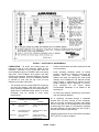
DANGER
Danger is used to indicate the presence of a hazard which will cause severe
personal injury, death, or substantial property damage if the warning is ignored.
WARNING
Warning is used to indicate the presence of a hazard which can cause severe
personal injury, death, or substantial property damage if the warning is ignored.
CAUTION
Caution is used to indicate the presence of a hazard which will or can cause
minor personal injury or property damage if the warning is ignored.
NOTICE
Notice is used to notify people of installation, operation or maintenance
information which is important but not hazard – related.
15-600
Page ii
TABLE OF CONTENTS
Maintain Pump Reliability and Performance ..........................................................................................................i
Instructions For Ordering Repair Parts...................................................................................................................i
Foreword................................................................................................................................................................ii
Index .....................................................................................................................................................................iv
SECTION 1, Danger Notices................................................................................................................................ 1
SECTION 2, Installation & Operating Instructions................................................................................................ 7
SECTION 3, Routine Maintenance & Service Instructions................................................................................. 16
SECTION 4, Dimensions & Running Clearances............................................................................................... 28
LIST OF ILLUSTRATIONS
Figure 1
Final Shimming ............................................................................................................................. 8
Figure 2
Crankcase Oil Requirements......................................................................................................... 9
Figure 3
Lubrication Schedule ..................................................................................................................... 9
Figure 4
Oil Capacities
Figure 5
Oil Filter Mounting ....................................................................................................................... 10
Figure 6
Sizes and Ratings - Models PZG and PZH ................................................................................. 12
Figure 7
Sizes and Ratings - Models PZJ and PZK .................................................................................. 13
Figure 8
Sizes and Ratings - Models PZL ................................................................................................. 14
Figure 9
Sizes and Ratings - Models PZL (High Pressure Fluid Cylinder)................................................ 14
Figure 10
Sizes and Ratings - Model PXL................................................................................................... 15
Figure 11
Jackshaft Bearing Installation...................................................................................................... 16
Figure 12
Jackshaft Removal/Installation Fixture........................................................................................ 16
Figure 13
Oil Seal Wear Sleeve Installation Tool ........................................................................................ 17
Figure 14
Connecting Rod Support ............................................................................................................. 18
Figure 15
Eccentric and Gear Assembly Support ....................................................................................... 19
Figure 16
Main Bearing Cartridge Lifting & Locating Devices ..................................................................... 19
Figure 17
Table of Metric Equivalents for Dimensions (Inches) .................................................................. 20
Figure 26
Installation of Push Rods............................................................................................................. 25
........................................................................................................................... 10
15-600
Page iii
INDEX
Maintain Pump Reliability And Performance ...............i
Maintenance Schedule.............................................11
Ordering Repair Parts..................................................i
SECTION 3...............................................................16
Foreword.....................................................................ii
Jackshaft ..................................................................16
SECTION 1................................................................ 1
Lube Oil Pump..........................................................18
Hammer Lug Fasteners............................................. 1
Connecting Rods ......................................................18
Valve Seat Pulling...................................................... 2
Eccentric And Gear AssemblyError! Bookmark not
Hydraulic Puller.......................................................... 2
defined.
Wedge Puller ............................................................. 2
Eccentric Cam Bearings...........................................20
Covers And Guards ................................................... 2
Assembly Of Eccentric And Gear Assembly In Frame
Equipment Moving And Lifting................................... 2
..................................................................................21
Pressurized Pump Systems ...................................... 3
Main Bearings...........................................................21
Flammable, Hot, Cold Or Corrosive Fluidpumping.... 4
Crosshead Pins ........................................................24
High Pressure Liquid Jetting, Blasting And Cleaning 5
Push Rods ................................................................24
SECTION 2................................................................ 7
Crossheads ..............................................................25
Start-Up ..................................................................... 7
Crosshead Slides .....................................................25
Location ..................................................................... 7
Oil Stop Heads .........................................................25
Suction Line ............................................................... 8
Valve Chambers .......................................................25
Relief Valves.............................................................. 8
Liner Clamp And Liners............................................26
Surge Chamber ......................................................... 8
Pistons......................................................................26
Starting A New Pump ................................................ 8
Piston Rod ................................................................26
Lubrication ................................................................. 9
Piston Washing System ...........................................26
Oil Filter ................................................................... 10
Maintenance Of Valves ............................................26
Heat Exchanger ....................................................... 10
Suction Strainer ........................................................27
Direction Of Rotation ............................................... 10
SECTION 4...............................................................28
Crosshead Drains .................................................... 11
Operation ................................................................. 11
15-600
Page iv
SECTION 1
DANGER NOTICES
operators and maintenance personnel to refresh their
memories in safe procedures and practices.
DANGER
Read and understand the following DANGER
NOTICES before moving or operating the pump or any
pump package unit equipment.
Reciprocating pumps are machines capable of
producing high fluid pressures and flow rates and are
designed to be used with proper care and caution by
trained, experienced operators.
TO AVOID
PERSONAL INJURY, DEATH AND/OR EQUIPMENT
DAMAGE,
READ
AND
THOROUGHLY
UNDERSTAND
THE
FOLLOWING
DANGER
NOTICES PLUS THE ENTIRE OPERATING AND
SERVICE MANUAL BEFORE ATTEMPTING TO
MOVE OR OPERATE THE PUMP. Contact a Gardner
Denver service representative if you are unable to
comply with any of the danger notices or procedures
described in these documents.
Closely examine the data plate upon pump delivery to
become thoroughly familiar with the operating limits for
this pump model.
The pump must never be
operated at speeds, pressures or horsepower
exceeding the maximum values shown on the data
plate or at speeds below the minimum shown.
Failure to observe the operating limits shown on
the data plate could result in personal injury,
death, and/or equipment damage and will void the
warranty. Alterations to the pump, or application of
the pump outside the data plate limits, must not be
made without Gardner Denver written approval
together with a new data plate, as dangerous operating
conditions could result.
THE DANGER NOTICE AND DATA PLATES
PROVIDED ON THE EQUIPMENT MUST NOT BE
REMOVED,
PAINTED
OVER,
HIDDEN
OR•
DEFACED. They must be replaced if they become
damaged or unreadable. Provisions should be made
to have the following written danger notices plus the
pump operating and service manual readily available to
operators and maintenance personnel. In addition,
copies of all pump system accessory component (e.g.
pressure relief valve, pulsation dampener, suction
stabilizer, engine, electric motor, etc.) operating and
service manuals should be readily available for
operator and maintenance personnel use. Read and
follow all the precautions and instructions contained in
these manuals. If any of these documents are lost or
become illegible they must be replaced immediately.
The danger notices plus the operating and service
manuals should be reread periodically by both
15-600
Keep in mind that full operator attention and alertness
are required when operating high pressure pumping
equipment. Operators should not begin or continue
operations when tired, distracted or under the influence
of alcohol or any type of prescription or nonprescription
drugs.
The timely replacement of expendable parts and any
other worn or damaged parts can prevent equipment
damage and possible injury. The original parts used in
Gardner Denver pumps are designed and tested to
exacting standards to provide high quality performance
and durability. Your best insurance in maintaining
these characteristics is to use genuine Gardner Denver
replacement parts.
A broad range of danger notices are covered on these
pages, however, they cannot substitute for training,
experience and common sense in the safe operation of
high pressure pumping equipment.
HAMMER LUG FASTENERS
DANGER
On pumps or pump package units equipped with
hammer lug connectors and/or hammer lug valve
covers the following precautions must be observed to
avoid personal injury, death and/or equipment damage
due to contact with the hammer, hammer bar, broken
parts from the hammer, hammer bar or lugs or other
objects propelled by hammer blows. When tightening
or loosening hammer lug connectors and valve covers,
operators or maintenance personnel should:
Inspect the hammer, hammer lugs and hammer bar, if
one is used, to insure they are all in good condition.
Replace any of these parts which are cracked,
damaged or badly worn.
Wear safety shoes and goggles.
Alert other personnel to move away from the area.
Check to insure they have safe footing.
Fully engage the hammer bar, if one is used, to
prevent it from disengaging violently from the cover
as a blow is struck.
Wipe their hands and the hammer handle and
maintain a firm grip on the handle to avoid losing
control of the hammer while swinging and striking.
Page 1
•
•
Carefully swing the hammer to avoid striking
themselves, another person and objects other
than the targeted lugs or hammer bar.
Avoid swinging the hammer above shoulder
height.
VALVE SEAT PULLING
DANGER
The following precautions must be observed by
operators and maintenance personnel to avoid
personal injury, death and/or equipment damage from
contact with the puller, hammer, wedge or broken
parts from these components when using either a
hydraulic or wedge valve seat puller:
Hydraulic Puller
•
•
•
Wear safety shoes and goggles.
Chain or tie the jack down as it will jump violently
when the valve seat disengages from the valve
deck.
Check to insure the pressure applied by the
hydraulic pump does not exceed the hydraulic
ram maximum pressure rating.
Wedge Puller
•
•
Grind off any mushroomed material from the
wedge before use.
Follow the DANGER notices listed above in the
hammer lug section, but substitute the term
wedge for hammer lub an hammer bar.
COVERS AND GUARDS
DANGER
All pump covers must be securely
fastened in proper position at all times
when the pump is operating to avoid
personal injury or death from moving
parts. In addition, all moving parts on
the entire pump package, including but
not limited to, the engine or motors,
drive shafts, belts, chains, pulleys,
gears, etc., must be equipped with
guards or covers, which must also be
securely fastened in proper position at
all times when the equipment is
operating.
Covers and guards are intended to not only protect
against personal injury or death, but to also protect
the equipment from damage from foreign objects.
15-600
EQUIPMENT MOVING AND LIFTING
DANGER
Heavy equipment including pumps, pump package
units and components should only be moved or lifted
by trained, experienced operators, who are physically
and mentally prepared to devote full attention and
alertness to the moving and lifting operations. An
operator should be fully aware of the use, capabilities,
and condition of both the equipment being moved and
the equipment being used to move it.
DANGER
Failure to follow safe and proper pump,
pump package or component lifting or
moving procedures can lead to
personal
injury,
death
and/or
equipment damage from shifting,
falling or other unexpected or
uncontrolled equipment movements.
Make sure the hoist, lift truck, ropes, slings, spreader,
or other lifting equipment you are using is in good
condition and has a rated lifting capacity equal to or
greater than the weight being lifted. Lifting devices
must be checked frequently for condition and
continued conformance to rated load capacity. They
should then be tagged with the inspected capacity
together with the date of inspection.
Fully assembled pumps and pump package units are
heavy and should only be moved using the specified
lifting lugs or attachments.
Many individual components have lifting eyes or
lugs which must not be used to lift assemblies, as
they are designed to bear the weight of the
component only.
Before lifting the individual component check to insure
the lifting attachment is firmly secured to the
component with undamaged, properly torqued
fasteners, sound welds, or other secure attachments.
Examine the lifting eyes, lugs, slots, holes or other
projections to insure they are not cracked, otherwise
damaged or badly worn. The repair of existing or
addition of new welded lifting eyes, lugs or other
projections should only be performed by experienced,
qualified welders.
Package units should be lifted with spreaders
connected to the lifting attachments normally built into
the package unit support skid. Packages too large to
lift fully assembled should be separated into smaller
Page 2
The relief valve should be placed in the flowing
discharge line and not at the opposite end of the
discharge manifold in a dead end connection. The
dead end may become clogged with solid material
carried in the fluid, which could prevent proper relief
valve operation.
loads. For these smaller loads the lifting devices
should be fastened to the lifting attachments normally
built into the individual motor, engine, pump or
transmission/torque converter, or their separate
support skids.
When lifting subassembled components, for example
a suction stabilizer attached to suction piping or a
discharge pulsation dampener attached to a strainer
cross and piping, use special lifting slings designed to
safely support the combined weight of the
components. If a crane or hoist is being used to lift
large components or assemblies, one or more
persons should assist the operator from the ground
with guide lines attached to the equipment being
moved to properly position it and prevent uncontrolled
movement.
DANGER
Never place a shut-off valve or any
other component between the pump
discharge connection and the pressure
relief valve.
Make sure the pressure relief valve is installed so any
pressurized relief discharge from the valve is directed
away from possible contact with people or equipment.
The relief valve must be set to relieve at a pressure
equal to or below the maximum pressure values
shown on the pump data plate. However, if a
component is used in the discharge system with a
lower rated pressure capability than that listed on the
pump data plate, the pressure relief valve must be set
to relief valve must be set to relieve at a pressure
equal to or below the rated capability of the lowest
rated component.
When you start to lift a pump, package unit,
subassemblies or individual components and you
observe the equipment is tilting, or appears
unbalanced, lower the equipment and adjust the lifting
device to eliminate these improper lifting conditions
before proceeding to move the equipment.
It is poor practice and dangerous to allow the
equipment to pass over or close to your body or
limbs. Be prepared to move quickly out of danger if
equipment starts to fall, slip or move unexpectedly
toward you.
PRESSURIZED PUMP SYSTEMS
•
DANGER
Fluids under high pressure can
possess sufficient energy to cause
personal
injury,
death
and/or
equipment damage either through
direct contact with escaping fluid
streams or by contact with loose
objects the pressurized fluid propels.
Operating a pump against a blocked or restricted
discharge line can produce excessive pressures in
the entire discharge system, which can damage or
burst discharge system components.
DANGER
Never operate a pump without a
properly sized pressure relief valve
located in the flowing discharge line
immediately adjacent to the pump
discharge connection.
15-600
•
•
Before starting the pump every time, check to
insure:
The pressure relief valve is in good operating
condition and has been set to the proper relief
pressure.
Any pipe line used to direct pressurized relief flow to
another location, such as a collecting tank, is not
blocked.
The discharge system is not blocked and all the
discharge line valves are open.
Check all fluid end discharge system components
including pipe, connections, elbows, threads,
fasteners, hoses, etc., at least once every six
months to confirm their structural adequacy. With
time, wear, corrosion and fatigue can reduce the
strength of all components. Magnetic iron and steel
components should be checked with magnetic particle
or dye penetrate crack detection equipment.
Nonmagnetic materials should be checked for cracks
with dye penetrants. All metallic components should
also be visually checked during these inspections for
signs of corrosion. If a component shows evidence of
cracking or loss of material due to corrosion it must be
replaced with a new part.
Continually monitor suction and discharge hose
assemblies when the pump is operating for leakage,
kinking, abrasion, corrosion or any other signs of wear
or damage.
Page 3
Worn or damaged hose assemblies should be
replaced immediately. At least every six months
examine hose assemblies internally for cut or bulged
tube, obstructions and cleanliness. For segment style
fittings, be sure that the hose butts up against the
nipple shoulder, the band and retaining ring are
properly set and tight and the segments are properly
spaced. Check for proper gap between nut and
socket or hex and socket. Nuts should swivel freely.
Check the layline of the hose to be sure that the
assembly is not twisted. Cap the ends of the hose
with plastic covers to keep them clean until they are
tested or reinstalled on the pump unit. Following this
visual examination, the hose assembly should be
hydrostatically tested, on test stands having adequate
guards to protect the operator, per the hose
manufacturer’s proof test procedure.
Fluid end component inspections should be
performed more frequently than every six months
if pressures above 2,500 PSI are used in the
discharge system or if corrosive, flammable or
hot (over 110º F) fluids are being pumped.
Proper stuffing box packing selection is important for
safe pump operation. Contact a Gardner Denver
service representative for assistance in selecting the
proper packing before beginning operation.
Before starting the pump the first time and periodically
thereafter check the pump, suction and discharge
system fastener torques versus the values listed on
page 12 to insure proper tightness. Over and under
torquing can damage threaded pipes, connections
and fasteners, which may lead to component damage
and/or failure. Replace all components found to be
damaged or defective. On pumps equipped with
stuffing boxes, the gland must be engaged by at least
three (3) threads to hold the discharge pressure of the
pump.
Block the crankshaft from turning and make certain
that all pump drive motor or engine start switches or
starter controls are clearly tagged with warnings not to
start the pump while repair work is in process.
DANGER
Do not attempt to service, repair, or
adjust the plunger packing or otherwise
work on the pump while the unit is
operating. Shut off the pump drive
motor or engine and relieve the fluid
pressure in the pump suction and
discharge systems before any work or
investigation is performed on the pump
or pump systems.
15-600
Whenever the pump is operating, continually monitor
the entire suction, discharge and pump lubricating
systems for leaks. Thoroughly investigate the cause
for leakage and do not operate the pump until the
cause of the leak has been corrected. Replace any
parts which are found to be damaged or defective.
When a gasketed joint is disassembled for any
reason, discard the used gasket and replace it with a
new, genuine Gardner Denver gasket before
reassembling the joint.
Due to the high working pressures contained by the
fluid cylinder, discharge manifold and discharge
piping, welding on these components is not
recommended. If welding on the discharge system
cannot be avoided, only experienced, qualified
welders should be used. In addition, the welded part
should be hydrostatically proof tested in the shop with
water or hydraulic fluid to one and one half times
maximum discharge system working pressure, with
no observable fluid leakage, before the part is
reinstalled in the pump system.
In summary, high pressure fluid streams can possess
sufficient energy to cause personal injury, death
and/or equipment damage. These results can occur
either through direct contact with the fluid stream or
by contact with loose objects the fluid stream has
propelled, if the pump system is improperly used, or if
the fluid is misdirected, or allowed to escape from
defective or improperly maintained equipment.
FLAMMABLE, HOT, COLD OR CORROSIVE FLUID
PUMPING
DANGER
Extreme caution must be exercised by
trained and experienced operators
when flammable, hot, cold or corrosive
fluids are being pumped in order to
avoid personal injury, death and/or
equipment damage due to explosion,
fire, burn, extreme cold or chemical
attack.
Never operate a pump which is pumping
hydrocarbons or other flammable, hot, cold, or
corrosive fluids when any part of the pump, suction
system or discharge system is leaking. Stop the
pump immediately if any leakage, other than a few
drops per minute of packing weepage, is observed.
Keep all flame, sparks, or hot objects away from any
part of the pump, suction system, or discharge
system.
Shield the pump, suction system and
discharge system to prevent any flammable, hot, cold
Page 4
or corrosive fluid leakage from dripping or spraying on
any components, flame, sparks, hot objects or people.
Inspect the plungers, packing, gaskets and seals for
fluid leakage frequently and replace all worn or leaking
parts.
Selection of the proper gaskets, seals and stuffing box
packing is even more critical when flammable, hot, cold
or corrosive fluids are being pumped than when other,
inherently less dangerous fluids are used. Contact a
Gardner Denver service representative for assistance
in selecting the proper gaskets, seals and packing
before beginning operation.
Since some packing weepage into the cradle area is
inevitable, the drain at the bottom of the cradle must be
connected to a drain line which conducts the fluid
leakage to a collection container located in a protected
area. The entire drain system and container must be
constructed of materials resistant to attack from the
pumped fluid or from explosion or fire of the pumped
fluid.
Heavy duty cradle covers must be securely
fastened in the proper position on the pump at all
times when the pump is operating. If the pumped
fluid releases harmful, explosive or flammable
vapors the covers must be vented to conduct the
fumes away from the pump unit to a nonhazardous
area.
Before beginning pumping operations or starting the
pump power source (whether an engine or electric
motor) check the atmosphere all around the pumping
site for the presence of flammable or explosive vapors.
Do not begin operation and stop ongoing operation if
flammable or explosive vapors are detected. Hot
surfaces, sparks, electric current or engine exhaust
could ignite flammable or explosive vapors. Each
engine used as a power source on pumping units
where flammable or explosive vapors could form
should be equipped with an air inlet shut-off. If
flammable or explosive vapors are present in the
pumping site atmosphere, an engine could continue to
run on these vapors even after the engine fuel line is
shut-off if an air inlet shut-off is not used.
In addition, on pumping units used where flammable or
explosive vapors could form, all electric motors used
as power sources must be of explosion proof
construction and all electrical components and wiring
must meet the current National Electrical Code for
explosive atmospheres.
These precautions must be taken to avoid possible
personal injury, death and/or equipment damage from
explosion, fire or burns.
15-600
HIGH PRESSURE LIQUID JETTING, BLASTING
AND CLEANING
DANGER
Extreme caution must be exercised if
any type of wand, gun, nozzle or any
other pressure and flow directing
device is attached to the pump
discharge system for use in jetting,
blasting, cleaning, etc. This type of
equipment must be used with utmost
care by trained, experienced operators.
High pressure fluid streams can either
by direct contact or by propelling loose
objects, cause serious personal injury
or death to the operators and/or other
persons.
Pressure or flow directing devices often receive
pressurized flow through flexible hoses, which can
burst if they are kinked, cut, abraded or are otherwise
worn, damaged or pressured above their rated
capacity. Protect the hose and connections from
damage by people, objects and vehicles. A broken,
cut or otherwise burst hose can release pressurized
fluid which may cause personal injury, death and/or
equipment damage.
High pressure fluid from hand held or hand directed
pressure and flow directing devices may overpower an
operator’s ability to control or direct the device, which
could lead to personal injury, death and/or equipment
damage.
The operator must brace against the
backward thrust of a hand held device. In addition, a
safety harness or safety net must be used when
working in an area where the operator could be injured
in a fall. Stand to the side of any tubing or container
being sprayed to avoid back spray and never operate a
hand held device above shoulder level.
Never direct the pressurized fluid stream at yourself or
any other person, control valves, the pump, pump
drive, suction or discharge systems. The pressurized
stream can cause serious personal injury or death and
can also change valve or control settings which could
dangerously increase the delivery pressure to the
pressure and flow directing device.
When operating a pressure and flow directing device,
use only equipment which automatically shuts off flow
when an operator releases hand or foot pressure on
the pressurized flow trigger control to prevent injury if
the operator is overpowered or becomes disabled.
Page 5
Check to insure this automatic shut-off equipment is
operating properly before every use and never
circumvent the automatic shut-off for any reason or by
any means when operating the equipment.
The equipment must be shut down and the system
pressure released before changing or disconnecting
wands, nozzles, guns, hoses, connections or any
other pressurized system components.
When operating any type of high pressure liquid
jetting, blasting or cleaning devices the operators
must always wear protective clothing including, but
not limited to, a hard hat with full face visor, heavy
duty rain coat and pants, boots with nonskid sole and
safety toe, rubber gloves with rough grip surface and
ear noise protection.
All pressure containing devices including wands,
nozzles, guns, connections, etc., plus all automatic
shut-off, pressure and control equipment should be
treated with care. Protect them from damage by
people, objects and vehicles. Never lay them in dirt,
mud, ice or other loose material which could plug the
fluid opening or interfere with their operation. Never
use the wand, nozzle, gun, etc. to pry loose material
off items being cleaned.
Full operator attention and alertness are required
when operating this equipment to avoid personal
injury, death and/or equipment damage.
The
operators should take frequent rest breaks and cease
operations when they become tired or distracted.
Before the equipment is started, the work area must
be inspected and properly prepared to avoid personal
injury, death and/or damage to equipment. Make
sure the work area is checked for hazardous fumes,
has adequate ventilation for engine exhaust and
sufficient drainage for released fluid. Check the work
area for electrical equipment, connections, outlets,
fixtures, or lines. If any are present they must be
made water tight and the electrical power to these
devices must be shut off to avoid electrical shocks
from fluid contact. The work area should be clearly
marked and roped off to keep unauthorized people
and vehicles from entering. Remove all loose parts,
tools and equipment from the work area before
beginning operation.
All pressure containing devices including wands,
nozzles, guns, hoses, connections, etc., should be
regularly checked for condition. These components
should all be tagged with their tested pressure
capabilities together with the date testing was
performed. Always be aware of the pressure level
in the system and never connect any equipment
to the system which has a rated or tested
pressure capability below the system operating
pressure.
15-600
Before starting operation in a cold environment, check
to make sure there is no ice in the fluid system and
repeat this inspection each time before operation is
restarted.
Before
purchasing
wands,
nozzles,
guns,
connections, and hose, etc., manufacturers of these
components should be contacted for detailed
information on the design and safety features
incorporated in their products. After careful study of
various manufacturers products, we recommend that
only those wands, nozzles, guns, connections and
hose, etc., be considered for purchase that you judge
to offer the highest quality of design, construction and
safety, since these components are among the most
critical to the safe operation of high pressure liquid
jetting, blasting and cleaning equipment.
After you have selected and purchased these
components, follow the manufacturer’s instructions
completely in their use.
In summary, high pressure jetting, blasting and
cleaning are inherently dangerous, as the
pressures and flow rates needed to remove scale,
clean, etc. are sufficient to cause personal injury,
death and/or equipment damage resulting from,
but not limited to, any of the conditions described
in the above Danger Notices.
Page 6
SECTION 2
INSTALLATION & OPERATING INSTRUCTIONS
FOR GARDNER DENVER PZ SERIES & PXL SINGLE ACTING POWER PUMPS
Reference to Parts List covering the Model Pump being serviced is recommended in connection with this
Instruction Manual.
Repair Parts Lists with Sectional Views are available from any Gardner Denver Sales and Service
Office. When ordering parts, always give size and serial number of pump. Always use genuine Gardner
Denver parts. For efficient, factory-trained service, consult a Gardner Denver Service Specialist.
START-UP – Pumps are shipped from the factory
without oil in the crankcase. The hood should be
removed and the power end examined and cleaned if
necessary. The pump may have been in storage or in
the yard for sometime and as a consequence dirt may
have entered the crankcase. Parts may have been
robbed from the pump during storage and not
replaced. All nuts and screws should be tightened.
Be sure all valves in the discharge line are open. No
valve should be installed between the pump and
pressure relief valve in discharge line.
To prevent excessive wear on the fluid pistons and
packing when starting, remove a suction valve cover
plate on each side of the fluid end and prime the pump.
Pump should be started slowly, if possible, and should
be operated for several hours with practically no
discharge pressure. Check oil level as it may be
necessary to add a small quantity of oil to compensate
for that adhering to the walls of the crankcase the
moving parts. The pump may then gradually be
brought up to full speed and full working pressure.
Watch for undue heating or abnormal noise in the
working parts. Check all joints in the suction line to be
sure there are no air leaks.
DANGER
When working on any pump, be certain
there is no fluid pressure on either the
suction or discharge side. Pressure on
the fluid end might move the pump and
cause damage or injury to personnel. It
is recommended that all suction valve
covers be removed to avoid fluid
pressure building up against the pistons
or plungers.
15-600
DANGER
If the drive is not to be removed, it is
recommended that the air line to the
clutch be disconnected to prevent
accidental starting of the pump.
LOCATION - Pump should be set level and solidly
supported. The drive should be accurately aligned.
Pump should be placed as close to the slush pit as
possible to keep the suction line short and direct.
Locate pump as low as possible to maintain a
minimum suction lift to the centrifugal charging pump
which is used because of the high speed of this type of
mud pump.
When the pump skid or master skid is to be bolted or
welded to a platform or deck in the field, it is necessary
that the following “Final Shimming Procedure” be
followed.
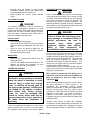
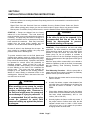
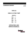
Final Shimming Procedure - After the pump skid or
master skid has been bolted or welded to a stationary
platform or deck, proceed as follows:
a.
Remove the cap screws used to secure the pump
frame to its skid.
b.
At each foot where a space exists between foot
and skid, place a dial indicator on the frame foot
and skid as shown in FIGURE 1. Set dial to
ZERO.
c.
Place shims between frame foot and skid where
space exists so the dial indicator shows the frame
has been raised approximately .005 to .010
inches (.126 to .254 mm).
d.
Securely tighten the frame to skid cap screws. If
the proper number of shims were used, the dial
indicator should return to within +/-.003 inches
(.076 mm) of zero. If not, repeat the procedure
changing number of shims used.
Page 7
DANGER
Never install a shutoff valve in the line
between the pressure relief valve and
the pump discharge manifold.
NOTE:
This is only when the skid is secured
to a STATIONARY foundation.
DIAL
INDICATOR
FRAME SUPPORT
FOOT
SHIM
A75738
FIGURE 1 – FINAL SHIMMING
SUCTION LINE - Suction pipe or hose to centrifugal
charging pump should be a minimum of 12 inches
(304.8 mm) diameter and as short as possible. Always
use eccentric reducers when reducing suction pipe
size. Suction line should slope up toward the charging
pump at uniform grade to prevent air pockets being
formed. Suction line must be absolutely tight as any air
leaking into the line will reduce the capacity of the
pump and cause a hydraulic hammer or knock. If it is
necessary to have bends in the suction line they
should have long radius sweeps and be kept to a
minimum in quantity. 10 PSI - 40 PSI suction required.
Suction line should be supported near centrifugal
charging pump to keep strain from breaking the casing
at suction flange.
At least one section of hose in the suction line is
desirable to isolate pulsations or vibration. Total
suction line should be as short as installation
conditions permit. THIS IS IMPORTANT.
A suction strainer is recommended for the suction line
of every pump. It must be checked frequently and
cleaned whenever necessary. A commercial strainer
may be installed in suction line ahead of the pump.
It is recommended that a 50 PSI (3.515 kg/cm2) gauge
with a needle valve for protection be installed in the
suction line at the discharge of the centrifugal charging
pump. This gauge will indicate if pump is charging or if
suction valves are not working properly.
RELIEF VALVES - The pump should be protected
from excess discharge pressure by a 3 inch (76.2 mm)
relief valve. This valve should be installed in a vertical
position in a tee mounted directly onto either end of
discharge manifold or discharge cross.
15-600
If more than one pump is used, a pressure release
valve should be furnished for each pump. A handoperated pressure release valve should be installed in
discharge line following the relief valve, with discharge
line leading to mud tank. This valve is used to bleed air
from discharge line in starting. It is also used to relieve
pressure in starting more than one pump in parallel.
SURGE CHAMBER - A surge chamber is essential.
One MUST be used for protection to surface
equipment and to reduce pulsations when pumping
gaseous mud. A nitrogen-charged pressure-bag type
surge chamber is recommended. The surge chamber
must be kept properly charged, as instructed by the
manufacturer.
STARTING A NEW PUMP - It is recommended that
the drive be arranged to turn the pump in the direction
indicated by arrow shown on the sectional view in this
book, on outline prints, and indicated on pump frame.
This book provides for crosshead load to be carried on
the lower side. This means better lubrication and quiet
operation. Lube oil pumps are not automatice
reversing.
If the PZ series or the PXL pumps are to be run in
reverse direction, refer to “Lube Oil Pump”.
Pumps are shipped from the factory without oil in the
crankcase. The hood should be removed and the
power end examined and cleaned if necessary. The
pump may have been in storage or in the yard for
some time, and as a consequence, dirt may have
entered the crankcase. Drain all water accumulated in
the bottom of the crankcase. Fill crankcase with oil of
proper grade to the proper level. Quantity shown on
lubrication data plate indicates the approximate oil
requirements. All nuts and cap screws should be
checked for tightness.
It is recommended that the fluid end of the pump be
primed to prevent excessive wear on the fluid pistons
and liners when starting. PRIMING IS IMPORTANT!
IT LUBRICATES THE PISTONS IN THE LINERS.
Pump should be started slowly but not run below half
of rated speed. Recheck oil level as it may be
necessary to add a small quantity of oil to crankcase
and the moving parts. The pump may then be
gradually brought up to full speed and full working
pressure. Check all joints in the suction line to be sure
there are no air leaks.
Page 8
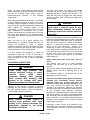
FIGURE 2 – CRANKCASE OIL REQUIREMENTS
LUBRICATION - All power end working parts are
lubricated by the oil in the crankcase. Check oil level
frequently. Selection of oil is to be taken from the
recommendations given in FIGURE 2 and on the pump
data plate. Local conditions and practice may also
influence the selection. Essential additives are foam
and oxidation inhibitors. Oil is to be added as required
to maintain oil level near the top of the oil level
indicator on the side of the frame.
•
Oil viscosity must not exceed 7000 SSU at start-up
and must be between 1500 SSU and 200 SSU
while operating, regardless of the oil temperature or
grade used. A crankcase heater and/or an oil heat
exchanger may be needed to meet these
requirements.
LUBRICATION SCHEDULE
Frequency
Type
Procedure
Daily
*A.P.I. Type GL-5
Lubricant
Check oil level with pump
running.
Daily
50% Water Plus 50%
Water Soluble Oil
Check fluid level in piston
wash tank.
1000 Hours
*A.P.I. Type GL-5
Lubricant
Change oil and clean
inside of frame. Change
oil filter element.
FIGURE 3 – LUBRICATION SCHEDULE
15-600
•
Failure to follow these lubrication requirements will
void the warranty.
•
Some operating conditions and/or oil brands
produce excessive oil foaming, even when the
specified GL-5 oils containing antifoaming
additives are used. Oil foaming can cause pump
damage, as oil bubbles will not lubricate moving
parts properly. If significant oil foaming occurs,
contact Gardner Denver Marketing or Service,
(217) 222-5400, for the current factory
recommended defoamant to be added to the
lubricating oil.
•
Oil must have antiwear, antifoaming, noncorrosive
and rust inhibiting additives.
Oil is constantly circulated through a renewable
element filter and then through a heat exchanger,
when one is used, by means of a rotary pump driven
from the main gear. Oil is discharged into an elevated
oil feed trough, from which it is conducted to jackshaft
and main bearings. Oil also flows from the trough to
lubricate the connecting rod bearings.
Operating temperatures of the oil should be kept below
200oF (93.3oC) to reduce oxidation.
Page 9
On units equipped with a heat exchanger, oil flows
through the oil filter before going through the heat
exchanger.
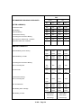
OIL CAPACITIES
Pumps Without Heat Exchanger
Model
PZG
PZH
PZJ
PZK
PZL
PXL
Cast Frame
60 Gal. (227.1 Liters)
60 Gal. (227.1 Liters)
70 Gal. (264.9 Liters)
85 Gal. (321.8 Liters)
85 Gal. (321.8 Liters)
85 Gal. (321.8 Liters)
Fabricated Frame
None
85 Gal. (321.8 Liters)
105 Gal. (397.4 Liters)
100 Gal. (378.5 Liters)
100 Gal. (378.5 Liters)
None
Pumps With Heat Exchanger
Model
PZG
PZH
PZJ
PZK
PZL
PXL
Cast Frame
41 Gal. (155.2 Liters)
41 Gal. (155.2 Liters)
50 Gal. (189.3 Liters)
85 Gal. (321.8 Liters)
85 Gal. (321.8 Liters)
85 Gal. (321.8 Liters)
Fabricated Frame
None
65 Gal. (321.8 Liters)
85 Gal. (397.4 Liters)
None
None
None
Time between oil changes depends upon local and/or
operating conditions. Under normal circumstances, if
the crankcase is kept clean, it should not be necessary
to change the oil more than once in 1000 hours of
operation. Many operators change oil after each well
drilled. Oil should be changed if found to be dirty or
contaminated with mud or water, as the oil lubricated
roller bearings will be damaged by contamination. An
oil change is comparatively inexpensive, as the
approximate crankcase capacities are shown above.
In order to assure proper lubrication, the PZG, PZH &
PZJ pumps should not be run under 10 RPM for more
than a few minutes at a time without providing
additional lubrication from an extra external oil pump.
The PZK, PZL & PXL pumps should not be run under
40 RPM.
The oils normally used in large mud pumps are quite
viscous at lower temperatures. When starting cold, the
pump should be started slowly and brought up to
operating speed slowly. This practice will assure
proper lubrication of all working parts before pump is
fully loaded.
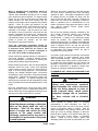
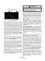
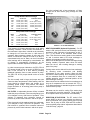
OIL FILTER - A replaceable element oil filter is located
inside the pump crankcase. Filter mounting flange is on
oil is changed or every 1000 hours of operation. Filter
element is protected from excessive internal oil
pressure by a relief valve between it and the oil pump.
Filter element should be replaced each time crankcase
oil is changed or every 1,000 hours of operation. The
filter element is protected from excessive internal oil
pressure by a relief valve between it and the oil pump.
15-600
FIGURE 5 – OIL FILTER MOUNTING
HEAT EXCHANGER (Optional Equipment) - For PZ
series & PXL pumps a bronze heat exchanger can be
provided to keep crankcase oil temperature at 160° F
(71.1° C) by means of an automatic water control
valve. This valve has a sensing probe in the crankcase
oil, and it monitors water to the heat exchanger to
maintain oil temperature within close limits.
Water must be drained from the heat exchanger during
freezing weather. Ruptured water tubes will admit
water into the oil, with resulting damage to working
parts of the pump.
Cooling water can be drained from the heat exchanger
by removing water connections and blowing
compressed air into upper opening. Water will then
flow from the lower opening. Air is necessary, as water
will not otherwise drain due to small size of tubes,
capillary attraction, and the horizontal position of the
heat exchanger mounting.
Water should not be admitted to the heat exchanger as
long as oil temperatures do not exceed 160° F(71.1°
C). A dial thermometer is standard equipment on all PZ
series and PXL pumps.
Salt water can be used for cooling. Zinc anode plugs
are provided for corrosion protection. These plugs are
to be replaced when they have been corroded away.
DIRECTION OF ROTATION - The PZ series & PXL
pumps MUST be driven in the direction as shown by
arrow on sectional view, outline drawing and on pump
frame. The oil pump on PZG, PZH and PZJ models is
a nonreversible pump without adjustments described in
“Lube Oil Pump”, page 24.
Page 10
Running the pump in the prescribed direction insures
proper lubrication and quiet operation as the load on
the crosshead will be carried on the lower side.
CROSSHEAD DRAINS - PZ series & PXL pumps are
equipped with two plugged drain openings below and
in front of the crossheads. These openings are to drain
any possible leakage from the oil stop head packings
which collects in a small reservoir built into the frame.
This area should be drained daily.
It is recommended that these openings be piped
together and a valve installed to simplify the daily
draining. Failure to drain this area could result in
drilling mud in the power end and possible premature
failure.
OPERATION - For normal drilling operation, the
pumps are to be run at the ratings listed on pages 12
thru 15. In no case should pressure exceed that shown
for each diameter piston - to do so would subject
working parts to operating loads in excess of those for
which they were designed, resulting in reduced life.
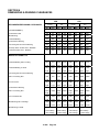
MAINTENANCE SCHEDULE FOR GARDNER DENVER “PZ” SERIES AND “PXL” PUMPS:
Daily:
Every Two Weeks:
1. Inspect condition of piston and liners. They should
be run until leakage of fluid is visible or becomes
excessive.
1. Remove valve cover locks. Clean threads on
locks and rings. Coat threads with moly coat
thread compound or heavy-duty lead base thread
compound. Replace if they are worn or cracked.
2. Clean inside frame cradle.
Monthly:
3. Clean and refill piston wash tank after excessive
contamination.
4. Check piston wash baffle, make certain nozzles
are not clogged.
1. Check all fluid cylinder studs and nuts for
tightness.
2. Remove and clean discharge cross strainer.
3. Check condition of oil stop head seals and
replace if worn or leaking excessively.
5. Check pulsation dampener for proper charge.
Weekly:
Every 1000 Hours:
1. Remove valve covers and gaskets. Replace if cut
or warn.
1. Clean frame oil drain magnet during oil change.
2. Check fluid valves and seats for wear. Replace
cut or worn inserts and valves.
2. Clean frame oil drain plug magnets located in
front of crossheads and clean the oil passage.
3. Inspect urethane bushing in suction
discharge valve guides and replace if worn.
3. Clean inside frame during regular oil change.
and
4. Inspect piston locknut. Replace if damaged,
corroded, or if nylon locking insert has lost its
effectiveness. Nut should be used only three
times and then replaced. Do not overtighten nuts.
15-600
Every 6 Months:
1. Replace oil stop head seals even though leakage
is not evident.
Page 11
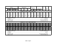
Cylinder
Qty.
3
3
3
3
3
3
Displacement
Diameter
Stroke
Inches
mm
Inches
mm
7
6 1/2
6
5 1/2
5
4 1/2
177.8
165.1
152.4
139.7
127.0
114.3
7
7
7
7
7
7
177.8
177.8
177.8
177.8
177.8
177.8
Gal. Per Liter Per Gal. Per Liter Per
Rev.
Rev.
Min.
Min.
3.5
3.02
2.57
2.16
1.79
1.45
Maximum
Pressure
PSI
kg/cm2
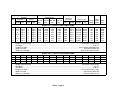
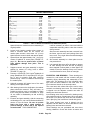
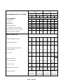
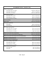
MODEL PZG – 550 H.P. TRIPLEX MUD PUMP
13.25
507
1919
1673
117.6
11.43
437
1654
1940
136.4
9.73
373
1412
2277
160.1
8.18
313
1185
2710
190.5
6.78
259
980
3279
230.5
5.49
210
795
4048
284.6
Piston Load
Pounds
kg
Pump
RPM
64,380
64,380
64,380
64,380
64,380
64,380
29,202
29,202
29,202
29,202
29,202
29,202
145
145
145
145
145
145
Jackshaft
RPM
Input
HP
670
670
670
670
670
670
550
550
550
550
550
550
Weight Complete Pump ............................................................................................................................. 17,410 lbs. (7897.04 kg)
Gear Ratio .......................................................................................................................................................................... 4.625 to 1
Length Over Skid ........................................................................................................................................ 120 Inches (3048.0 mm)
Width Over Skid ............................................................................................................................................. 50 Inches (1270.0 mm
3
3
3
3
3
3
3
3
7
6 1/2
6¼
6
5 1/2
5
4 1/2
4
177.8
165.1
158.8
152.4
139.7
127.0
114.3
101.6
8
8
8
8
8
8
8
8
203.2
203.2
203.2
203.2
203.2
203.2
203.2
203.2
4.0
3.45
3.19
2.94
2.47
2.04
1.65
1.31
MODEL PZH – 750 H.P. TRIPLEX MUD PUMP
15.14
580
2196
1996
140.3
13.06
500
1893
2315
162.8
12.08
462
1749
2504
176.0
11.13
426
1613
2717
191.0
9.35
358
1355
3233
227.3
7.72
296
1120
3912
275.1
6.25
240
908
4830
339.6
4.96
189
715
5000*
351.5*
76,817
76,817
76,817
76,817
76,817
76,817
76,817
62,832*
34,844
34,844
34,844
34,844
34,844
34,844
34,844
28,510*
145
145
145
145
145
145
145
145
652
652
652
652
652
652
652
652
Weight Complete Pump ............................................................................................................................. 21,650 lbs. (9820.27 kg)
Gear Ratio .............................................................................................................................................................................. 4.5 to 1
Gear Ratio .............................................................................................................................................................................. 4.5 to 1
Length Over Skid ................................................................................................................................... 193.62 Inches (4917.9 mm)
Width Over Skid ............................................................................................................................................. 89 Inches (2260.6 mm
15-600
Page 12
750
750
750
750
750
750
750
613*
Cylinder
Qty.
3
3
3
3
3
3
3
3
Displacement
Diameter
Stroke
Inches
mm
Inches
mm
7
6 1/2
6¼
6
5 1/2
5
4 1/2
4
177.8
165.1
158.8
152.4
139.7
127.0
114.3
101.6
9
9
9
9
9
9
9
9
228.6
228.6
228.6
228.6
228.6
228.6
228.6
228.6
Gal. Per Liter Per Gal. Per Liter Per
Rev.
Rev.
Min.
Min.
4.5
3.88
3.59
3.30
2.78
2.29
1.86
1.46
Maximum
Pressure
PSI
kg/cm2
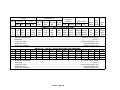
MODEL PZJ – 1,000 H.P. TRIPLEX MUD PUMP
17.03
585
2215
2639
185.5
14.69
504
1908
3060
215.1
13.59
466
1764
3310
232.7
12.53
430
1628
3592
252.5
10.52
361
1367
4274
300.5
8.70
298
1128
5000*
315.5*
7.04
242
916
5000*
315.5*
5.53
191
723
5000*
315.5*
Piston Load
Pounds
kg
101,548 46,061
101,548 46,061
101,548 46,061
101,548 46,061
101,548 46,061
98,175* 44,532*
79,522* 36,071*
62,832* 28,501*
Pump
RPM
Jackshaft
RPM
Input
HP
130
130
130
130
130
130
130
130
582
582
582
582
582
582
582
582
1000
1000
1000
1000
1000
967*
783*
619*
Weight Complete Pump .......................................................................................................................... 26,500 lbs. (12,020.19 kg)
Gear Ratio ............................................................................................................................................................................ 4.48 to 1
Length Over Skid ............................................................................................................................... 224.12 Inches (5692.648 mm)
Width Over Skid ............................................................................................................................................. 96 Inches (2438.0 mm
Width Over Jackshaft ............................................................................................................................. 80.20 Inches (2037.08 mm)
3
3
3
3
7
6 1/2
6
5 1/2
177.8
165.1
152.4
139.7
10
10
10
10
254
254
254
254
5.0
4.31
3.67
3.09
MODEL PZK – 1,350 H.P. TRIPLEX MUD PUMP
18.93
575
2177
3624
254.8 139,474
16.31
496
1878
4203
295.5 139,474
13.89
422
1508
4933
346.8 139,474
11.70
355
1344
5000*
351.5* 118,791*
63,264
63,264
63,264
53,884*
115
115
115
115
504
504
504
504
Weight Complete Pump ........................................................................................................................... 40,500 lbs. (18370.48 kg)
Gear Ratio .............................................................................................................................................................................. 4.5 to 1
Gear Ratio ............................................................................................................................................................................ 4.38 to 1
Length Over Skid ..................................................................................................................................... 222.5 Inches (5651.5 mm)
Width Over Skid ............................................................................................................................................. 96 Inches (2438.4 mm
Width Over Jackshaft ................................................................................................................................... 104 Inches (2641.6 mm
15-600
Page 13
1350
1350
1350
1150*
Cylinder
Qty.
3
3
3
3
Displacement
Diameter
Stroke
Inches
mm
Inches
mm
7
6 1/2
6
5 1/2
177.8
165.1
152.4
139.7
11
11
11
11
279.4
279.4
279.4
279.4
Gal. Per Liter Per Gal. Per Liter Per
Rev.
Rev.
Min.
Min.
5.50
4.74
4.04
3.40
Maximum
Pressure
PSI
kg/cm2
Piston Load
Pounds
kg
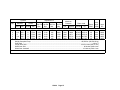
MODEL PZL – 1,600 H.P. TRIPLEX MUD PUMP
20.82
632
2392
3905
274.5 150,275 68,164
17.94
545
2063
4529
318.4 150,275 68,164
15.29
465
1760
5000*
351.5* 141,372* 64,126*
12.83
390
1476
5000*
351.5* 118,791* 53,884*
Pump
RPM
Jackshaft
RPM
Input
HP
115
115
115
115
504
504
504
504
1600
1600
1505*
1265*
Weight Complete Pump .......................................................................................................................... 40,500 lbs. (18,370.48 kg)
Gear Ratio ............................................................................................................................................................................ 4.38 to 1
Length Over Skid ..................................................................................................................................... 222.5 Inches (5651.5 mm)
Width Over Skid ............................................................................................................................................. 96 Inches (2438.4 mm
Width Over Jackshaft ................................................................................................................................... 104 Inches (2641.6 mm
3
3
3
3
3
7
6 1/2
6
5 1/2
5
177.8
165.1
152.4
139.7
127.0
11
11
11
11
11
MODEL PZL – 1,600 H.P. TRIPLEX MUD PUMP (HIGH PRESSURE)
279.4
5.5
20.82
632
2392
3905
274.5 150,300
279.4
4.74
17.94
545
2063
4529
318.4 150,300
279.4
4.04
15.29
465
1760
5316
373.7 150,300
279.4
3.40
12.83
390
1476
6328
444.8 150,300
279.4
2.80
10.60
322
1219
7500*
527.2* 147,262*
68,164
68,164
68,164
68,164
66,797*
115
115
115
115
115
504
504
504
504
504
Weight Complete Pump .......................................................................................................................... 41,750 lbs. (18,937.47 kg)
Gear Ratio ............................................................................................................................................................................ 4.38 to 1
Length Over Skid ..................................................................................................................................... 222.5 Inches (5651.5 mm)
Width Over Skid ............................................................................................................................................. 96 Inches (2438.4 mm
Width Over Jackshaft ................................................................................................................................... 104 Inches (2641.6 mm
15-600
Page 14
1600
1600
1600
1600
1565*
Cylinder
Qty.
3
3
3
3
3
Displacement
Diameter
Stroke
Inches
mm
Inches
mm
7
6 1/2
6
5 1/2
5
177.8
165.1
152.4
139.7
127.0
11
11
11
11
11
279.4
279.4
279.4
279.4
279.4
Gal. Per Liter Per Gal. Per Liter Per
Rev.
Rev.
Min.
Min.
5.50
4.74
4.04
3.40
2.80
Maximum
Pressure
PSI
kg/cm2
Piston Load
Pounds
kg
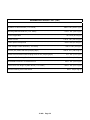
MODEL PXL – 2,000 H.P. TRIPLEX MUD PUMP
20.82
632
2392
4882
343.2 187,875 85,219
17.94
545
2063
5662
298.0 187,875 85,219
15.29
465
1760
6645
467.1 187,875 85,219
12.83
390
1476
7500*
527.2* 178,125* 80,797*
10.60
322
1219
7500*
527.2* 147,262* 66,797*
Pump
RPM
Jackshaft
RPM
Input
HP
115
115
115
115
115
504
504
504
504
504
2000
2000
2000
1895*
1565*
Weight Complete Pump .......................................................................................................................... 46,250 lbs. (20,978.63 kg)
Gear Ratio ............................................................................................................................................................................ 4.38 to 1
Length Over Skid ..................................................................................................................................... 222.5 Inches (5651.5 mm)
Width Over Skid ............................................................................................................................................. 96 Inches (2438.4 mm
Width Over Jackshaft ................................................................................................................................... 104 Inches (2641.6 mm
15-600
Page 15
SECTION 3
ROUTINE MAINTENANCE & SERVICE INSTRUCTIONS
Remove hood and crosshead inspection plates for
access to working parts. Before working on inside of
crankcase, it is necessary to drain the oil. Lube oil
pump mounting brackets and piping connections are
below the oil level.
Mark all parts during dismantling so they can be
returned to their original position during reassembly.
It is highly recommended that pump be removed to a
machine shop if major work is to be done on power
end.
spacer ring between the inner race and the shoulder
on the shaft.
If the jackshaft bearing is to be replaced, the outer
race and roller assembly can be driven or pressed out
of the bearing housing.
The jackshaft bearings should be replaced if any of the
rollers or races shows damage or if they are
excessively worn. A noisy bearing indicates bearing
damage, requiring replacement. Check clearances by
inserting feeler gauge between the roller and inner
race with bearing assembled on the shaft and in the
housing. This check can be made with the bearing
temporarily assembled out of the pump, but with inner
race on jackshaft. See recommended running
clearances on pages 28, 29, or 30.
To mount the new bearings, heat the inner race in oil
to about 300º F (148.8º C) and slip it in on the shaft
against the bearing spacer ring. Be certain the spacer
ring is in place with the chamfered end of the bore over
the large fillet on the jackshaft. The inner race and the
spacer are to be assembled snugly against the shaft
shoulder. The shaft can be reinstalled in the frame.
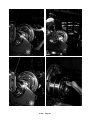
To mount a new oil seal wear sleeve, heat the sleeve
in oil to about 300º F (148.8º C) and slip it on the shaft.
See FIGURE 13, page 17.
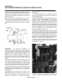
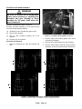
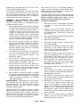
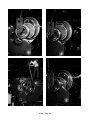
FIGURE 11 – JACKSHAFT BEARING INSTALLATION
JACKSHAFT - To remove the jackshaft, it is
necessary to remove all sheaves from the jackshaft.
Then remove bearing end plates and bearing housings
from both sides of pump. Support each end of
jackshaft while removing bearing housings. The
jackshaft can be moved horizontally until the pinion
teeth clear the teeth of the eccentric gear. The
jackshaft can now be removed from either side of the
pump.
The jackshaft bearings are of the straight roller type
with roller and cage assembly held in the flanged outer
race. The inner race is not flanged. The outer race and
roller assembly will slide over the inner race which
remains on the jackshaft. Both bearings are identical.
The straight roller bearings permit the jackshaft to float
endwise. Thrust loads are carried on the spherical
main bearings. Main bearings will be covered as a
separate item.
The safest way to remove the inner race of the
jackshaft bearing from the shaft is by the careful use of
heat. Do not overheat to the point where race is
discolored. Be careful not to damage the bearing
15-600
FIGURE 12 – JACKSHAFT REMOVAL/INSTALLATION FIXTURE
Page 16
PZG
Stroke:
7”
PZH
Stroke:
8”
PZJ
Stroke:
9”
PZK
Stroke:
10”
PZL
Stroke:
11”
PXL
Stroke:
11”
Dimensions
Inches
mm
Inches
mm
Inches
mm
Inches
mm
Inches
mm
Inches
mm
A
7.0
178
14.0
356
16.0
406
12.0
305
12.0
305
10.0
254
B Diameter
7.0
178
7.75
197.0
8.335
211.71
10.75
273.0
10.75
273.0
11.5
292.1
C
.38
9.6
.50
13.0
.50
13.0
1.75
44.5
1.75
44.5
1.00
25.4
6.25
159.0
6.878
6.880
174.70
174.75
7.378
7.680
187.40
187.45
9.504
9.505
241.40
241.42
9.504
9.505
241.40
241.42
10.007
10.005
254.17
254.12
E
------
------
2.00
51
2.00
51
2.9
74
2.9
74
2.50
63.5
F Diameter
6.004
6.006
152.50
152.55
6.752
6.754
171.50
171.55
7.252
7.254
184.20
184.25
9.252
9.254
235.00
235.05
9.252
9.254
235.00
235.05
9.755
9.753
247.77
247.72
G
------
------
3.00
76.0
3.00
76.0
1.4
36
1.4
36
2.50
63.5
D Diameter
H Diameter
------
------
6.88
175.0
7.38
187.5
10.0
254
10.0
254
10.2
259.08
J Diameter
6.004
6.006
152.50
152.55
6.752
6.754
171.50
171.55
7.252
7.254
184.20
184.25
9.252
9.254
235.00
235.05
9.252
9.254
235.00
235.05
9.755
9.753
247.77
247.72
FIGURE 13 – OIL SEAL WEAR SLEEVE INSTALLATION TOOL
To reassemble the jackshaft in the pump, it is
necessary to reverse procedure of removal. The teeth
of the pinion can mesh in only one direction, therefore,
the jackshaft is not interchangeable end for end in the
pump unless gear and eccentric assembly is also
reversed. Reversal of the complete gearset is
permissible after gear or pinion teeth become badly
worn. Since gear is not on centerline of the frame, it is
necessary to move the oil pump and filter from original
position to the opposite side of the frame and repipe as
required.
Required direction of rotation of the pump provides
that inner ends or apex of gear and pinion teeth lead.
This means that when viewing from the hood opening,
the inner ends of the gear teeth point upward toward
the jackshaft and the inner ends of the pinion teeth
point toward the gear. Gears may be reversed, but
direction of rotation of the pump MUST NOT BE
REVERSED. See paragraph “Lube Oil Pump” on the
15-600
following page. Pump should be run in the direction
shown on sectional view and indicated by arrow on
outline print and frame. Apex of teeth will follow after
gearset has been reversed.
After jackshaft is in place with the pinion in mesh with
the gear, install the bearing housings with the outer
bearing race and roller assemblies in them. Be careful
to keep dirt from the bearings during assembly. The
housing is to be started on the bearing and in the bore
of the frame and lightly driven in. Be sure the gasket is
on the housing. Long threaded studs may be used to
pull the housing into the frame bore. It is well to work
both housings at the same time after they have been
well started over the bearing inner race. This will
minimize end thrust on the gear teeth.
Before assembling bearing plates into the frame, the
bearing oil troughs should be installed. The bearing
housing can be rotated in the frame, making it easy to
Page 17
level oil trough properly. Top of oil trough is to be level.
The PZG pump does not have oil trough.
Outer oil seals are to be placed in the bearing end
plate after it is bolted to the bearing housing and
frame. Coat inside of oil seal liberally with bearing
grease. The seal is to be installed with garter spring to
inside, toward bearing. Permanently bolt jackshaft
bearing housings and their end plates to the frame.
LUBE OIL PUMP – The lube oil pump, part number
46C21, used in the PZG, PZH and PZJ pumps can be
reversed in direction when the complete gear sets are
reversed after the following procedure is completed.
Remove the oil pump with standard left hand helix
drive gear from the pump frame. Remove the drive
gear from the oil pump shaft.
Remove the end cap from the oil pump opposite the
shaft end, remove the drain plug screw opposite the oil
pump discharge port. Install the drain plug screw in the
hole provided 180o or opposite from the suction port.
Reverse the suction and discharge lines to the lube oil
pump and reverse the data tag “IN – ROTATION –
OUT”. The drain plug screw must be installed in the
pump body opposite the oil pump discharge port.
Replace the end cap.
Install the optional right hand helix drive gear on the oil
pump shaft. Install the oil pump and gear assembly on
alternate mounting pad in the pump sump to mesh with
reversed eccentric gear.
The lube oil pump, part numbers 46C58 (previous
production) and 201PAH188 (current production), used
in the PZK, PZL & PXL pumps can be reversed in
direction without modification to the pump. The oil flow
through the pump will reverse direction when shaft is
rotated in reverse.
Viewing the oil pump 46C58 from the shaft end,
rotating the shaft clockwise, the right hand pump
opening is the inlet. When rotating shaft
counterclockwise, the left hand opening is the inlet and
the right hand opening becomes the outlet.
When shaft rotation of the 201PAH188 oil pump
changes direction, the direction of flow changes
without changing inlet and outlet port positions.
When reversing the complete gear sets on PZK, PZL
and PXL pumps, the left hand helix pump drive gear
must be replaced with an optional right hand helix
drive gear. Install the oil pump and drive gear
assembly on the alternate sump mounting pad to mesh
with the reversed eccentric gear.
CONNECTING RODS – The connecting rods are split
into body and cap, and bolted together without shims.
y.
15-600
FIGURE 14 – CONNECTING ROD SUPPORT
This construction is used to simplify installation and/or
removal of eccentric and gear assembly.
The upper connecting rod bolt is inserted from the cap
side to avoid interference with jackshaft. The lower bolt
is inserted from body side to make nut easily
accessible.
Crosshead pins with bearing inner races can be
removed without disturbing the connecting rods on
PZG, PZH and PZJ pumps. On the PZK, PZL & PXL
pumps, the hood must be removed and the connecting
rods loosened from the cap and parted by about one
inch (25.4 mm) before the center crosshead pin will
clear the outside connecting rod.
Always protect crosshead slide in frame by placing a
block of wood under small end of connecting rod. If
slide should be accidently damaged, be certain to
stone damaged area so no metal projects above slide
surface. DO NOT USE EMERY CLOTH.
When caps are removed, the bodies of the connecting
rods can be supported by wiring or tying them to cap
screws temporarily screwed into hood ledge above
them. Do not damage hood gasket surface. See
FIGURE 14.
Remove eccentric bearing retainers from the
connecting rod body and cap before cap is removed.
Replace retainers after connecting rods have been
reassembled. Be sure to wire the cap screws securely.
Connecting rod bolt nuts are to be tightened to
recommended torque shown on pages 31 and 32. The
Pal locknuts are to be driven against nut by hand and
then tightened 1/3 to 1/2 turn.
Page 18
ECCENTRIC AND GEAR ASSEMBLY -
WARNING
Be sure to remove the oil pump drive
pinion when removing or replacing the
eccentric and gear asembly to avoid
bending the oil pump shaft when the
gear is removed.
Eccentric and shaft are made in one piece.
Eccentric and gear assembly is to be removed from
the frame for the following reasons:
(a) Assembly is to be reversed after gear is worn.
(b) Gear is to be replaced.
(c) One or more eccentric bearings are to be
replaced.
(d) Eccentric is to be replaced.
Procedure For Removal:
1. Remove connecting rod caps and support the
rods.
FIGURE 15 – ECCENTRIC GEAR ASSEMBLY SUPPORT
2.
Remove large main bearing plates from frame
and bearing cartridges.
3.
Remove frame clamp studs over main bearings.
4.
Remove frame spacer blocks by removing them
sideways, as they are keyed to frame. Be sure the
1" - 8 UNC THREAD
FOR EYEBOLT
1" - 8 UNC THREAD
FOR EYEBOLT
1.0
1.0
4.2
WELD
1.5
4.56
6.0
4.0
.4
4.5
25
32
2.0
5.5
3.0
WELD
.38
7.0
1.0
1.0
25 DRILL THRU
32 ONE HOLE
DRILL THRU
ONE HOLE
7
8 DRILL THRU
2 HOLES
7
8 DRILL THRU
2 HOLES
45F
1.75
.69 R
2.22
45F
2.12
.68 R
2.44
C75427
FOR PZG ONLY
4.44
7.9 R
1 18
C74625
FOR PZH ONLY
4.88
8.86 R
1 18
- 7 UNC THREAD
FOR EYEBOLT
1
1.0
5
WELD
2
1
3
5.5
WELD
2.0
8
6
4
- 7 UNC THREAD
FOR EYEBOLT
7.0
1
4.0
2
8
8
8.0
1"
25 DRILL THRU
32 ONE HOLE
1.0
29 DRILL THRU
32 ONE HOLE
7
8 DRILL THRU
2 HOLES
45F
2
1"
2 DRILL THRU
2 HOLES
3
16
45F
2.28
.88 R
7R
2
3
3.20
8
4
5
9
27
R
32
1
2
6.40
C73507
FOR PZJ ONLY
11.5 R
C74911
FOR PZK, PZL & PXL ONLY
FIGURE 16 – MAIN BEARING CARTRIDGE LIFITING & LOCATING DEVICES
(Dimensions Shown in Inches – See Figure 17, Page 20 for Metric Equivalents)
15-600
Page 19
METRIC EQUIVALENTS
Inches
3/8 (.375)........................................................................
.38 ..................................................................................
.68 ..................................................................................
.69 ..................................................................................
25/32 (.78125)................................................................
7/8 (.875)........................................................................
.88 ..................................................................................
29/32 (.90625)................................................................
1.0 ..................................................................................
1 1/8 (1.125)...................................................................
1.5 ..................................................................................
1.75 ................................................................................
2.0 ..................................................................................
2.12 ................................................................................
2 3/16 (2.1875)...............................................................
2.22 ................................................................................
2.28 ................................................................................
2.44 ................................................................................
2 3/4 (2.75).....................................................................
mm
9.525
9.652
17.272
17.526
19.844
22.225
22.352
23.019
25.4
28.575
28.1
44.45
50.8
53.848
55.563
56.388
56.912
61.976
69.85
Inches
3.................................................................................
3.20............................................................................
4.0..............................................................................
4.2..............................................................................
4.44............................................................................
4.5..............................................................................
4.56............................................................................
4.88............................................................................
5 1/8 (5.125) ..............................................................
5 1/2 (5.5)
6.0..............................................................................
6.40............................................................................
6.5..............................................................................
7.0..............................................................................
7.9..............................................................................
8.0..............................................................................
8.68............................................................................
9 17/32 (9.84375) ......................................................
11.5............................................................................
mm
76.2
81.28
101.6
106.68
112.776
114.3
115.824
123.952
130.175
139.7
152.4
162.56
165.1
177.8
200.66
203.2
220.472
250.031
292.1
FIGURE 17 – TABLE OF METRIC EQUIVANENTS FOR DIMENSIONS (INCHES)
spacer blocks are marked to assure reassembly in
original position.
5.
6.
Loosen main bearing retainer plate screws in
ends of eccentric shaft. Do not remove the
retainer plate screws. Leave about 1/4” (6 mm)
space between eccentric shaft and retainer plates.
Spread frame slot approximately 1/64” (.4 mm) by
means of hydraulic or screw jacks (FIGURE 15,
page 19). Be sure to protect faces of frame
slots against damage from jacks. This is
important.
7.
Support eccentric and gear assembly in original
position by means of a sling, hoist or blocks
(FIGURE 15, page 19).
8.
Connect a 10,000 PSI (703.1 kg/cm2)hydraulic oil
pump (BlackHawk P76 or equivalent) to 3/8” pipe
tap in end of eccentric shaft after removing
protective plug. There is a clearance hole through
the retainer plate.
9.
Hydraulic pressure will loosen bore of the main
bearing on the tapered shaft.
10. With bearing loose on the shaft taper, the retainer
plates should be removed. They are heavy, so
suitable provisions must be provided to handle
them. Lifting devices shown in FIGURE 16, page
19, are useful in disassembly as well as during
assembly.
11. Eccentric and gear assembly, with the connecting
rod bearings on it, can now be lifted and shifted to
remove it from the frame. Be sure to protect
frame slot faces with a sheet material to
prevent damage to them and to the tapered
eccentric shaft. THIS IS IMPORTANT.
15-600
It will be necessary to raise or lower and shift the
suspended connecting rods to clear the eccentric
during removal.
After eccentric assembly has been removed from
the frame, remove outer cam bearings from their
inner races. They might slide off and be damaged
or injure someone.
12. Set eccentric assembly in a clean place so work
can proceed on it.
13. It is essential that every effort be taken to protect
all roller bearing from dust and dirt by keeping
them wrapped in sheet plastic or clean paper. Be
certain to cover the bearings if they are to remain
out of the frame for hours, such as overnight.
ECCENTRIC CAM BEARINGS - These bearings are
mounted on, and remain with the eccentric and gear
assembly during dismantling and reassembly of the
power end. The bearings are of the cylindrical roller
type, with the rollers retained in the outer race. The
inner races are shrunk on the eccentric cams.
The outer races with rollers slide off the end or outer
eccentric cam bearing inner races. The center bearing
is slipped over the adjacent eccentric cam after its
bearing race has been removed.
Inner bearing races can be removed by heating evenly
all around with torches. If bearings are to be use again,
be careful no to discolor the inner race with excessive
heat. “Spit-frying” hot is sufficient. Handle with gloves.
The center bearing inner race is slipped over the
adjacent end cam while it is still hot and after the end
bearing inner race has been removed.
These bearings are not preloaded and must have
running clearance. Check with feeler at bottom and
Page 20
between inner race and rollers. See 28 thru 30 for
recommended running clearances.
Inner races are equipped with an end ring. They must
be mounted on the correct end of each inner race.
Refer to sectional view showing eccentric and bearings
for proper location of inner race end ring. Radius on
inside diameter of end ring must face out.
ASSEMBLY
OF
ECCENTRIC
AND
GEAR
ASSEMBLY IN FRAME - The following procedures
should be carefully followed in assembling eccentric
and gear assembly in frame.
1.
2.
3.
Install a pipe through eccentric and gear assembly
and place bearing carrier and bearing assemblies
on either end. With lifting devices shown in
FIGURE 18, page 22, lift the unit and turn the
eccentric so center throw is at the extreme top
position (see reference mark in photograph).
Carefully guide into position as shown. Be sure
teeth of eccentric gear are pointing in proper
direction to mesh with teeth of jackshaft.
Bar eccentric and gear assembly so reference
point on center throw moves away from operator
approximately 20º from vertical as shown in
FIGURE 19, page 22. Ease the assembly back
and down slightly, being careful not to damage
teeth of gear or lip of frame.
As eccentric moves into position, the connecting
rods must be lifted and guided into position as
they come in contact with the eccentric. See
FIGURE 20, page 22.
4.
Bar eccentric so reference point moves back
toward operator to approximately 20º his side of
vertical as shown in FIGURE 21, page 22.
5.
Ease eccentric back and lower into position as
connecting rods come to rest on eccentric. Care
must be taken as teeth of main gear come in
contact with teeth of jackshaft. Refer to FIGURE
22 and FIGURE 23, page 23.
6.
With eccentric in position as shown in FIGURE
24, page 23, a porta-power jack can now be used
to spread the frame for installation of the bearing
carrier and bearing assemblies as described
under “Main Bearings”.
MAIN BEARINGS - These bearings are of the doublerow spherical type. Inner race has a tapered bore.
Main bearings can be replaced without removing
eccentric assembly from the pump and without
disturbing connecting rods.
Remove bearings with cartridges from the eccentric
shaft and frame as outlined in procedure covering
removal of eccentric and gear assembly. Be sure to
support eccentric securely in its original location.
Remove lube oil pump gear to protect oil pump shaft
as main gear might move during this operation.
15-600
Main bearing is a slip fit in the bearing cartridge or
carrier, and can be readily removed. Remove inner
retainer ring from end of cartridge if it is necessary to
drive the bearing from the cartridge.
Antifriction bearings should not be removed from their
protective wrapping until ready to be mounted. Do not
remove protective grease from rollers of new
bearings. It will not contaminate crankcase oil.
Procedure For Mounting
1.
When ready to mount, unwrap bearing and stand
it upright on a clean flat surface with bore
horizontal.
2.
Determine and record internal clearance by
checking with feeler gauge between upper rollers
and inside diameter of outer race. Check both
rows of rollers.
3.
Wipe outside diameter of bearing clean and apply
a thin coat of crankcase oil.
4.
Wipe bore of bearing cartridge clean.
5.
Push bearing snugly onto taper of shaft by hand
only, without cartridge.
6.
Check and record bearing overhang with a depth
micrometer or with straight edge and feeler
blades. This can be done with eccentric out of the
frame as shown in FIGURE 25, page 23.
7.
Determine thickness of shim pack required for
drive-up by subtracting .067” (1.7018 mm) for
PZG and PZH, .075” (1.905 mm) for PZJ, or .090”
(2.286 mm) for PZK, PZL and PXL from the
bearing overhang. For example (Model PZJ): If
the overhang is .100” (2.54 mm), the shim pack
thickness is .100” (2.54 mm) minus .075” (1.905
mm) equals .025” (.635 mm).
8.
Lay bearing on a flat clean surface with small end
of bore down.
9.
Lower cartridge over bearing, using light blows
with a soft mallet if needed. Bearing cartridge is
interchangeable end for end.
10. Bolt retainer ring directly against upper end of
R.H. bearing cartridge. This will be at large end of
bearing bore. Wire cap screws.
11. Bolt retainer to upper end of L.H. cartridge with
1/8” (3.175 mm) spacer between. Wire cap
screws. Current models do not use retainer and
spacer on L.H. cartridge. R.H. bearing is secured
endwise. The L.H. bearing floats endwise within
the cartridge to allow for uneven expansion and
contraction of eccentric shaft and frame. Bearings
are not preloaded.
12. Apply a thin and uniform coating of micronized
graphite or light oil to bore of bearing and to
tapered portion of eccentric shaft.
Page 21
FIGURE 18
FIGURE 19
FIGURE 20
FIGURE 21
15-600
Page 22
FIGURE 22
FIGURE 23
FIGURE 24
FIGURE 25
15-600
Page 23
13. Mount shim pack on end of journal and assemble
bearing retainer plate.
14. Force bearing onto shaft taper by tightening cap
screws as evenly as possible.
15
22. Replace lube oil pump. Put the hood back in
place. Be sure the gasket is in good condition and
in proper location. Bolt down securely. Use grease
on frame flange to help keep hood gasket in
place.
Bearing retainer plate must be clamped solidly
against shims. It may be necessary to vary
thickness of shim pack slightly to keep internal
running clearances within the recommended
limits.
23. Do not forget to replace or renew the crankcase
oil. Now is a good time for an oil change and a
new filter element to protect the new bearings just
installed.
If excessive torque on retainer plate screws is
required, it may be necessary to resort to
hydraulic assistance. See Item 8 on Page 20.
CROSSHEAD PINS
Rotate bearing cartridges in frame so holes for
bearing end plate cap screws line up. The lifting
device shown in FIGURE 15 and FIGURE 16,
page 19, will automatically align holes.
1.
Bearing cartridge must enter bore in frame as
bearing is put on shaft. Use a soft mallet on end of
cartridge if necessary.
Procedure For Removal of Outer Crosshead Pins
Cut wire and remove retainer plate to crosshead
cap screws and use these as jack screws in
tapped holes in plate to pull pins. A little
persuasion with a drift driven against the
crosshead body and close to the large end of pin
will help loosen the pin.
Procedure For Removal of Center Crosshead Pin
16. Remove frame slot spreader jacks. Replace frame
slot spacers. Be certain block to frame keys are in
place. Replace frame slot clamp studs, washer
plates and nuts. Tighten nuts to approximately
500 foot-pounds (69.13 kg-m) only at this time. Be
sure ends of both bearing cartridges are flush with
frame faces.
1.
Remove outer crosshead next to large end of
center crosshead pin to give room to remove pin
from center crosshead. Protect crosshead slide in
frame with a block of wood.
2.
Rotate pump until center crosshead is at end of its
stroke toward fluid cylinder.
The end of L.H. bearing may not be flush with the
end of its cartridge as this is the floating bearing.
Plus or minus 1/16” (1.5875 mm), or less, is
satisfactory.
3.
Remove center crosshead pin as described above
for the two outer pins.
17. Tighten nuts on frame slot clamp studs a
minimum of 1/3 turn total (2 flats). This equals the
torque shown in the Torque Tables on pages 31
and 32.
PUSH RODS - Push rods can be removed from the
crossheads by working through handhole plates in the
sides of the frame and also through the oil stop
openings after the oil stop head assemblies have been
removed.
Be careful not to damage the highly polished surface
on which oil seals bear.
WARNING
It is important that these studs are
tightened as recommended to prevent
stud and/or frame breakage.
Push rods are stainless steel and should be protected
when the pump is painted. Paint will damage the oil
stop head seals.
WARNING
18. Bolt R.H. bearing end plat in place first.
19. Bolt L.H. bearing end plate in place.
20. Assemble the drive pinion on the shaft of the lube
oil pump.
21. Remove all tools and loose parts from the
crankcase. Remove the device use to support the
weight of the eccentric assembly.
15-600
Be sure to install the push rods with the
flat side and the word TOP to the top
side of the crosshead for proper
alignment of the push rod, piston rod,
piston and liner.
Page 24
in frame, or through crosshead inspection openings.
OIL STOP HEADS - Oil stop heads keep the
crankcase oil within the frame. They also keep mud
and liner washing fluids from entering the crankcase.
Oil stop packing consists of two identical seals
mounted in adaptors. They are not adjustable.
The inner seal lip is pointed inward toward the
crankcase to strip oil from the push rod. The outer seal
lip points outward toward liner to strip mud and/or
water from the push rod. Be certain seals are properly
installed.
B 76904
FIGURE 26 – INSTALLATION OF PUSH RODS
CROSSHEADS - Crossheads are one-piece
construction and run on replaceable bronze slides
bolted in the frame. Crossheads are made of ductile
iron.
Procedure For Removal
1. Remove oil stop head assemblies, crosshead pins
and push rods as described above.
2.
Slide the crossheads through the oil stop
openings in the frame and lift them clear. Be
careful to protect the shoe surfaces from damage.
CROSSHEAD SLIDES - The crosshead slides are cast
of tough bearing bronze. Top and bottom slides are
interchangeable and are bolted into the frame. Slides
are also interchangeable end for end.
The operating load is carried on the lower shoe and
slide when pump is run in prescribed direction.
It is unlikely that upper slides will even require
replacement unless damaged by accident.
It is necessary to remove the jackshaft in order to
reach the cap screws which hold the upper crosshead
slides to the frame on early models. Later models are
provided with openings on the outside of the frame to
reach and remove these cap screws and nuts.
Lower slides may eventually need to be replaced after
long wear or if damaged. It is advisable to remove the
crossheads as described above in order to reach the
countersunk head cap screws which secure the slides
to the frame. The nuts are on the outside and
underneath the frame.
Use of shims between the crosshead slides and the
frame is not recommended as they may fret through.
Use new slides instead of shimming.
Slides can be removed through oil stop head openings
15-600
The seal adaptors, with seals in them, can be slipped
off and on the push rods by removing the clamp
holding piston rods against the push rods and
separating the two flanges. Do not use a screwdriver or
drift to separate the push rod and piston rod flanges.
Turn the pump slightly.
It is essential that oil stop head seals be replaced at
the first indication of leakage. Oil leakage will be
indicated by oil collecting on top of the liner washing
water in the reservoir. If rig water is used for washing
and run to a waste area, it is difficult to check the
above method.
If oil leakage is serious it will show up in a lower oil
level in the crankcase. In this case oil must be added
to the crankcase as required until new oil stop seals
can be installed.
Leakage of mud and water into the crankcase will be
indicated by a milky appearance of the crankcase oil.
Mud will also be seen below oil stop heads on inside of
crankcase through crosshead inspection plate
openings.
When mud is found in crankcase, oil should be
changed. Drain and clean out crankcase before putting
in the new oil. Replace seals in oil stop heads before
running pump.
It is recommended that oil stop head seals be changed
every six months of operation, even though leakage is
not evident.
VALVE CHAMBERS - The PZ series and PXL pumps
are equipped with individual valve chambers
(cylinders).
Valve chambers are secured to frame with high tensile
strength studs. It is important that nuts on these studs
be checked occasionally for tightness. A loose nut will
eventually cause a stud to break under pulsating load.
These connecting studs extend through the liner clamp
flanges. Liner clamps are clamped by means of above
studs against the liner flanges and serve to clamp
liners tightly against valve chambers. A square rubber
Page 25
compound gasket seals end of liner against valve
chamber. When replacing a valve chamber it is
necessary to remove the discharge manifold. Also
remove screws holding suction manifold to the
chamber being replaced. Loosen, but do not remove
suction manifold screws in the other two chambers.
Suction manifold can be dropped enough to clear
gaskets. These members are to be securely bolted to
the new valve chamber before it is finally tightened
against frame connecting flange. Be sure manifold
gaskets are in place.
LINER CLAMP AND LINERS - When liner clamps are
reinstalled or replaced, it is advisable to check cylinder
to frame stud nuts and tighten if necessary. Refer to
pages 31 and 32 for proper torques.
Nuts holding liner clamps in place should not be
overtightened as distortion of the clamp and liner bore
may result. Recommended torque values are shown
on pages 31 and 32.
Change size of pistons and liners as volume and/or
pressure requirements change. See rating charts on
pages 12 thru 15.
Liners are replaced by removing the liner clamp. Liners
should be cleaned and oiled after removal to protect
against rusting during storage, so they can be used
again.
Pump liners are to be clean both inside and out when
installed. Also clean the liner clamp bore and lightly oil
all surfaces.
Use new gaskets when installing liners and be sure to
clean all surfaces against which the gaskets fit. Liners
or valve chambers may be cut by leaking gaskets.
PISTONS - Single-acting pistons consist of a steel
piston body with insert retained by a washer and snap
ring.
Pistons, with piston rods, can be removed or installed
through suction valve opening after valve upper guide
is removed by turning it 90_. Valve spring must also be
removed. 7” pistons on PZG, PZH and PZJ pumps
must be removed through frame. In the 7500 PSI high
pressure fluid cylinders, 6” diameter is the maximum
that can be removed through the suction valve
opening. Larger diameters must be removed through
the frame.
It is recommended that a piston and rod assembly be
kept ready for replacement. This is a practical timesaver.
PISTON ROD - Piston rods are manufactured of high
carbon steel. They are electrolytically plated to protect
against corrosion. They are provided with a knurled
15-600
section so rod can be held while tightening piston nut.
It is important that piston rod nut be tightened to
recommended torque shown on pages 31 and 32.
Piston rod to piston fit is straight. Piston fits against
flange on piston rod with on “O” ring gasket to prevent l
connecting flanges and pilots. DO NOT use a
screwdriver or cold chisel to separate the flanges - turn
the pump slightly.
For pumps with threaded piston rod to push rod
connection, tighten to torque specified on pages 31
and 32.
PISTON WASHING SYSTEM - The piston washing
system is vital to the satisfactory performance and life
of pistons and liners. The complete system must be
kept in good operating condition. Washing fluid should
be maintained in good condition and should be
replaced when contaminated to the point where free
circulation is impaired. This is of utmost importance
and should be impressed upon all operators of the
pump.
Water supply lines should be permanently attached to
the openings provided in the circulating pump and the
tank. Water is then quickly available as a washing fluid
or to flush out the lines by operating the proper valves
in the piping system.
The piston washing fluid may be varied according to
conditions and operator’s preference. Water makes a
suitable washing fluid under most conditions. Good
results can be obtained using water with one-half
gallon (1.9 liters) of soluble oil per tank of water within
the closed system. A light oil gives good results under
some conditions, and can be used under severe
freezing conditions.
The more fluid circulated, the better; however, it should
be regulated by a valve in discharge line of the
centrifugal circulating pump to prevent splashing and
being blown about.
MAINTENANCE OF VALVES - In order to keep the
pump in its best operating condition, it is necessary to
examine the suction and discharge valves occasionally
to see that excessive wear or cutting by the slush or
mud has not impaired their efficiency. Any worn or
damaged parts should be replaced.
This is especially true with regard to the inserts.
Standard inserts are made from urethane and are the
part of the valve which should be changed most
frequently. They are much cheaper than the valves and
seats, and if the inserts are renewed as soon as they
begin to fail, the more expensive steel parts will last
much longer. Routine inspection of valves every two or
three days is recommended.
Page 26
When removing a worn valve seat, use the GardnerDenver puller powered with a hydraulic jack. Be careful
to chain or tie the jack down as it will jump violently
when the valve seat lets go. If it becomes necessary to
resort to the use of heat or a cutting torch to remove a
valve seat, the services of a man experienced in these
operations is necessary.
Do not put a used valve assembly on a new seat
unless it is in practically a new condition. Be sure to
replace a doubtful insert to protect seat and bumper.
Before putting new seats in the pump, the tapered bore
in the valve seat deck of the cylinder must be
thoroughly cleaned with a wire brush. Wire brush
should be used around the bore rather than up and
down. Wipe the bore clean and do not use oil or
grease. The bore must be clean and dry or seat may
not seat properly. The valve seat tapered surface must
be cleaned and dry before assembling in cylinder deck.
When installing valves, wipe all sealing surfaces clean,
put the gasket carefully in place in the valve chamber
and install cover plate. Be sure gasket is not twisted or
extruded. Tighten valve cover lock securely by using a
bar and hammer.
Place the new seat in the bore. Use an old valve
bumper or a block of hard wood and drive with a
sledge to a snug initial fit. The pressure load on the
valve in operation will drive the seat home. Never
reuse an old seat once it has been removed from a
cylinder, as it may not fit solidly in the valve deck.
Replace the valve guide or valve guide bushings if
worn. Replace the valve spring if it is worn, corroded,
distorted, or below normal tension. Valves are provided
with stainless steel springs for maximum operating life.
A broken spring will cause rapid wear of valve guides
and should be replaced. It will also cause wear on
suction valve guide mounting lugs inside the valve
chamber (cylinder).
15-600
It requires experience and judgment to determine if
valve parts should be replaced or not. Valves are
cheaper than downtime.
The life of the valves will be lengthened if the mud
tanks are kept clean. In may cases foreign objects are
caught under the valves, thereby holding them open
and causing rapid cutting of the seats and valves.
SUCTION STRAINER - A suction strainer is
recommended for the suction line of every pump to
protect the valves.
The current PZ series and PXL pumps are not
equipped with a suction strainer. A commercial
strainer, however, may be installed in the suction line
ahead of the pump.
The early PZJ pumps were equipped with a perforated
metal strainer inside the suction manifold. This strainer
can be removed from the end opposite the suction line
for inspection and cleaning. Strainer should be
checked if the pump starts to run rough, with violent
discharge pulsations. One or more cylinders may have
their suction obstructed by debris in the strainer.
Page 27
SECTION 4
DIMENSIONS & RUNNING CLEARANCES
PZG
RECOMMENDED RUNNING CLEARANCES
PZH
Inches
mm
Inches
Max
mm
Min
Max
Min
Max
Min
Min
Max
Crosshead to slide
.020
.037
.508
.940
.020
.037
.508
.940
Main Bearing
.001
.004
.025
.102
.003
.006
.076
.152
Jackshaft Bearing
.001
.006
.025
.152
.002
.006
.051
.152
Crosshead Pin Bearing
.001
.006
.025
.152
.001
.005
.025
.127
Connecting Rod to Eccentric Bearing
.001
.011
.025
.279
.002
.010
.051
.254
Oil Pump Pinion to Main Gear – Backlash
.010
.015
.254
.381
.010
.015
.254
.381
Jackshaft to Main Gear - Backlash
.010
.015
.254
.381
.010
.020
.254
.508
.0013
.0017
.0330
.0432
.0007
.0031
.0178
.0787
Tight
Loose
Tight
Loose
Tight
Loose
Tight
Loose
.0017
.0037
.0432
.0940
.0020
.0043
.0508
.1092
Tight
Tight
Tight
Tight
Tight
Tight
Tight
Tight
.004
.000
.102
.000
.0034
.0000
.0889
.0000
(AFTER ASSEMBLY)
MANUFACTURING FITS
Jackshaft Bearing OD in Housing
Jackshaft Bearing on Shaft
Connecting Rod to Eccentric Bearing:
OD in Connecting Rod
Tight
ID on Eccentric
Tight
Tight
Tight
.0072
.0110
.1829
.2794
.0080
.0115
.2032
.2921
Tight
Tight
Tight
Tight
Tight
Tight
Tight
Tight
.0027
.0000
.0686
.0000
.0022
.0000
.0559
.0000
Crosshead Pin Bearing:
OD in Connecting Rod
Tight
ID in Crosshead Pin
Main Bearing OD in Cartridge
Main Bearing on Shaft
Tight
Tight
Tight
.0005
.0025
.0127
.0635
.0005
.0025
.0127
.0635
Tight
Tight
Tight
Tight
Tight
Tight
Tight
Tight
.0002
.0036
.0051
.0914
.0002
.0036
.0051
.0914
Loose
Loose
Loose
Loose
Loose
Loose
Loose
Loose
Tapered Bore
Tapered Bore
Tapered Bore
Tapered Bore
Axial Takeup
Axial Takeup
Axial Takeup
Axial Takeup
.067 Average
1.702 Average
.067 Average
1.702 Average
15-600
Page 28
PZJ
RECOMMENDED RUNNING CLEARANCES
PZK
Inches
mm
Inches
Min
Max
Min
Max
Min
Crosshead to slide
.020
.037
.508
.940
.025
Main Bearing
.005
.008
.127
.203
Jackshaft Bearing
.002
.004
.051
Crosshead Pin Bearing
.002
.005
Connecting Rod to Eccentric Bearing
.002
Oil Pump Pinion to Main Gear – Backlash
Jackshaft to Main Gear - Backlash
Max
mm
Min
Max
.042
.635
1.067
.003
.008
.076
.203
.102
.002
.008
.051
.203
.025
.127
.001
.007
.025
.178
.008
.025
.203
.002
.011
.051
.279
.010
.015
.254
.381
.010
.015
.254
.381
.010
.020
.254
.508
.010
.020
.254
.508
.0007
.0031
.0178
.787
.0014
.0025
.0356
.0635
Tight
Loose
Tight
Loose
Tight
Loose
Tight
Loose
.0020
.0043
.0508
.1092
.0020
.0044
.0508
.1118
Tight
Tight
Tight
Tight
Tight
Tight
Tight
Tight
.004
.000
.102
.000
.004
.000
.102
.000
(AFTER ASSEMBLY)
MANUFACTURING FITS
Jackshaft Bearing OD in Housing
Jackshaft Bearing on Shaft
Connecting Rod to Eccentric Bearing:
OD in Connecting Rod
Tight
ID on Eccentric
Tight
Tight
Tight
.009
.013
.229
.330
.011
.015
.2794
.381
Tight
Tight
Tight
Tight
Tight
Tight
Tight
Tight
.0027
.0000
.0686
.0000
.0018
.0040
.0457
.1016
Crosshead Pin Bearing:
OD in Connecting Rod
Tight
ID in Crosshead Pin
Main Bearing OD in Cartridge
Main Bearing on Shaft
Tight
Tight
Tight
.0005
.0025
.0127
.0635
.0010
.0032
.0254
.0813
Tight
Tight
Tight
Tight
Tight
Tight
Tight
Tight
.0002
.0036
.0051
.0914
.0002
.0036
.0051
.1321
Loose
Loose
Loose
Loose
Loose
Loose
Loose
Loose
Tapered Bore
Tapered Bore
Tapered Bore
Tapered Bore
Axial Takeup
Axial Takeup
Axial Takeup
Axial Takeup
.074 Average
1.880 Average
.090 Average
2.286 Average
15-600
Page 29
PXL
RECOMMENDED RUNNING CLEARANCES
Inches
mm
Min
Max
Min
Max
Crosshead to slide
.025
.042
.635
1.067
Main Bearing
.003
.008
.076
.203
Jackshaft Bearing
.002
.008
.051
.203
Crosshead Pin Bearing
.000
.006
.000
.152
Connecting Rod to Eccentric Bearing
.000
.010
.000
.254
Oil Pump Pinion to Main Gear – Backlash
.010
.015
.254
.381
Jackshaft to Main Gear - Backlash
.010
.020
.254
.508
.0014
.0025
.0356
.0635
Tight
Loose
Tight
Loose
.0020
.0044
.0508
.1118
Tight
Tight
Tight
Tight
.004
.000
.102
.000
(AFTER ASSEMBLY)
MANUFACTURING FITS
Jackshaft Bearing OD in Housing
Jackshaft Bearing on Shaft
Connecting Rod to Eccentric Bearing:
OD in Connecting Rod
Tight
ID on Eccentric
Tight
.0110
.0150
.2794
.381
Tight
Tight
Tight
Tight
.0018
.0040
.0457
.1016
Crosshead Pin Bearing:
OD in Connecting Rod
Tight
ID in Crosshead Pin
Main Bearing OD in Cartridge
.0010
.0032
.0254
.0813
Tight
Tight
Tight
Tight
.0002
.0036
.0051
.1321
Loose
Loose
Loose
Loose
Main Bearing on Shaft
15-600
Tight
Page 30
Tapered Bore
Tapered Bore
Axial Takeup
Axial Takeup
.090 Average
2.286 Average
RECOMMENDED TORQUES – "PZ MODELS" (DRY)
Cylinder To Frame Stud Nut:
PZG, PZH & PZJ (1-1/4” Studs)
1800 Ft.Lbs. (248.87 kg-m)
PZG, PZH & PZJ (7/8” Studs)
600 Ft. Lbs. (82.98 kg-m)
PZK & PZL (1-1/4” Studs)
1800 Ft. Lbs. (248.87 kg-m)
Discharge Manifold Stud Nut:
PZG, PZH & PZJ (1” Studs)
600 Ft. Lbs. (82.96 kg-m)
PZK & PZL (LP) (1” Studs)
600 Ft. Lbs. (82.96 kg-m)
PZK & PZL (HP) (1-1/4” Studs)
1150 Ft. Lbs. (159.0 kg-m)
Connecting Rod Bolt
600 Ft. Lbs. (82.96 kg-m)
Piston Rod Nut
1100 Ft. Lbs. (152.09 kg-m)
Frame Spacer Clamp Studs:
PZG & PZH
600 Ft. Lbs. (82.96 kg-m)
PZJ, PZK & PZL
1600 Ft. Lbs. (221.22 kg-m)
Liner Clamp to Frame Stud Nut:
PZG, PZH & PZJ (1-1/4” Studs)
750 Ft. Lbs. (103.7 kg-m)
PZK & PZL (LP) (1-1/4” Studs)
750 Ft. Lbs. (103.7 kg-m)
PZK & PZL (HP) (1-1/4” Studs)
1400 Ft. Lbs. (193 kg-m)
Piston Rod to Extension Rod (Threaded Style)
1000 Ft. Lbs. (138.26 kg-m)
2-Piece PZK & PZL (HP) Piston Rod Stud (Coupling Style)
1000 Ft. Lbs. (138.26 kg-m)
Piston Rod to Extension Rod Coupling Screw or Nut (Coupling Style)
75 Ft. Lbs. (10.37 kg-m)
Crosshead Pin Retaining Plate Screw
370 Ft. Lbs. (51.17 kg-m)
Crosshead Extension to Crosshead Screw
220 Ft. Lbs. (30.43 kg-m)
Valve Cover Lock Ring to Cylinder Screw:
PZG, PZH & PZJ (1” Studs)
900 Ft. Lbs. (124.4 kg-m)
PZK & PZL (LP) (1” Studs)
900 Ft. Lbs. (124.4 kg-m)
PZK & PZL (HP) (1-1/4” Studs)
1600 Ft. Lbs. (221.2 kg-m)
Eccentric Bearing Cover Plate Screw
PZG, PZH & PZJ
260 Ft. Lbs (35.9 kg-m)
PZK & PZL
400 Ft. Lbs (55.3 kg-m)
15-600
Page 31
RECOMMENDED TORQUES -"PXL " (DRY)
CylinderTo Frame Stud Nut (1-1/4" Studs) ..........................................................................1800 Ft.Lbs. (248.87 kg-m)
Discharge Manifold Stud Nut (1-1/4" Studs) .........................................................................1150 Ft. Lbs. (159.0 kg-m)
ConnectingRodBolt ........................................................................................................................ 700 Ft.Lbs.(96.78kg-m)
Piston Rod Nut..........................................................................................................................1100 Ft. Lbs. (152.09 kg-m)
Frame Spacer Clamp Studs ......................................................................................................1600 Ft.Lbs.(221.22kg-m)
Liner Clamp to Frame Stud Nut (1-1/4" Studs) ........................................................................ 1400 Ft. Lbs. (193 kg-m)
2-Piece (HP) Piston Rod Stud (Coupling Style) .................................................................1000 Ft. Lbs. (138.26 kg-m)
Piston Rod to Extension Rod Coupling Screw or Nut (Coupling Style) ................................ 75 Ft. Lbs. (10.37 kg-m)
Crosshead Pin Retaining Plate Screw ......................................................................................... 370 Ft.Lbs.(51.17kg-m)
Crosshead Extension to Crosshead Screw............................................................................. 220 Ft. Lbs. (30.43 kg-m)
Valve Cover Lock Ring to Cylinder Screw (1-1/4" Studs) ...................................................1600 Ft. Lbs. (221.2 kg-m)
Eccentric Bearing Cover Plate Screw ............................................................................................ 400 Ft. Lbs(55.3kg-m)
15-600
Page 32
PRODUCT WARRANTY
GARDNER DENVER PETROLEUM PUMPS
GENERAL PROVISIONS AND LIMITATIONS
Gardner Denver (the "Company") warrants to each
original retail purchaser ("Purchaser") of its new
products, assemblies or parts from the Company or its
authorized distributors that such products are, at the
time of delivery to the Purchaser, made with good
material and workmanship. No warranty is made with
respect to:
1. Any product which has been repaired or
altered in such a way, in the Company's
judgment, as to affect the product adversely.
2. Any product which has, in the Company's
judgment, been subject to negligence,
accident, or improper storage, improper
installation, operation or application.
(Examples: over-pressure, sand-outs,
cavitation, corrosion, erosion or degradation).
3. Any product which has not been operated or
maintained in accordance with the
recommendations of the Company.
4. Components or accessories manufactured,
warranted and serviced by others.
5. Any reconditioned or prior owned product.
Claims for items described in (4) above should be
submitted directly to the manufacturer.
WARRANTY PERIOD
The Company's obligation under this warranty is
limited to repairing or, at its option, replacing, during
normal business hours at an authorized service facility
of the Company, any part or assembly which in the
Company’s judgment proved to have unsatisfactory
material or workmanship within the applicable
Warranty Period as follows.
Except for the products or components listed below,
and subject to the limitations and restrictions set forth
in the “Disclaimer” section set forth below, the
Warranty Period for all products is 1,250 hours of
operation or three (3) months after start-up, not to
exceed 120 days after delivery to Purchaser,
whichever occurs first. The exceptions are as follows:
1. Power end is warranted for twelve (12) months
from date of start-up or eighteen (18) months
from date of delivery to the Purchaser,
whichever occurs first.
2. Forged steel fluid cylinders are warranted for
materials and workmanship for 6 months from
the date of installation or 18 months from the
date of delivery to the purchaser, which ever
occurs first.
15-600
3. Repairs are warranted for 90 days from the
date of delivery, for the workmanship and
materials of the new parts installed.
4. Weld repaired fluid ends and weld repaired
components are not warranted.
5. Expendable fluid end parts, including, but not
limited to, valves, valve parts, packing, liners
and pistons, are not covered by this warranty
due to variable abrasive nature of material
pumped.
PRESERVATION ASSEMBLIES DESTINED FOR
STORAGE
In order for warranty acceptance any pump
assembly not immediately installed or destined to be in
storage or in transit for extended periods of time must
be prepared for storage as defined in the Company’s
Long Term Storage Procedure. This includes but is
not limited to:
Drain and thoroughly clean inside power end
crankcase.
Spray rust inhibiting oil on all bearing, machined
and inside surfaces of the power end.
Induce clean gear oil into any circulating pump,
filter, heat exchanger and piping.
Remove valves, seats and plungers from the fluid
end. Thoroughly clean and dry these parts and all
internal surfaces. Coat all cylinder bores, valve
covers and reusable expendable parts with rust
preventative.
Flush all water, and contaminants from pump,
tanks, hoses and spray nozzles. Spray all
components with a rust inhibiting oil.
Rotate pump every 30 days to insure bearings are
oiled.
At the expense of the Purchaser, any product
properly preserved must be inspected by an
authorized agent of the Company, prior to the
Company, granting any extended warranty beyond
that stated in this warranty.
LABOR TRANSPORTATION AND INSPECTION
The Company will provide labor, by Company
representative or authorized service personnel, for
repair or replacement of any product or part thereof
which in the Company's judgment is proved not to be
as warranted. Labor shall be limited to the amount
specified in the Company's labor rate schedule. Labor
costs in excess of the Company rate schedules caused
by, but not limited to, location or inaccessibility of the
equipment, or labor provided by unauthorized service
personnel is not provided for by this warranty.
Page 33
PRODUCT WARRANTY
GARDNER DENVER PETROLEUM PUMPS
All costs of transportation of product or parts
claimed not to be as warranted and, of repaired or
replacement parts to or from such service facility shall
be borne by the Purchaser. The Company may require
the return of any part claimed not to be as warranted to
one of its facilities as designated by the Company,
transportation prepaid by the Purchaser, to establish a
claim under this warranty.
Replacement parts provided under the terms of this
warranty are warranted for the remainder of the
Warranty Period of the product upon which installed to
the same extent as if such parts were original
components.
The Company may request a root cause analysis
be performed in-order to identify if a request for
warranty claim meets the requirements of this
warranty.
DISCLAIMER
Except as to title, the foregoing warranty is the sole
and exclusive warranty of the Company.
The
Company hereby extends other manufactures’
warranty or guaranties, if any given to Company by
such manufacturer, but only to the extent the Company
is able to enforce such warranty or guaranties. The
Company has not authorized any party to make any
representation or warranty other than as expressly set
forthherein.
SELLER HEREBY DISCLAIMS AND
EXCLUDES ANY OTHER EXPRESS, IMPLIED OR
STATUTORY
WARRANTIES,
ARISING
BY
OPERATION OF LAW OR OTHERWISE, INCLUDING,
WITHOUT LIMITATION, ANY WARRANTIES OF
MERCHANTABILITY
OR
FITNESS
FOR
A
PARTICULAR PURPOSE. COMPANY MAKES NO
WARRANTIES OR REPRESENTATIONS OF ANY
KIND WHATSOEVER (EXPRESS, IMPLIED OR
STATUTORY), OF LAW OR OTHERWISE, ON ANY
EQUIPMENT,
COMPONENT
PARTS
OR
ACCESSORIES SOLD HEREUNDER WHICH, ARE
NOT MANUFACTURED BY COMPANY.
NOTWITHSTANDING ANYTHING HEREIN TO
THE CONTRARY, THE FOREGOING WARRANTY
SHALL BE THE SOLE AND EXCLUSIVE REMEDY
AVAILABLE TO THE PURCHASER. UNDER NO
15-600
CIRCUMSTANCES, WHETHER IN CONTRACT,
TORT OR OTHERWISE, SHALL THE COMPANY’S
TOTAL LIABILITY ARISING IN CONNECTION WITH
ANY PURCHASE ORDER EXCEED THE AMOUNT
OF ANY SALES OR OTHER PROCEEDS RECEIVED
PURSUANT THERETO. IN ADDITION, UNDER NO
CIRCUMSTANCES, WHETHER IN CONTRACT,
TORT OR OTHERWISE, SHALL THE COMPANY BE
LIABLE FOR LIQUIDATED, SPECIAL, INDIRECT,
INCIDENTAL, EXEMPLARY, OR CONSEQUENTIAL
DAMAGES, EXPENSES OR COSTS, INCLUDING,
WITHOUT LIMITATION, LOST PROFITS OR
FACILITY DOWNTIME, HOWEVER CAUSED AND
EVEN IF THE POTENTIAL OF SUCH DAMAGES
WAS DISCLOSED AND/OR KNOWN.
No statement, representation, agreement, or
understanding, oral or written, made by any agent,
distributor, representative, or employee of the
Company which is not contained in this Warranty will
be binding upon the Company unless made in writing
and executed by an officer of the Company.
This warranty shall not be effective as to any claim
which is not presented within 30 days after the date
upon which the product is claimed not to have been as
warranted. Any action for breach of this warranty must
be commenced within one year after the date upon
which the cause of action occurred.
Any adjustment made pursuant to this warranty
shall not be construed as an admission by the
Company that any product was not as warranted.
WARRANTY REQUESTS
Products to be returned for warranty analysis shall be
approved for return in writing by the Company prior to
shipment. All requests for product return shall be
submitted by email. Facsimile or letter to:
Warranty Department
c/o Gardner Denver Petroleum Pumps
4747 South 83rd East Avenue
Tulsa, Oklahoma 74145
Email: [email protected]
Facsimile: (918) 664-6225
Page 34
For additional information contact your local representative or
Gardner Denver Compressor and Pump Division,
1800 Gardner Expressway, Quincy, Illinois 62301
Customer Service Department Telephone:
(800) 682-9868 FAX: (217) 224-7814
Sales and Service in all major cities.
Specifications subject to change without notice.
Copyright © 1999 Gardner Denver, Inc.
http://www.gardnerdenver.com
Litho in U.S.A.
For parts information, contact Gardner Denver,
Master Distribution Center, Memphis, TN
Telephone: (800) 245-4946 FAX: (901) 542-6159