1
GARDNER DENVER®
300WPD996 Revision B
April 2005
OPI-600
WELL SERVICING PUMP
OPERATING AND
SERVICE MANUAL
ECN 1025325
OPI-600
WELL SERVICING PUMP
MAINTAIN PUMP RELIABILITY AND PERFORMANCE WITH
GENUINE GARDNER DENVER
PARTS AND SUPPORT SERVICES
Gardner Denver® genuine pump parts are manufactured to design tolerances and are developed for
optimum dependability. Design and material innovations are the result of years of experience with
hundreds of different pump applications. Reliability in materials and quality assurance is incorporated
in our genuine replacement parts.
Your authorized Gardner Denver Sales Office offers all the backup you ll need. The Fort Worth
Manufacturing Facility maintains a large inventory of genuine parts.
Gardner Denver supports your needs with these services:
1.
Trained parts specialists to assist you in selecting the correct replacement parts.
2.
Repair and maintenance kits designed with the necessary parts to simplify servicing your pump.
Authorized service technicians are factory trained and skilled in pump maintenance and repair. They
are ready to respond and assist you by providing fast, expert maintenance and repair services.
For the location of your local authorized Gardner Denver distributor, refer to the yellow
pages of your phone directory or contact:
Factory (Tulsa):
Gardner Denver Well Servicing Pumps
4747 South 83rd East Avenue
Tulsa, Oklahoma 74145
Service Center (Odessa):
Chaparral
2121 West 44th Street
Odessa, Tx 79768
Service Center (Ft. Worth):
Geoquip
7533 Kathy Lane
Ft. Worth, Texas 76126
Phone:
(918) 664-1151
(800) 738-8099
Phone:
(432) 366-5433
(800) 368-1134
Phone:
(817) 249-6400
(800) 824-0271
Fax:
(918) 664-6225
Fax:
(432) 363-9940
Fax:
(817) 249-6401
INSTRUCTIONS FOR ORDERING REPAIR PARTS
When ordering parts, specify Pump MODEL and SERIAL NUMBER (see nameplate on unit).
The Serial Number is also stamped on top of the fluid end connecting plate of the frame (cradle
area).
All orders for Parts should be placed with the Tulsa or Ft. Worth facility.
Where NOT specified, quantity of parts required per pump or unit is one (1); where more than
one is required per unit, quantity is indicated in parenthesis. SPECIFY EXACTLY THE NUMBER
OF PARTS REQUIRED.
Page i
FOREWORD
Gardner Denver® pumps are the result of advanced engineering and skilled manufacturing. To
be assured of receiving maximum service from this pump the owner must exercise care in its
operation and maintenance. This book is written to give the operator and maintenance personnel
essential information for day-to-day operation, maintenance and adjustment. Careful adherence
to these instructions will result in economical operation and minimal downtime.
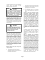
DANGER
Danger is used to indicate the presence of a hazard, which will cause severe
personal injury, death or substantial property damage if the warning is ignored.
WARNING
Warning is used to indicate the presence of a hazard, which can cause severe
personal injury, death or substantial property damage if the warning is ignored.
CAUTION
Caution is used to indicate the presence of a hazard, which will or can
minor personal injury or property damage if the warning is ignored.
NOTICE
Notice is used to notify people of installation, operation or maintenance
information which is important but not hazard related.
Page ii
cause
TABLE OF CONTENTS
Maintain Pump Reliability and Performance with Genuine Gardner Denver Parts and
Support Services................................................................................................................ i
Instructions For Ordering Repair Parts...................................................................................... i
Foreword .................................................................................................................................... ii
Index .......................................................................................................................................... iv
List of Illustrations ...................................................................................................................... v
Section 1, Danger Notices ......................................................................................................... 1
Section 2, Design, Description and Specifications .................................................................... 9
Section 3, Preparation, Operation and Maintenance................................................................. 13
Section 4, Service Procedures .................................................................................................. 20
Section 5, Trouble-Shooting ...................................................................................................... 30
Section 6, Rebuilding Data, Recommended Running Clearances ........................................... 36
Warranty..................................................................................................................................... 38
{ TC }
Page iii
INDEX
Charging Pump Requirement .......................13
Plunger Packing Lubrication
Recommendation Chart ....................... 19
Covers and Guards, Danger Notice................2
Plungers and Packing Replacement............ 22
Crankshaft.....................................................11
Power End.................................................... 10
Crosshead Assembly ....................................11
Power End Internal Lube Sytem .................. 11
Daily Routine Maintenance ...........................18
Power End Lubrication System .................... 14
DANGER NOTICES, SECTION 1 ..................1
Power End Service....................................... 23
DESIGN DESCRIPTION AND
SPECIFICATIONS, SECTION 2.............9
Preparation after Shipping and Storage....... 13
Equipment Moving and Lifting.........................2
PREPARATION, OPERATION AND
MAINTENANCE, SECTION 3 .............. 13
Flammable, Hot, cold or Corrosive Fluid
Pumping, Danger Notice.........................5
Pressurized Pump Systems, Danger Notice.. 3
Fluid End Installation.....................................21
Pump Design................................................ 10
Fluid End .......................................................11
Pump Mounting Instructions......................... 13
Fluid End Removal........................................20
Quarterly Routine Maintenance Schedule ... 18
Fluid End Service..........................................20
Rebuilding Data............................................ 36
Gearbox ........................................................11
General Requirements and Safety Rules .....20
REBUILDING DATA, RUNNING
CLEARANCES AND TORQUES,
SECTION 6 .......................................... 36
General Specifications ..................................12
Repair Parts, Ordering Instructions..................i
High Pressure Liquid Jetting, Blasting
and Cleaning, Danger Notice .................6
Running Clearances
Actual....................... 36
SERVICE PROCEDURES, SECTION 4 ...... 20
Hydraulic Puller, Danger Notice......................2
Startup and New Pump Run-In Procedure .. 16
Introduction .....................................................9
Torque Specifications................................... 37
Lube Pump Suction Piping Sizing and..........14
Requirements
TROUBLE-SHOOTING, SECTION 5........... 30
Lube Schematic ............................................15
Valves and Seats Replacement ................... 22
Lube System Pump.......................................14
Valve Seat Pulling, Danger Notice ..................2
Monthly Routine Maintenance Schedule ......18
Warranty ....................................................... 38
Performance Rating, OPI-600 ......................12
Wedge Puller, Danger Notice..........................2
Periodic Routing Maintenance Schedule......18
Plunger/Packing Lubrication .........................16
Page iv
LIST OF ILLUSTRATIONS
Figure #
Description
Page
Figure 2-1
OPI-600 Pump........................................................................................... 9
Figure 2-2
OPI-600 Power End Section ..................................................................... 10
Figure 2-3
Fluid End ................................................................................................... 11
Figure 3-1
Typical Lubrication Schematic................................................................... 15
Figure 3-2
Recommended Power End Lubricants...................................................... 16
Figure 4-1
Fluid End Tightening Sequence ................................................................ 21
Figure 4-2
Typical Packing Assembly......................................................................... 22
Figure 4-3
Valve Cage Spring Retainer...................................................................... 23
Page v
SECTION 1
DANGER NOTICES
DANGER
Read and understand the following
DANGER NOTICES before moving or
operating the pump or any pump package
unit equipment.
Reciprocating pumps are machines capable
of producing high fluid pressures and flow
rates and are designed to be used with
proper care and caution by trained,
experienced
operators.
TO
AVOID
PERSONAL INJURY, DEATH AND/OR
EQUIPMENT DAMAGE, READ AND
THOROUGHLY
UNDERSTAND
THE
FOLLOWING DANGER NOTICES PLUS
THE ENTIRE OPERATING AND SERVICE
MANUAL BEFORE ATTEMPTING TO
MOVE OR OPERATE THE PUMP. Contact
a Gardner Denver service representative if
you are unable to comply with any of the
danger notices or procedures described in
these documents.
Closely examine the pump performance
data upon pump delivery to become
thoroughly familiar with the operating limits
for this pump model. The pump must
never be operated at speeds, pressures
or horsepower exceeding the maximum
values or at speeds below the minimum.
Failure to observe the operating limits
could result in personal injury, death,
and/or equipment damage and will void
the warranty. Alterations to the pump, or
application of the pump outside the limits,
must not be made without Gardner Denver
written approval, together with a new set of
performance data, as dangerous operating
conditions could result.
The timely replacement of expendable parts
and any other worn or damaged parts can
prevent equipment damage and possible
injury. The original parts used in Gardner
Denver pumps are designed and tested to
exacting standards to provide high quality
performance and durability.
Your best
insurance
in
maintaining
these
characteristics is to use genuine Gardner
Denver replacement parts.
A broad range of danger notices are
covered on these pages, however, they
cannot substitute for training, experience
and common sense in the safe operation of
high pressure pumping equipment.
HAMMER LUG FASTENERS
DANGER
On pumps equipped with hammer lug
unions and/or hammer lug valve covers the
following precautions must be observed to
avoid personal injury, death and/or
equipment damage due to contact with the
hammer, broken parts from the hammer,
lugs or other objects propelled by hammer
blows.
When tightening or loosening
hammer lug unions and valve covers,
operators or maintenance personnel should:
Inspect the hammer and hammer lugs
to insure they are all in good condition.
Replace any of these parts which are
cracked, damaged or badly worn.
Wear safety shoes and safety glasses.
Alert other personnel to move away
from the area.
Keep in mind that full operator attention and
alertness are required when operating high
pressure pumping equipment. Operators
should not begin or continue operations
when tired, distracted or under the influence
of alcohol or any type of prescription or
nonprescription drugs.
Check to insure they have safe footing.
Fully engage the hammer bar, if one is
used, to prevent it from disengaging
violently from the cover as a blow is
struck.
Page 1
Wipe their hands and the hammer
handle and maintain a firm grip on the
handle to avoid losing control of the
hammer while swinging and striking.
Check to insure they have safe footing.
Fully engage the wedge to prevent it
from disengaging violently from the
cover as a blow is struck.
Carefully swing the hammer to avoid
striking themselves, another person and
objects other than the targeted lugs or
hammer bar.
Wipe their hands and the hammer
handle and maintain a firm grip on the
handle to avoid losing control of the
hammer while swinging and striking.
Avoid swinging the hammer above
shoulder height.
Carefully swing the hammer to avoid
striking themselves, another person and
objects other than the targeted wedge.
VALVE SEAT PULLING
Avoid swinging the hammer above
shoulder height.
DANGER
The following precautions must be observed
by operators and maintenance personnel to
avoid personal injury, death and/or
equipment damage from contact with the
puller, hammer, wedge or broken parts from
these components when using either a
hydraulic or wedge valve seat puller.
Operators or maintenance personnel
should:
DANGER
Personal injury, death and /or
equipment damage can result from
contact with moving parts. All
moving parts must be equipped with
covers and guards. All covers and
guards must be securely positioned
at all times when the unit is in
operation.
Hydraulic Seat Puller
Wear safety shoes and glasses.
Chain or tie the jack down as it will jump
violently
when
the
valve
seat
disengages from the valve deck.
COVER AND GUARDS
Covers and guards are intended to not only
protect against personal injury or death, but
to also protect the equipment from foreign
object damage
Check to insure the pressure applied by
the hydraulic pump does not exceed the
hydraulic ram maximum pressure rating.
EQUIPMENT MOVING AND LIFTING
Wedge Puller
Grind off any mushroomed material from
the wedge before use.
DANGER
Heavy equipment including pumps, pump
packages and components should only be
moved or lifted by trained, experienced
operators, who are physically and mentally
prepared to devote full attention and
alertness to the moving and lifting
operations. An operator should be fully
aware of the use, capability, and condition of
Inspect the hammer and wedge to
insure they are in good condition.
Replace any of those parts which are
cracked, damaged or badly worn.
Wear safety shoes and goggles.
Page 2
both the equipment being moved and the
equipment being used to move it.
as fully assembled should be separated into
smaller loads.
For these smaller loads the lifting devices
should be fastened to the lifting attachments
normally built into the individual motor,
engine, pump or transmission / torque
converter, or their separate support skids.
DANGER
Failure to follow safe and proper
pump, pump package or component
lifting or moving procedures can lead
to personal injury, death and /or
equipment damage from shifting,
falling or other unexpected or
uncontrolled equipment movements.
When lifting subassembled components, for
example a suction stabilizer attached to
suction piping or a discharge pulsation
damper attached to a strainer cross and
piping, use special lifting slings designed to
safely support the combined weight of the
components.
Make sure the hoist, lift truck, ropes, slings,
spreader bar or other lifting equipment you
are using is in good condition and has a
rated lifting capacity equal to or greater than
the weight being lifted. Lifting devices must
be checked frequently for condition and
continued conformance to rated load
capacity. They should then be tagged with
the rated capacity together with the date of
inspection.
If a crane or hoist is being used to lift large
components or assemblies, one or more
persons should assist the operator from the
ground with guide lines attached to the
equipment being moved to properly position
it and prevent uncontrolled movement.
When you start to lift a pump, package unit,
subassemblies or individual components
and you observe the equipment is tilting, or
appears unbalanced, lower the equipment
and adjust the lifting device to eliminate
these improper lifting conditions before
proceeding to move the equipment.
Fully assembled pumps and pump
packages are heavy and should only be
moved using the specified lifting lugs or
attachments.
It is poor practice and dangerous to allow
the equipment to pass over or close to your
body or limbs. Be prepared to move quickly
out of danger if equipment starts to fall, slip
or move unexpectedly toward you.
Many individual components have lifting
eyes or lugs which must not be used to
lift assemblies, as they are designed to
bear the weight of the component only.
Before lifting the individual component
check to insure the lifting attachment is
firmly secured to the component with
undamaged, properly torqued fasteners,
sound welds, or other secure attachments.
Examine the lifting eyes, lugs, slots, holes or
other projections to insure they are not
cracked, otherwise damaged or badly worn.
The repair of existing or addition of new
welded lifting eyes, lugs or other projections
should only be performed by experienced,
qualified welders.
PRESSURIZED PUMP SYSTEMS
DANGER
Fluids under high pressure can
possess sufficient energy to cause
personal
injury,
death
and/or
equipment damage either through
direct contact with escaping fluid
streams or by contact with loose
objects the pressurized fluid propels.
Package units should be lifted with
spreaders
connected
to
the
lifting
attachments normally built into the package
unit support skid. Packages too large to lift
Operating a pump against a blocked or
restricted discharge line can produce
Page 3
excessive pressures in the entire discharge
system, which can damage or burst
discharge system components.
Any pipe line used to direct pressurized
relief flow to another location, such as a
collecting tank, is not blocked.
DANGER
The discharge system is not blocked
and all the discharge line valves are
open.
Never operate a pump without a
properly sized pressure relief valve or
working overpressure shutdown in
the discharge line immediately
adjacent to the pump discharge.
Check all fluid end discharge system
components including pipes, elbows
connections, threads, fasteners, hoses,
etc., at least once every six months to
confirm their structural adequacy. With
time, wear, corrosion and fatigue can reduce
the strength of all components. Magnetic
iron and steel components should be
checked with magnetic particle or dye
penetrant crack detection equipment.
Nonmagnetic materials should be checked
for cracks with dye penetrants. All metallic
components should also be visually checked
during these inspections for signs of
corrosion. If a component shows evidence
of cracking or loss of material due to
corrosion it must be replaced with a new
part.
The relief valve should be placed in the
flowing discharge line and not at the
opposite end of the discharge manifold in a
dead end connection. The dead end may
become clogged with solid material carried
in the fluid, which could prevent proper relief
valve operation.
DANGER
Never place a shut-off valve or any
other component between the pump
discharge connection and the
pressure relief valve.
Continually monitor suction and discharge
hose assemblies when the pump is
operating for leakage, kinking, abrasion,
corrosion or any other signs of wear or
damage.
Make sure the pressure relief valve is
installed so any pressurized relief discharge
from the valve is directed away from
possible contact with people or equipment.
The relief valve must be set to relieve at a
pressure equal to or below the maximum
pressure values shown on the pump data
plate. However, if a component is used in
the discharge system with a lower rated
pressure capability than that listed on the
pump data plate, the pressure relief valve
must be set to relieve at a pressure equal to
or below the rated capability of the lowest
rated component.
Worn or damaged hose assemblies
should be replaced immediately. At least
every six months examine hose assemblies
internally for cut or bulged tube, obstructions
and cleanliness. For segment style fittings,
be sure that the hose butts up against the
nipple shoulder, the band and retaining ring
are properly set and tight and the segments
are properly spaced. Check for proper gap
between nut and socket or hex and socket.
Nuts should swivel freely. Check the layline
of the hose to be sure that the assembly is
not twisted. Cap the ends of the hose with
plastic covers to keep them clean until they
are tested or reinstalled on the pump unit.
Following this visual examination, the hose
assembly should be hydrostatically tested,
on test stands having adequate guards to
protect the operator, per the hose
manufacturer's proof test procedure.
Before starting the pump every time,
check to insure:
The pressure relief valve is in good
operating condition and has been set to
the proper relief pressure.
Page 4
leakage and do not operate the pump until
the cause of the leak has been corrected.
Replace any parts which are found to be
damaged or defective. When a gasketed
joint is disassembled for any reason, discard
the used gasket and replace it with a new,
genuine Gardner Denver gasket before
reassembling the joint.
Fluid end component inspections should
be performed more frequently than every
six months if pressures above 2500 psi
are used in the discharge system or if
corrosive, abrasive, flammable or hot
(over 110º F) fluids are being pumped.
Proper stuffing box packing selection is
important for safe pump operation. Contact
a Gardner Denver service representative for
assistance in selecting the proper packing
before beginning operation.
Due to the high working pressures
contained by the fluid end, discharge
manifold and discharge piping, welding on
these components is not recommended. If
welding on the discharge system cannot be
avoided, only experienced, qualified welders
should be used. In addition, the welded part
should be hydrostatically proof tested in the
shop with water or hydraulic fluid to one and
one half times maximum discharge system
working pressure, with no observable fluid
leakage, before the part is reinstalled in the
pump system.
Before starting the pump the first time, and
periodically thereafter check the pump,
suction and discharge system fastener
torques versus the values listed on page 12
to insure proper tightness. Over and under
torquing can damage threaded pipes,
connections and fasteners, which may lead
to component damage and/or failure.
Replace all components found to be
damaged or defective. On pumps equipped
with stuffing boxes, the gland must be
engaged by at least three (3) threads to hold
the discharge pressure of the pump.
In summary, high pressure fluid streams can
possess sufficient energy to cause personal
injury, death and/or equipment damage.
These results can occur either through
direct contact with the fluid stream or by
contact with loose objects the fluid stream
has propelled, if the pump system is
improperly used, or if the fluid is
misdirected, or allowed to escape from
defective
or
improperly
maintained
equipment.
DANGER
Do not attempt to service, repair or
adjust the plunger packing or otherwise work on the pump while the unit
is operating. Shut off the pump drive
engine and relieve the fluid pressure
in the suction and discharge systems
before any work or investigation is
performed on the pump or pump
systems.
FLAMMABLE, HOT, COLD OR
CORROSIVE FLUID PUMPING
DANGER
Extreme caution must be exercised
by trained and experienced operators
when flammable, hot, cold or
corrosive fluids are being pumped to
avoid personal injury, death an/or
equipment damage due to explosion,
fire, extreme cold or chemical attack.
Block the crankshaft from turning and make
certain that all pump drive motor or engine
start switches or starter controls are clearly
tagged with warnings not to start the pump
while repair work is in process.
Whenever the pump is operating, continually
monitor the entire suction, discharge and
pump lubricating systems for leaks.
Thoroughly investigate the cause for
Never operate a pump which is pumping
hydrocarbons or other flammable, hot, cold,
Page 5
or corrosive fluids when any part of the
pump, suction system or discharge system
is leaking. Stop the pump immediately if any
leakage, other than a few drops per minute
of packing weepage, is observed. Keep all
flame, sparks, or hot objects away from any
part of the pump, suction system, or
discharge system. Shield the pump, suction
system and discharge system to prevent
any flammable, hot, cold or corrosive fluid
leakage from dripping or spraying on any
components, flame, sparks, hot objects or
people.
Inspect the plungers, packing,
gaskets and seals for fluid leakage
frequently and replace all worn or leaking
parts.
engine used as a power source on pumping
units where flammable or explosive vapors
could form should be equipped with an air
inlet shut-off. If flammable or explosive
vapors are present in the pumping site
atmosphere, an engine could continue to
run on these vapors even after the engine
fuel line is shut-off if an air inlet shut-off is
not used.
In addition, on pumping units used where
flammable or explosive vapors could form,
all electric motors used as power sources
must be of explosion proof construction and
all electrical components and wiring must
meet the current National Electrical Code for
explosive atmospheres.
Selection of the proper gaskets, seals and
stuffing box packing is even more critical
when flammable, hot, cold or corrosive fluids
are being pumped than when other,
inherently less dangerous fluids are used.
Contact a Gardner Denver service
representative for assistance in selecting the
proper gaskets, seals and packing before
beginning operation.
Since some packing weepage into the
cradle area is inevitable, a drain located
below the bottom of the cradle must be
connected to a drain line which conducts the
fluid leakage to a collection container
located in a protected area. The entire drain
system and container must be constructed
of materials resistant to attack from the
pumped fluid or from explosion or fire of the
pumped fluid. Heavy duty cradle covers
must be securely fastened in the proper
position on the pump at all times when
the pump is operating. If the pumped
fluid releases harmful, explosive or
flammable vapors the covers must be
vented to conduct the fumes away from
the pump unit to a non-hazardous area.
These precautions must be taken to avoid
possible personal injury, death and/or
equipment damage from explosion, fire or
burns.
HIGH PRESSURE LIQUID JETTING,
BLASTING AND CLEANING
DANGER
Extreme caution must be exercised if
any type of wand, gun, nozzle or any
other pressure and flow directing
device is attached to the pump
discharge system for use in jetting,
blasting, cleaning, etc. This type of
equipment must be used by trained,
experienced operators with the
utmost care.
High pressure fluid
streams can either by direct contact
or by propelling loose objects, cause
serious personal injury or death to
operators and/or other persons.
Before beginning pumping operations or
starting the pump power source (whether an
engine or electric motor) check the
atmosphere all around the pumping site for
the presence of flammable or explosive
vapors. Do not begin operation and stop
ongoing operation if flammable or explosive
vapors are detected. Hot surfaces, sparks,
electric current or engine exhaust could
ignite flammable or explosive vapors. Each
Pressure or flow directing devices often
receive pressurized flow through flexible
hoses, which can burst if they are kinked,
cut, abraded or are otherwise worn,
damaged or pressured above their rated
capacity. Protect the hose and connections
from damage by people, objects and
vehicles. A broken, cut or otherwise burst
Page 6
hose can release pressurized fluid which
may cause personal injury, death and/or
equipment damage.
avoid personal injury, death and/or
equipment damage. The operators should
take frequent rest breaks and cease
operations when they become tired or
distracted.
High pressure fluid from hand held or hand
directed pressure and flow directing devices
may overpower an operator s ability to
control or direct the device, which could lead
to personal injury, death and/or equipment
damage. The operator must brace against
the backward thrust of a hand held device.
In addition, a safety harness or safety net
must be used when working in an area
where the operator could be injured in a fall.
Stand to the side of any tubing or container
being sprayed to avoid back spray and
never operate a hand held device above
shoulder level.
Before the equipment is started, the work
area must be inspected and properly
prepared to avoid personal injury, death,
and/or damage to equipment. Make sure
the work area is checked for hazardous
fumes, has adequate ventilation for engine
exhaust and sufficient drainage for released
fluid. Check the work area for electrical
equipment, connections, outlets, fixtures, or
lines. If any are present they must be made
water tight and the electrical power to these
devices must be shut off to avoid electrical
shocks from fluid contact. The work area
should be clearly marked and roped off to
keep unauthorized people and vehicles from
entering. Remove all loose parts, tools and
equipment from the work area before
beginning operation.
Never direct the pressurized fluid stream at
yourself or any other person, control valves,
the pump, pump drive, suction or discharge
systems.
The pressurized stream can
cause serious personal injury or death and
can also change valve or control settings
which could dangerously increase the
delivery pressure to the pressure and flow
directing device.
All pressure containing devices including
wands, nozzles, guns, hoses, connections,
etc., should be regularly checked for
condition. These components should all be
tagged with their tested pressure capabilities
together with the date testing was
performed.
Always be aware of the
pressure level in the system and never
connect any equipment to the system
which has a rated or tested pressure
capability below the system operating
pressure. The equipment must be shut
down and the system pressure released
before changing or disconnecting wands,
nozzles, guns, hoses, connections or any
other pressurized system components.
When operating a pressure and flow
directing device, use only equipment which
automatically shuts off flow when an
operator releases hand or foot pressure on
the pressurized flow trigger control to
prevent injury if the operator is overpowered
or becomes disabled.
Check to insure this automatic shut-off
equipment is operating properly before
every use and never circumvent the
automatic shut-off for any reason or by any
means when operating the equipment.
All pressure containing devices including
wands, nozzles, guns, connections, etc.,
plus all automatic shut-off, pressure and
control equipment should be treated with
care. Protect them from damage by people,
objects and vehicles. Never lay them in dirt,
mud, ice or other loose material which could
plug the fluid opening or interfere with their
operation. Never use the wand, nozzle,
gun, etc. to pry loose material off items
being cleaned.
When operating any type of high pressure
liquid jetting, blasting or cleaning devices,
the operators must always wear protective
clothing including, but not limited to, a hard
hat with full face visor, heavy duty rain coat
and pants, boots with nonskid sole and
safety toe, rubber gloves with rough grip
surface and ear noise protection.
Full operator attention and alertness are
required when operating this equipment to
Page 7
Before starting operation in a cold
environment, check to make sure there is no
ice in the fluid system and repeat this
inspection each time before operation is
restarted.
Before purchasing wands, nozzles, guns,
connections, hoses, etc., manufacturers of
these components should be contacted for
detailed information on the design and
safety features incorporated in their
products. After careful study of various
manufacturers products, we recommend
that only those wands, nozzles, guns,
connections and hose, etc., be considered
for purchase that you judge to offer the
highest quality of design, construction and
safety, since these components are among
the most critical to the safe operation of high
pressure liquid jetting, blasting and cleaning
equipment.
After you have selected and purchased
these
components,
follow
the
manufacturer s instructions completely in
their use.
In summary, high pressure jetting,
blasting and cleaning are inherently
dangerous, as the pressures and flow
rates needed to remove scale, clean, etc.
are sufficient to cause personal injury,
death,
and/or
equipment
damage
resulting from, but not limited to, any of
the conditions described in the above
Danger Notices.
Page 8
SECTION 2
DESIGN, DESCRIPTION AND SPECIFICATIONS
INTRODUCTION
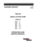
The Gardner Denver OPI-600 is a multipurpose pump for various applications such
as oil well servicing, water blasting,
industrial use, etc. The pump was designed
using
modern
analytical
engineering
methods and techniques for stress analysis
of structural components, gears, and journal
bearings. The gear drive was calculated in
accordance with the most recent standards,
procedures
and
computer
software
developed by American Gear Manufactures
Association. The OPI-600 has a proven
track record as a reliable, trouble-free pump.
The Issue of personnel safety is the most
important topic covered in this manual.
Therefore, in the beginning of this manual
the user is introduced to dangers inherent in
the operation of a high pressure pump. To
avoid accidents and injuries, all safety rules
listed in this section and also all other
applicable safety rules and regulations must
be carefully observed.
The sections on Pump Design, Description,
and Specifications, describe the pump
design, list the pump specifications, and
present drawings depicting the pump
external views and all essential crosssectional drawings.
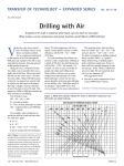
FIGURE 2-1 OPI-600 PUMP
Page 9
Section 3, "Pump Preparation, Operation,
and Maintenance," addresses the issues of
preparing the pump for operation after
shipping or storage, the lubrication system
design and specifications, the new pump
run-in procedures, and the periodic routine
maintenance schedule. The recommended
oils, viscosity data, and crankcase oil
temperature
requirements
are
also
presented in this section.
PUMP DESIGN
The OPI-600 is a horizontal single acting
600 horsepower triplex pump. It has a 6
stroke and various plunger sizes from 2.75
diameter through 5 diameter. The weight of
this pump will vary slightly due to the various
accessories, but will not exceed 5,000
pounds. Materials used in the power end
have been selected to provide long life, and
meet the rigorous demands required for well
servicing applications. All sizes of plunger
fluid ends are interchangeable on the power
end.
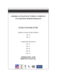
POWER END
The power end is available with 4.68:1 ratio
gearbox only. This is a dry sump pump
designed for pressure lubrication fed
through
various
hoses
and
drilled
passageways to the main bearings, rod
bearings, crossheads, etc. Because of the
various drive arrangements for powering
these pumps, the lubrication pump itself is
not built-in. It must be sized and mounted to
suit each particular application.
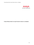
NOTICE
The direction of rotation must be
such that the top side of the
crankshaft is moving toward the fluid
end (clockwise in the figure below).
FIGURE 2-2 OPI-600 POWER END CROSS SECTION
Page 10
CROSSHEAD ASSEMBLY
The crosshead assembly features a wrist
pin which is made of heat treated, high
strength alloy steel, then nitrided and ground
for an optimum bearing surface. The wrist
pin bushing has chevron style oil grooves to
maintain lubrication pressure throughout the
connecting rod oscillation. Oil is fed under
pressure to the wrist pin bushing through a
drilled passageway in the connecting rod to
further extend the durability of this
assembly.
a 2 NPT drain in the cradle drains any
excess packing lube. User plumbing will
direct drain oil flow back into the lube sump.
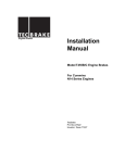
FLUID END
The conventional valve over valve
configuration offers field proven valve and
spring performance. Improvements in the
fluid end life come from:
1.
New sophisticated methods of
metallurgical control which enable us to
obtain steel with very consistent
chemical components and mechanical
properties. This results in extended
fluid end life.
2.
Internal edges and corners are hand
radiused, blended and polished for
improved resistance to fatigue
cracking.
3.
Extreme pressure autofrettage is
available for longer fluid end life and
resistance to cracking at the bore
intersection areas.
GEARBOX
The gearbox is a parallel shaft style unit
consisting of a bull gear and pinion. The
gears are constructed from alloy steel then
heat treated and ground for extended
service life.
The gearbox may be
repositioned
radially
at
45
degree
increments for flexible installation.
In
addition, the pinion shaft is reversible for
under drive mounting configurations.
CRANKSHAFT
The crankshaft is made of high strength
alloy steel that has been precision machined
and heat treated for fatigue resistance and
long wear.
It has been drilled with
lubrication passageways to provide oil for all
the connecting rod journal bearings as well
as the crosshead assembly.
POWER END INTERNAL LUBE SYSTEM
There is a single inlet for the lube oil,
coming from the lube oil pump.
After
entering the inlet, the lube oil flow is divided
into two lines:
1.
Through external hoses and rotating
unions the lubrication oil enters the
crankshaft where it is distributed to the
connecting rod journal bearings and the
and wrist pin bushings.
2.
Through the lubrication manifold, oil is
distributed to the gearbox, main
bearings, and the outside of the
crosshead.
There are two drain holes on the bottom of
the power frame. A 3 NPT drain below the
crankcase drains the power end lube, while
Page 11
FIGURE 2-3 FLUID END
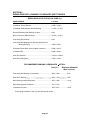
GENERAL SPECIFICATIONS
This section presents the pump basic specifications (U.S. & Metric). The first set of specifications
deals with the pump's power, rod load, plunger stroke, and overall dimensions. Two other tables
present allowable pressures and flows for various plunger sizes and pump RPM s along with data
on power requirements.
OPI-600 PUMP SPECIFICATIONS (U.S. SYSTEMS)
Rated Hydraulic Horsepower
600 hp
Stroke Length
6.0 Inches
Maximum Rod Load
100,000 Pounds
Gear Ratio
4.68:1
Weight (system dry)
5,000 Pounds
OPI-600 PERFORMANCE RATING
Plunger Gallons
Size
Per
(Inches)
Rev.
2.75
0.463
3.0
0.551
3.5
0.749
4.0
0.979
4.5
1.239
5.0
1.529
Brake
Horsepower*
100 RPM
200 RPM
U.S.
300 RPM
450 RPM
GPM
PSI
GPM
PSI
GPM
PSI
GPM
PSI
46
55
75
98
124
153
16845
14154
10399
7962
6291
5096
93
110
150
196
248
306
10004
8406
6176
4729
3736
3026
139
165
225
294
372
459
6669
5604
4117
3152
2491
2071
208
248
337
440
557
688
4446
3736
2745
2102
1660
1345
500
600
600
* Based on 90% Mechanical Efficiency and 100% Volumetric Efficiency.
Page 12
600
SECTION 3
PREPARATION, OPERATION AND MAINTENANCE
6.
Coat the gear reducer input shaft and
all exposed bare metal with a heavy
rust preventive.
7.
Plug drain holes at the bottom of the
pump frame, at the rear of the pump,
and the gear reducer drain.
8.
Plug the lube inlet in the lube manifold.
9.
Store the pump inside in a warm dry
place.
DANGER
Read and understand clearly all
safety rules and precautions before
attempting to operate the pump.
This section deals with pump preparation
after shipping and storage of the pump, user
built
lubrication
system
and
its
specifications, pump break in procedures,
recommended oils, allowable crankcase
operating
temperatures,
viscosity
conversion tables, and routine maintenance
schedule.
PREPARATION AFTER SHIPPING AND
STORAGE
All pumps are shipped dry and therefore
must be flushed with light weight oil before
operating. The flushing must be performed
regardless of method or duration of the
shipment or type of container the pump was
shipped in.
Pumps are not prepared for storage and
should be put in service as soon as
possible.
10. If the pump is shipped ocean cargo, it
must be crated in a water-tight container placed below the deck to prevent
rusting and salt water contamination.
PUMP MOUNTING INSTRUCTIONS
Because of the lightweight, low stiffness
nature of these pumps, it is easy to twist or
distort the frame during installations.
Therefore, it is necessary to follow this
procedure to shim the feet of these pumps.
This requires (4) grade 8, 13/16 diameter
cap screws of the appropriate length,
lockwashers, nuts, if required, and shims if
required.
1.
Set the pump in its location.
If for any reason the pump has to be put into
storage after prior use, the following
procedure should be followed:
2.
Using a feeler gauge, check under the
feet at all four boltdown locations.
1.
Clean and flush the fluid end with a rust
preventative.
3.
2.
Plug all
openings.
Select the proper number and
thickness of shims to fill the gap under
the high foot. Note it is better to use
shims up to .005 too thick than to
leave any gap under the foot.
3.
Drain oil from the power end and the
gear reduction unit.
4.
With shims in place, install bolts in all
four locations.
4.
Flush the power end with a rust
preventative (before flushing make sure
that the rust preventative will not clog
the oil passages).
CHARGING PUMP REQUIREMENT
5.
discharge
and
suction
Remove the breather and either plug or
tape the opening.
A centrifugal pump will be required to prime
the fluid end suction. The centrifugal pump
should be sized to generate a minimum of
50 PSI at maximum flow.
Increased
pressure is required for pumping higher
volumes, heavy sand concentrations, and
Page 13
other special fluids and propping agents. To
reduce shock and cavitation, which can
cause severe damage, a suction dampener
should be used.
3.
The suction strainer should be sized for
oil flow three (3) times larger than the
actual flow passing through the
strainer.
POWER END LUBRICATION SYSTEM
4.
The suction pipe should be kept as
short as possible and free of bends.
5.
Warning devices to monitor lube oil
pressure and temperatures are highly
recommended. The triplex pump
operates at very high rod loads and
pressures, and malfunction of the lube
system may result in serious damage
occurring in a very short time.
Therefore, early warning devices are
essential to successful operation and
should be set according to the following
operating limits:
Due to variety of applications and drive
arrangements, the power end lubrication
pump and applicable auxiliary hydraulic
equipment are not furnished with the triplex
pump.
Therefore, the pump lubrication
system is designed and built by individual
customers for each particular application.
The lubrication system is very critical to the
triplex pump performance and therefore
should be professionally designed in
accordance
with
sound
engineering
practices developed for similar systems,
known otherwise as hydraulic power units or
HPU. The following discussion will reemphasize some of the good practices used
in designing similar systems in the past and
comment
on
the
system s
critical
components.
NOTICE
Maximum lube system pressure
should be set at 125 psi max.
(relief valve setting.)
Lube System Pump
Minimum lube oil operating
pressure is 40 psi (with hot oil).
A positive displacement pump must be
used. Gear type pumps have demonstrated
reliable performance for similar applications
in the past. The pump should have the
largest suction port available for the
selected pump size to minimize losses in the
suction piping.
Minimum lube pump flow is 15
gpm.
Lube system filter should have a
25 micron absolute rating with a
by-pass indicator.
Lube Pump Suction Piping Sizing and
Requirements
Maximum lube system vacuum at
lube pump inlet 8 Hg or 4 psi or
0.28 bar.
In the past, failure to meet these
requirements has lead to pump damage
because of restricted oil flow in the lube
pump inlet. Therefore, the following
guidelines, developed as a result of long
experience, should be adhered to closely.
1.
2.
The oil flow velocity through the suction
piping should not exceed 2 ft/sec or 0.6
m/sec.
At maximum operating speed the
vacuum reading at the lube pump inlet
must be no more than 8" hg or 4 psi or
0.28 bar.
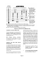
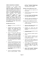
FIGURE 3-1 provides a typical lubrication
schematic for the pump.
FIGURE 3-2 Indicates API-GL5 oil grades
recommended for use in the pump power
end and the speed reducer lube system,
crankcase operating temperature ranges,
and minimum startup temperatures for each
listed grade of oil for various ambient
temperature ranges.
Page 14
FIGURE 3-1 LUBRICATION SCHEMATIC
Page 15
FIGURE 3-2 LUBRICANT RECOMMENDATIONS
PLUNGER / PACKING LUBRICATION
The fluid end plungers are lubricated from a
separate lubrication pump through the
stuffing box. The lubrication pump, hosing,
and check valve to the stuffing box are not
provided with the unit.
See
"Plunger
Packing
Lubrication
Recommendation Chart," page 19, for a list
of lubricants recommended for plunger
/packing lubrication.
STARTUP AND
PROCEDURES
NEW
PUMP
RUN-IN
A centrifugal charge pump will be required
to charge the fluid end suction manifold.
The charge pump should be sized according
to the volume to be pumped by the triplex
pump so that there is no less than 50 psi
charge when the triplex pump operates at its
maximum flow.
quality assurance procedure. However, the
new pump break-in period process may
continue for the first 80-100 hours of our
operation, and therefore it will be each
user s responsibility to perform all the tasks
related to this critical period. As all moving
parts of the pump go through a wearing-in
process, steel and bronze wear particles are
carried by the oil flow in the lubrication
system. The resulting contamination of the
lubrication system with the wear particles
and especially clogging of the strainer and
the oil filter can cause serious problems. To
assist the user, the following guidelines are
presented for the maintenance personnel to
follow during the critical startup and break-in
period:
1.
Fill the lube oil reservoir with the
recommended grade of oil.
See
FIGURE 3-2 above for Lubricant
Recommendations.
2.
Fill the plunger reservoir with proper
oil. See Plunger/Packing Lubrication
Recommendations on Page 19.
The first startup is performed at the factory
during the acceptance tests as a part of
Page 16
3.
Remove all inspection covers on the
back of the pump frame.
4.
Start the engine at the lowest
possible RPM and triplex pump at
zero (0) pressure. Make sure that all
roller bearings, crossheads, wrist pin
joints, and crankshaft bearings have
proper lubrication.
5.
6.
Increase the engine RPM to
maximum operating speed and check
whether the vacuum reading at the
lube pump suction inlet is less the 8
Hg or 4 psi or 0.28 bar.
Check whether the lube system
pressure reading is at least 100 psi or
7.0 bar. Temporary pressure gages
should be also checked at this time to
make sure that all components of the
lube system are working properly.
7.
Check to see that oil flow back to the
reservoir is normal. (There should be
no accumulation in the power end.)
8.
Start the plunger lube system and
check whether it is adjusted properly.
9.
Replace the rear covers and run at
low speed to work out any trapped
air in the fluid end with the charge
pump operating.
10.
Run the pump at 80-90 strokes per
minute and 20% of its maximum
pressure rating for 30 minutes.
11.
During this time observe the suction
vacuum gage reading, oil pressure
and temperature and check for leaks.
12.
Run the pump at 80-90 strokes per
minute at the following loads:
40% of full rated load
60% of full rated load
80% of full rated load
100% of full rated load
13.
14.
If the triplex pump is equipped with a
transmission, run the pump for 30
minutes in each gear in the higher
gear ranges pulling full horsepower in
each gear.
Observe the oil
pressures, temperatures, and lube oil
suction vacuum closely.
15.
Shut the pump down and let it cool
thoroughly before starting normal
operation of the pump.
16.
During the shutdown, change the oil
filter elements and clean the suction
strainer.
17.
Change the lube oil and clean the
reservoir to get rid of metal particles
and any other wear products now
present in lube oil system.
18.
Change filter elements and clean the
strainer every 10-15 hours until it
becomes apparent that the wear-in
process is finished.
19.
Change the lube oil again, replace
the filter elements, and clean the
strainer after 80-100 hours of pump
operation.
20.
Follow the routine maintenance
schedule described in the next
chapter after completion of the wearin period.
30 min
30 min
30 min
30 min
During the operation, observe the oil
pressure and temperature, and inlet
suction vacuum gage reading, and
entire system for proper operation.
Page 17
packing nut is tightened sufficiently into
fluid end.
Recheck tightness after
extended continuous operation.
PERIODIC MAINTENACE SCHEDULE
Performance of the periodic routine
maintenance tasks, described in this
section, will ensure long, economical, and
trouble free operation of this pump. It is
highly recommended that the customer set
up a maintenance program during the run-in
period.
The periodic maintenance data
should be recorded and kept with other
pump
documents.
The
following
recommendations should serve as a
guideline
for
establishing
a
good
maintenance
program.
The
periodic
maintenance schedule is divided into daily,
monthly, and quarterly tasks to be
performed by the user after the pump has
gone through 100 hours of wear-in. For the
tasks performed during the wear-in period,
see "Startup and New Pump Run-In
Procedure," page 16.
Monthly (100 hour) Maintenance Tasks
1.
Clean the strainer and replace the oil
filter element.
2.
Check the entire lube system for leaks
and eliminate them.
3.
Check all fluid end expendables such
as valves, packings, and valve seats
and replace them as necessary.
4.
Check the power end extension rod
seals and replace them as necessary.
Quarterly (300 hour) Maintenance Tasks
1.
Change the lube oil and clean the oil
reservoir thoroughly.
Daily Maintenance Tasks
1.
Check the oil level in the lube oil
reservoir.
2.
Clean the lube system strainer and
replace the oil filter elements.
2.
Periodically monitor lube oil operating
pressure
and
temperature.
The
maximum oil operating temperature
depends on a particular grade of oil
used in the pump lube system.
3.
Re-tighten the critical bolt joints
following torque specifications given in
Section 6.
4.
Add grease to any exposed bare metal
to prevent corrosion.
5.
Clean or replace the breather cap filter
element.
6.
Check all pressure, temperature, and
vacuum gages for proper operation
and replace as necessary.
7.
Check all lube system warning and
alarm devices for proper operation and
replace if found defective.
8.
Check supply of on hand expendables
such as packings, valves and seats,
maintenance items such as seals.
Order to replenish supplies as
necessary.
9.
Check bearings and wear surfaces for
failure until operating experience
justifies longer inspection intervals.
3.
4.
5.
Check the lube pump suction inlet
vacuum.
A vacuum gage reading
higher than 8" Hg or 4 psi or 0.28 bar
indicates that the suction strainer
and/or oil filter element are clogged.
The strainer must be cleaned, and the
oil filter element replaced as necessary
as soon as the pump can be shut down
for a short period of time to perform
these tasks.
Listen for any abnormal noise or rough
operation, which may indicate the need
for fluid end maintenance such as
changing valves or valve seats. Due to
very high pressures in the triplex pump
fluid end, worn valves and seats should
be changed as soon as possible to
prevent washing them out with the
pumped fluid.
Check the plunger/packing lubrication
pump for proper operation. Ensure
Page 18
PLUNGER PACKING
LUBRICATION RECOMMENDATION CHART
Source
Amoco
Arco
Chevron Oil U.S.A.
Conoco
Gulf Oil (Chevron)
Exxon
Mobil Oil Co.
Pacer Oil
Phillips Petroleum
Shell Oil Co.
Sun Oil Co.
Texaco Oil Co.
Union Oil of Ca.
ROCK DRILL LUBRICANTS - NORMAL CONDITIONS
Type
Pour Point Maximum
Amoco Rock Drill Oil - Light
Amoco Rock Drill Oil - Medium
Air Drill #147
Arco Trueslide #150
Vistac #68X
Vistac #100X
Vistac #150X
EP Rockdrill #49, #17, #78
Rockdrill #100
Rockdrill #32
Arox EP #46
Arox #150
Almo #525
Almo #527
Almo #529
Almo #532
Rockdrill #150
Rockdrill #600
EP #500 (Summer) or EP #300 (Winter)
Torcula Oil #32
Torcula Oil #100
Torcula Oil #150
Torcula Oil #320
Rockdrill 500 (Light)
Rockdrill 1000 (Heavy)
Rockdrill Oil XL
Rockdrill Oil XM
Rockdrill Oil XH
Marok 150
OPTIONAL PACKING LUBRICANTS
Category
Specification
Motor Oil
Motor Oil
10W30
5W40
Page 19
-20 F
0F
0F
15 F
10 F
5F
0F
5F
-30 F
-35 F
-20 F
-35 F
-20 F
-20 F
-10 F
0F
-10 F
0F
-10 F
-50 F
-20 F
-15 F
-10 F
5F
5F
-40 F
0F
-10 F
------
SECTION 4
SERVICE PROCEDURES
This section describes various assembly
and disassembly procedures necessary for
pump servicing or parts replacement. The
General Requirements and Safety Rules
section is a reminder for the maintenance
personnel of the critical importance of safety
rules and precautions while working on the
pump.
Notes on dangers and notices
specifically related to service procedures are
repeated and placed in this section also.
FLUID END SERVICE
This discussion starts with the description of
steps necessary for removal and installation
of the fluid end assembly and proceeds to
the removal and replacement of expendable
parts such as valves, valve seats, and
packing.
Fluid End Removal
The pump consists of three major modules:
(1) the fluid end, (2) the power end, and (3)
the gear reduction unit. The description of
service procedures follows the modular
concept. Due to many expendable parts,
fluid end servicing is rather common in the
field and is therefore presented in the very
beginning followed by power end and gear
reduction unit servicing procedures.
1.
Disconnect suction and discharge lines,
plunger oiler lines, and also any
accessories such as stroke counters,
pressure gages, etc. from the fluid end.
2.
Open the hinged cradle cover on the
top of the crosshead housing, if
equipped, and disconnect the plungers
from the extension rods by removing
the extension rod clamps.
3.
Slide the plungers into the fluid end as
far as possible.
4.
Connect a hoist to the fluid end and
tighten the lines until they are snug
only. Make sure that hoisting slings are
not too tight, because that may cause
a strain on the fluid end and cause
injury or damage when removing from
the pump frame.
5.
Remove the twelve (12) 1-1/2 socket
head capscrews from the fluid end
using a hydraulic torque wrench with a
modified 1-1/2 12 point socket (OD
ground to 2.19 max) for a 1 drive or a
hand tool combination of a 4X1 torque
multiplier, a 3/4 drive torque wrench, a
1 drive extension, and a modified 11/2 12 point socket (OD ground to
2.19 max) for a 1 drive.
6.
Pull the fluid end assembly horizontally
forward, straight away from the power
end until it is completely clear of the
1/4 dowel pins.
7.
Move the fluid end to the service area
for changing valves or other service.
General Requirements and Safety Rules
DANGER
Before any attempt to work on pumps
is made, all safety rules and
precautions described in this manual
must be read and clearly understood.
DANGER
Only qualified and specially trained
personnel should be allowed to work
on this pump.
DANGER
Proper capacity hoist and lifting
devices should be used while
working on pump.
Page 20
debris or surface imperfections such as
corrosion or raised metal. Reassemble
the unit and recheck the clearance.
NOTICE
The
procedure
for
fluid
end
installation is presented separately
due to the special and critical nature
of the connection between the power
end and the fluid end.
Fluid End Installation
1. Clean the surfaces between the mating
faces of the power end counter bores,
stuffing boxes, and fluid end, removing
any debris or surface imperfections
such as corrosion or raised metal.
Make sure the o-rings and gaskets are
in place.
8. Tighten the fasteners to 80-100 ft-lbs.
using a hydraulic torque wrench with a
modified 1-1/2 12 point socket (OD
ground to 2.19 max) for a 1 drive or a
hand tool combination of a 4X1 torque
multiplier, a 3/4 drive torque wrench, a
1 drive extension, and a modified 1-1/2
12 point socket (OD ground to 2.19
max) for a 1 drive. Use the same
tightening sequence as step 6.
9. Check the clearance between the face
of fluid end and power frame. The
clearance of .003 - .030 should be
approximately the same at each of the
four corners.
2. Orient the stuffing boxes so that the 1/4
dowel pin holes are on top.
10. Tighten the fasteners to 1250 ft-lbs.
using the same sequence as step 6.
3. Lift the fluid end until the dowel pins
match the dowel pin holes in the stuffing
boxes and push the fluid end toward the
stuffing boxes.
11. Recheck the clearance between the
face of fluid end and power frame. The
clearance of .003 - .030 should be
approximately the same at each of the
four corners.
4. As seen in Figure 4-1, label the top row
of bolt holes on the frame starting from
the left corner to the right corner with the
following sequence of numbers: 9, 5, 1,
3, 7, 11.
5. As seen in Figure 4-1, label the bottom
row of bolt holes on the frame starting
from the left corner to the right corner
with the following sequence of numbers:
12, 8, 4, 2, 6, 10.
12. Repeat step 10, verifying that each
fastener is properly torqued to 1250 ftlbs.
13. Conduct a final check of the clearance
between the face of the fluid end and
power frame. The clearance of .003 .030 should be approximately the same
at each of the four corners.
6. Install the bolts hand tight using the
following sequence: 1, 2, 3, 4, 5, 6, 7, 8,
9, 10, 11, 12.
7. Check the clearance between the face
of the fluid end and the power frame.
The clearance range is between .003
and .030 . This clearance should be
approximately the same at all four
corners before proceeding.
If the
clearance is not the same at all four
corners, remove the fluid end and clean
the surfaces between the mating faces
of the power end counter bores, stuffing
boxes, and fluid end, removing any
Page 21
FIGURE 4-1 FLUID END TIGHTENING
SEQUENCE
12. Loosen the packing nut to allow for
installation of the plunger.
Plunger and Packing Replacement
This service procedure can be performed
with the fluid end in place on the pump, and
consists of the following steps:
1.
Remove the suction cover retainer nut
with the appropriate male hex wrench.
2.
Remove the suction cover with a
threaded slide hammer type puller.
3.
If equipped, open the hinged cover on
the top of the crosshead housing to get
access to the plunger/extension rod
area.
4.
Remove both capscrews holding the
plunger clamp, then remove the clamp.
5.
Loosen the packing nut to free the
plunger from packing pressure.
6.
Remove the plunger
suction cover opening.
13. Apply a light coat of grease or oil to the
clamp end of the plunger (approx. 2
in.). Insert the plunger through the
suction cover hole into the packing. It
may be necessary to bump the plunger
through the packing with a slide
hammer. Be sure to keep the plunger
level through installation.
14. Tighten the packing nut.
15. Inspect the clamp surfaces of the
plunger, and the extension rod for
cleanliness.
16. Install the plunger clamp and tighten
the clamp screws to the specified
torque.
17. Tighten the packing nut again.
through
the
7.
Remove the packing nut, packing, and
spacers.
8.
Inspect the plunger, the packing, the
rod wiper, the stuffing box bore, and
the packing nut for excessive wear,
nicks, burrs, or any other defects.
Replace
expendable
parts
as
necessary.
9.
Coat packing and stuffing box bore with
a light grease or oil.
10. Install the packing in the packing bore
with the packing lips toward the front of
the fluid end. See FIGURE 4-2.
18. Replace the o-ring and back-up rings
on the suction cover and apply grease
or o-ring lube.
19. Install the suction cover and tighten the
suction cover retainer nut.
20. Make sure that the plunger lube line is
in place before restarting the pump.
Valve and Seat Replacement
This procedure can be performed with the
fluid end on the pump. Before starting,
make sure that special tools required for this
procedure are available. For part number of
the tools see Parts Manual.
WARNING
Never try to remove or cut a valve
seat with a torch. Severe damage to
the fluid end may occur.
FIGURE 4-2 TYPICAL PACKING
ASSEMBLY
1.
11. Install and hand tighten the packing nut
to align the packing in the bore.
Page 22
Remove the discharge cover retainer
nut with the proper hex wrench.
2.
Remove the discharge cover with a
slide hammer type puller.
13. Reinstall the suction valve cover and
retainer nut.
3.
Remove the suction cover retainer nut
with the proper hex wrench.
14. Reinstall the discharge valve, spring,
cover, and retainer nut.
4.
Remove the suction cover with a slide
hammer type puller.
5.
Remove the suction valve spring
retainer. The suction valve spring and
valve can now be removed by hand.
15. Run the pump at 80% to 100% of the
maximum discharge pressure until the
seats pop into the fluid end tapered
holes. (Listen for 6 distinct loud pops )
POWER END SERVICE
DANGER
Before attempting to service the
power end of the pump, the following
safety precautions must be observed:
1. Shift the pump transmission into
the neutral gear.
2. Shut off the pump engine and
remove the key from the ignition
to prevent starting the engine
inadvertently.
FIGURE 4-3 VALVE CAGE SPRING
RETAINER
6.
7.
8.
9.
Extension Rod
1.
Remove any plunger / cradle-chamber
covers or guards.
2.
Remove the plunger and push it into
the fluid end.
Clean the valve seat deck thoroughly
using a non-petroleum based cleaner.
3.
Clean the replacement valve seat using
a non-petroleum based cleaner. Do
not apply any type of lubricant to the
seat or o-ring on the seat prior to
installation.
Unscrew the extension rod with a pipe
wrench on the knurled portion of the
rod (be careful not to damage the seal
surface). Remove the extension rod
through the top of the cradle section.
4.
Check the extension rod seal for wear.
Replace if necessary.
Snap the replacement valve seat into
the taper by hand to fit tightly.
5.
Before replacing the extension rod,
inspect the threads in the crosshead
and check for cracks on the extension
rod. Apply a light coat of anti-seize to
the extension rod threads.
6.
Install extension rod in crosshead.
Apply approximately 150 ft-lbs to
extension rod.
Remove the suction valve seat or
discharge valve seat with a seat puller
and a seat puller jack. These tools are
available from Gardner Denver.
10. Place the winged valve on the top of
the valve seat.
11. Bump the seat into the taper 2-3 times
with a heavy bar to make the fit tight.
12. Reinstall the valve spring and suction
valve spring retainer cage.
Page 23
7.
8.
Check to see that mating faces of
extension rod and plunger are free of
nicks or burrs. Any raised metal could
cause misalignment, resulting in poor
packing life.
1.
Remove the rear cover from the power
end.
2.
Remove the two locknuts from each
rod cap to be removed.
3.
Remove the rod cap, labeling each for
correct re-assembly.
5.
6.
7.
Using a rubber hammer or wooden
hammer handle, tap on one edge of the
bearing to work it around in the
connecting rod and out.
Use a
screwdriver to remove the bearing from
the crank journal.
Check the crankshaft journal surface
for wear or damage.
Polish if
necessary.
Clean the new bearings and connecting
rod
thoroughly
before
replacing
bearings. The grooved bearing half
goes in the cap and the non-grooved
half goes in the connecting rod.
Install the rod caps, making certain the
correct cap is assembled with the
correct rod.
8.
Tighten the locknuts on the rod caps to
450 ft-lbs.
9.
Before operating the pump, move the
connecting rod from side to side with a
large screwdriver to make sure the rod
is free on the crankshaft.
If new
bearings are installed, perform the
Run-In Procedure prior to field
operation.
3.
Remove the extension rods.
4.
Using strong internal snap ring pliers,
remove the snap rings from the from
the crosshead pin.
5.
Using a slide hammer or partially
threaded rod, remove the pin from the
crosshead.
6.
Remove
one
crosshead
and
connecting rod at a time. The middle
crosshead pin can not be removed until
the outer crosshead is removed.
7.
Remove the two locknuts from each
rod cap of the rod to be removed.
8.
Remove the rod cap, labeling each for
correct re-assembly.
9.
Remove the studs in the connecting
rod by locking two nuts onto the stud.
Remove the stud by loosening the
inner nut against the outer nut.
10. Remove the main bearing retainers
(1/2 -13 bolt, nut and washers)
opposite the crank throw.
11. Rotate the crankshaft to the back
stroke of the rod to be removed and
push the rod forward till it clears the
throw and lower it to the bottom of the
power end.
12. Rotate the crankshaft till the throw is on
top (90 degrees from the back position)
and remove the connecting rod out the
back of the power end, being careful
not to damage the crank throw.
13. Rotate the crosshead about the center
axis until it is free from the crosshead
guides. Remove the crosshead from
the power end through the side
inspection window.
14. Clean and inspect all bearings and
bearing surfaces.
Replace any
defective or worn parts.
Connecting Rod and Crosshead
1.
Remove the plunger clamps and push
the plungers into the fluid end.
Replace the plunger as detailed in the
previous section.
Connecting Rod Bearing
4.
2.
Remove the side and rear cover s from
the power end.
Page 24
15. Clean the oil port in the center of the
connecting rod.
16. When replacing the wrist pin bushing in
a connecting rod, make sure the oil
grooves are placed toward the rear
(crank end of the rod). Use a hydraulic
press to replace the wrist pin bushing,
as hammering will destroy the bushing.
If a hydraulic press is not available,
place the bushing in a freezer overnight
to allow the bushing to slip easily into
the connecting rod.
17. When re-installing the crossheads and
connecting rods, start with the center
assembly.
18. Re-install the crosshead, with one snap
ring in place, through the side
inspection window of the power end.
Rotate the crosshead about the center
axis, with the installed snap ring
towards the inside, till the crosshead is
in place in the crosshead guide shoes.
Push as far forward as possible.
26. Lift the front of the connecting rod and
slide the crosshead back until the wrist
pin bores align.
27. Install the wrist pin.
28. Install the snap ring into the groove in
the crosshead.
29. Re-install the main bearing retainers.
30. Repeat steps 16-27 until all connecting
rods and crossheads have been reinstalled.
31. Check crosshead guide clearances
prior to operation.
Crosshead Guides
1.
Remove the connecting rod and
crosshead of the guides to be serviced.
2.
Remove the lube system connections
to the crosshead guides.
3.
Remove the four (4) 1/2 -13 X 4 in.
capscrews from each crosshead guide.
Keep track of the crosshead guide shim
packs if the same guide and crosshead
is to be reused.
4.
Thoroughly clean and inspect guide for
pits, cracks, or scoring. Replace if
necessary.
5.
If replacing a crosshead or crosshead
guide(s) due to damage, both the upper
and lower crosshead guides must be
re-shimmed.
6.
Place the new guides in the power
frame, firmly seating the guides in the
frame before bolting.
7.
Install the four (4) crosshead guide
bolts. Do not use the rubber lined
washers until the shimming is
complete. Do not allow the bolt to pass
above the guide thread.
8.
Install the crosshead through the side
inspection window.
Rotate the
crosshead about the center axis (roll
upward and push down).
19. Install the non-grooved rod bearing into
the connecting rod.
20. With the crank throw at the top
position, feed the connecting rod into
the power end and place as far forward
as possible.
21. Rotate the crank throw to the back
stroke position.
Lift and pull the
connecting rod back until it is in place
on the crank throw.
22. Hand tighten the two studs into the
connecting rod. Apply Loctite 242 or
equivalent to the stud threads engaged
in the rod. Make sure the studs are
fully seated in the connecting rod.
23. Install the grooved rod bearing into the
cap.
24. Install the rod cap with bearing onto the
connecting rod.
25. Install and torque the rod cap locknuts
to 450 ft-lbs.
Page 25
9.
Install the extension rod.
pack would be calculated as follows:
0.032 - 0.012 = 0.020 in. shim pack.
10. With the extension rod seals out of the
seal bore in the frame, use an inside
micrometer to measure the distance
from the extension rod to the extension
rod seal bore at the top and bottom.
11. Subtract the bottom dimension from the
top dimension and divide by two to
obtain the shim pack required for the
lower guide (TOP-BOTTOM) / 2. For
example, if the distance from extension
rod to the extension rod seal bore is
0.895 in. on top and 0.855 in. on
bottom, the shim pack is calculated as
follows: 0.895-0.855 = 0.040, 0.040 / 2
= 0.020. The lower guide shim pack
would equal 0.020 in. to center the
extension rod in the seal bore.
12. Remove the
crosshead.
extension
rod
and
20. Remove the crosshead.
21. Remove the upper crosshead guide.
22. Install the calculated shim pack. Shim
packs are placed between crosshead
guide and each of the two frame
supports.
23. Install the upper crosshead guide.
24. Install the 1/2 -13 X 4 in. capscrews
into the upper guide. Do not allow
guide bolt to pass above thread.
25. Install the crosshead.
26. Slide crosshead from front to back,
checking for clearance of 0.009 to
0.015 in.
27. Shims make require minor adjustments
if areas of tight clearance occur.
13. Remove the lower crosshead guide.
14. Install the calculated shim pack. Shim
packs are placed between crosshead
guide and each of the two frame
supports.
15. Install the lower crosshead guide.
16. Install the 1/2 -13 X 4 in. capscrews
into the lower guide. Do not allow
guide bolt to pass above thread.
28. Once proper clearance is measured,
remove guide bolts and re-install with
ring of silicone and rubber washers
under the bolt heads. Torque guide
bolts to 75 ft-lbs.
29. Re-assemble
crossheads
connecting rods.
and
Gearbox
17. Install the crosshead with both guides
in place (lower guide has been
shimmed, upper guide has no shims
yet).
18. To shim the upper guide, measure the
clearance between the top of the
crosshead and upper guide. For best
results, use long feeler gauges and
average the clearance along the width
of the crosshead.
19. To obtain the upper guide shim pack,
subtract
the
average
operating
clearance (0.012 in.) from the
measured feeler gauge clearance. For
example, if the measured feeler gauge
clearance between the crosshead and
upper guide was 0.032 in., the shim
1.
Remove the companion flange from the
pinion shaft by removing the 1/2 -13 X
1 in. capscrew holding the pinion shaft
retainer to the end of the pinion. Pull
the companion flange off the pinion.
2.
Remove the outer bearing and seal
retainers, and pinion shims.
3.
Remove housing cover (hold the pinion
shaft in place while the cover is
removed).
4.
Remove the pinion shaft bearings and
the pinion shaft. Replace bearings or
pinion shaft if severely pitted, scored,
or worn (apply low heat to the inner
race to remove from the shaft).
Page 26
5.
Remove the crankshaft bearing snap
ring and bearing.
degrees F in an oven or oil bath to
install on the pinion shaft.
6.
Remove the gear snap ring.
7.
Remove the gear with the puller holes
provided. Inspect the gear for pitting,
cracks, and scoring and replace if
necessary.
21. While holding the pinion shaft in place,
install the gearbox housing cover. Use
silicone seal as gasket material.
8.
If case is being repositioned, hammer
out the 1-3/4 diameter freeze plugs.
22. Install the pinion bearing races into the
gearbox housing.
9.
Remove the eight (8) 1 -8 X 2 in.
socket head capscrews that retain the
gearbox housing to the pump frame.
23. Install the pinion bearing retainer (off
drive) and pinion bearing seal retainer
(drive) without shims.
Tighten the
retainers while moving the pinion back
and forth. When the pinion begins to
tighten and move with resistance, stop
tightening the retainers. Use the shims
in the shim pack to measure the
clearance between the housing and
retainer. Remove the retainers, add
the measured shim pack between the
retainer and the housing and re-install
the retainers. Recheck the movement
in the pinion. If the pinion does not
move, continue adding shims until the
pinion moves back and forth without
resistance.
The bull gear bearing
retainer needs no shims but needs
silicone seal as a gasket.
20. Install the pinion shaft into the pinion
bore of the gearbox housing.
10. Remove the gearbox from the power
frame.
11. Thoroughly clean and inspect all parts
prior to re-assembly.
12. Using a silicone seal, form a gasket
around the outside of the spherical
bearing adapter on the power end.
13. Install the gearbox housing onto the
power frame in the correct orientation
with eight (8) 1 -8 X 2 in. socket head
capscrews.
14. If previously removed, hammer in the
1-3/4 diameter freeze plugs with
silicone sealer.
15. If new bull gear is being installed, fit
key to shaft and gear. Key must fit with
0.000 to 0.001 in. clearance (slip fit).
Do not drive key in with excessive
force.
24. Install the companion flange.
25. Install the pinion shaft end retainer
using the 1/2 -13 X 1 in. capscrew to
hold the companion flange in place.
Crankshaft
1.
Remove the pump from the trailer and
move it to a service area with an
overhead lift, where the frame can
eventually be turned on its side.
2.
Remove the gearbox, connecting rods,
and crossheads.
3.
Remove the rotary lube union.
4.
Remove the crankshaft cover bolts
from the off drive side (eight 1 -8 X 2 in.
capscrews).
16. Coat the crankshaft extension with
some light oil and install the gear with
the long hub side inward.
17. Install the gear snap ring with snap ring
pliers. Be sure snap ring is seated in
groove.
18. Install the crankshaft bearing and snap
ring. Be sure snap ring is seated in
groove.
19. Install the pinion bearings onto the
pinion shaft. Heat the bearings to 250
Page 27
5.
Remove the four (4) 1/2 -13 X 3-3/4
bolts from inside the frame, threaded
into the crankshaft cover.
6.
Remove the crankshaft cover.
7.
Place the power end on its side with
the crankshaft extension pointing
upwards. Lift the crankshaft upwards
using a lifting eye adapted to 4 -8
threads in the end of the crankshaft
extension. It may necessary to heat
the power end around the spherical
bearing retainer (less than 250 degrees
F oven or oil bath) to break the bearing
retainer away from the frame. Be
careful when pulling the crankshaft
roller bearings through the outer races,
as not to scratch the inner surfaces of
the races. Rotating the crankshaft
while pulling up aids removal.
8.
9.
Remove the bearing retainer, adapter,
and spherical bearing from the
crankshaft. It may be necessary to
heat the adapter and bearing to
remove.
Remove all the roller bearing retainers
(1/2 -13 X 3-3/4 capscrews, nuts and
washers) from the crankshaft.
10. Remove the bearings from the
crankshaft. It may be necessary to
apply low heat to remove the bearings
from the crankshaft.
11. Remove all the roller bearing retainers
in the power end.
12. Remove the outer races of the bearings
in the frame by tapping them out with a
soft metal (brass) bar.
13. Thoroughly clean and inspect all parts
for cracks, pits, or scoring and replace
if necessary prior to re-assembly.
Frame bores should be clean and
smooth, free of nicks and raised metal.
14. Label the three (3) straight roller
bearings and outer races as match sets
for proper re-assembly.
15. For easiest assembly, place the outer
bearing races in the freezer for at least
8 hours to allow the bearing races to
shrink.
16. On the inner side of the two inner main
bearing rings of the frame (closest to
the centerline), install three (3) of 1/2 13 X 3-3/4 capscrews with main
bearing retainer washers between the
frame and bolt head. On the opposite
side of the frame, install a nut on the
capscrew. The washers will act as a
stop for the outer bearing races during
re-assembly and center the outer
bearing race in the bore of the frame.
17. One at a time, remove the outer
bearing races from the freezer and
install in the two inner bearing bores of
the frame by passing the race through
the outer frame bores.
The outer
bearing races should shoulder against
the installed washer. Keep the races
as level as possible during the
assembly process.
18. On the inner side of the off drive
outside main bearing ring of the frame,
install three (3) 1/2 -13 X 3-3/4
capscrews with main bearing retainer
washers between the frame and bolt
head. On the opposite side of the
frame, install a nut on the capscrew.
The washers will again act as a stop for
the final main bearing outer race.
19. Remove the final outer bearing race
from the freezer and install in the off
drive main bearing bore of the frame.
Keep the race as level as possible
during the assembly process.
20. The outboard bearing bore on the input
side of the frame should be left open.
21. Remove the nuts on the main bearing
retainer bolts and install retainer
washers and locknuts (the off drive
outside main bearing retainers in the
frame can not be installed until the
crankshaft cover is installed).
22. On the inner side of the two inner
cheeks of the crankshaft (closest to the
centerline), install three (3) of 1/2 -13 X
3-3/4 capscrews with main bearing
retainer
washers
between
the
Page 28
crankshaft cheek and bolt head. On
the opposite side of the crankshaft,
install a nut on the capscrew. The
washers will act as a stop for the main
bearings during re-assembly and
center the bearing on the crankshaft.
31. Re-install the crankshaft cover using
silicone seal as a gasket.
23. One at a time, heat the straight roller
bearings (less than 250 degrees F
oven or oil bath) and install on the two
inner cheeks of the crankshaft by
passing the bearing over the outer
crankshaft cheeks. The roller bearings
should shoulder against the installed
washer. Keep the bearings as level as
possible during the assembly process.
33. Install the four (4) 1/2 -13 X 3-3/4
capscrews and main bearing retainer
washers on the inside of the frame
through to the crankshaft cover.
24. On the inner side of the off drive
outside crankshaft cheek, install three
(3) 1/2 -13 X 3-3/4 capscrews with
main bearing retainer washers between
the crankshaft and bolt head. On the
opposite side of the crankshaft cheek,
install a nut on the capscrew. The
washers will again act as a stop for the
final main roller bearing.
36. If new bearings were installed, repeat
the new pump run-in procedure.
25. Heat the final main roller bearing and
install on the off drive main bearing
cheek of the crankshaft. Keep the race
as level as possible during the
assembly process.
32. Install the eight (8) 1 -8 x 2 in. socket
head capscrews holding the crankshaft
cover to the outside of the frame.
34. Re-install the rotary union, crossheads,
connecting rods, and gearbox.
35. Remount pump on skid or trailer.
WARNING
Do not drive against rollers or bearing
cage. Drive only against the bearing
race, as severe damage to the bearings
could occur.
26. The outboard bearing cheek on the
input side of the crankshaft should be
left open.
WARNING
27. Heat and install the spherical bearing
onto the drive side crankshaft cheek.
28. Install the spherical bearing retainer
onto the crankshaft.
29. Heat and install spherical bearing
adapter onto the spherical bearing.
30. Lift the crankshaft with a lifting eye
screwed into the end of the crankshaft
and lower into the power frame (the
power frame should still be on its side
with the input end up). Rotating the
crankshaft while lowering will aid the
installation. Tap the spherical bearing
adapter to complete the installation.
When reassembling the crankshaft
assembly, make sure to follow these
steps:
1. Freeze the outer bearing races or
pack in dry ice before assembling in
the frame.
2. Heat the roller bearings (straight and
spherical) before installing on
crankshaft. (250 F max. oven or oil
bath).
Failure to follow these directions may
result in serious damage to the pump.
Page 29
SECTION 5
TROUBLE-SHOOTING
PROBLEM
POSSIBLE CAUSE
SUGGESTED ACTION
Pump Overloads Driver.
1. Excessive pump speed
and/or discharge pressure.
1. Reduce pump speed and/or
pressure.
2. Blockage or closed
valve in discharge line.
2. Clean or open valve.
3. Incorrect plunger size.
3. Install the correct
plunger.
4. Improper bypass conditions.
4. See recommended system
layout, and correct error.
1. Pump not primed.
1. Prime pump.
2. Air or vapor pocket in
suction line.
2. Remove pocket from line.
3. Clogged suction line.
3. Clean out line.
4. Suction and/or discharge
valves propped open.
4. Remove the obstruction.
1. Worn or fluid cut valve.
1. Replace valve assembly.
2. Valve propped open.
2. Remove the obstruction.
3. Pump cavitating.
3. See Cavitation, Fluid Knock
or Hammer problem.
4. Fluid leakage.
4. Replace plungers/packing
and/or fluid end seals.
5. Erroneous gauge reading.
5. Recalibrate or replace
gauge(s).
1. Low head (NPSH).
1. Raise fluid supply level.
Install charging pump.
2. Insufficient charging pump
capacity.
2. Increase charging pump
speed or size.
3. Retarded fluid flow.
3. Remove restrictions
from suction line.
4. Erroneous gauge reading.
4. Recalibrate or replace
gauge(s).
Fluid Not Delivered.
Low Discharge Pressure.
Low Suction Pressure.
Page 30
PROBLEM
POSSIBLE CAUSE
SUGGESTED ACTION
Cavitation, Fluid Knock
or Hammer.
1. Improper suction system
layout.
1. See recommended system
layout in manual.
2. Low suction pressure.
2. See Low Suction Pressure
problem.
3. Suction stabilizer and
pulsation damper not used.
3. Install suction stabilizer
and pulsation damper.
4. Defective stabilizer or
damper.
4. Repair and recharge or
replace.
5. High fluid temperature or
viscosity.
5. Reduce pump speed.
6. High fluid vapor pressure.
6. Increase NPSH.
7. High acceleration head.
7. Increase supply line size.
Decrease supply line length.
8. Suction valve spring too stiff.
with low NPSH.
8. Use weaker spring.
9. Air/Gas in pumped fluid.
9. Allow more settling
time in supply tank.
Reduce pump speed.
10. Air entering suction line.
10. Repair suction line.
11. Air entering charging pump.
11. Tighten or replace shaft
packing or seal.
12. Air entering or charge gas
escaping from suction
stabilizer.
12. Repair and recharge
stabilizer
13. Multiple pumps operating in
phase.
13. Use a suction stabilizer
on each pump. Separate
lines may also be needed.
1. Line(s) not supported.
1. Install supports or
hangers.
2. Pump cavitating.
2. See Cavitation, Fluid Knock
or Hammer problem.
1. High ambient temperature.
1. Use an oil heat exchanger
with a circulating pump.
2. Improper type/grade oil used.
2. Use recommended oil.
3. Pump overloaded.
3. Reduce pump speed and/or
pressure.
4. Improper clearance in main
or rod bearings, crossheads
or bushings.
4. Check and adjust clearance.
Replace parts as required.
Suction or Discharge Line
Vibration.
High Crankcase Oil
Temperature.
Page 31
PROBLEM
POSSIBLE CAUSE
SUGGESTED ACTION
Knock In Power End.
1. Improper main bearing
clearance.
1. Check and adjust
clearances.
2. Incorrect pump rotation.
2. Reverse rotation.
3. Loose plunger coupling.
3. Check and tighten. Replace
if damaged.
4. Loose bearing housings/
covers.
4. Check and tighten.
Replace if damaged.
5. Worn crosshead pin.
5. Replace.
6. Worn crosshead pin bushing.
6. Replace.
7. Worn connecting rod to
journal bearing.
7. Replace.
8. Worn crankshaft.
8. Replace.
9. Worn crosshead.
9. Replace.
10. Worn main bearing.
10. Replace.
11. Valve noise transmitted to
power end.
11. See Excessive Valve
Noise problem.
12. Cavitation noise transmitted 12. See Cavitation, Fluid
to or causing shock loading in
Knock or Hammer problem.
power end.
Excessive Valve Noise.
Oil Leakage From
Stop Head.
1. Pump cavitation.
1. See Cavitation, Fluid Knock
or Hammer problem.
2. Seal on inserted valve
damaged or missing.
2. Replaced seal or valve.
3. Broken/weak valve spring(s)
3. Replace spring(s).
1. Worn, damaged or corroded.
extension rod.
1. Replace extension rod.
2. Worn oil stop head seal.
2. Replace seal.
3. Oil level too high.
3. Reduce oil level.
4. Excessive crosshead wear.
4. Replace crosshead.
5. Pressure in crankcase.
5. Clean or replace air breather.
6. Misalignment in front.
6. Loosen bolts and center.
crosshead guide cover.
Page 32
PROBLEM
POSSIBLE CAUSE
SUGGESTED ACTION
Oil Seal Leakage.
1. Worn sealing lip.
1. Replace seal.
2. Damaged sealing lip.
2. Replace seal.
3. Outside diameter not seated.
3. Clean and polish bore of
oil seal housing.
4. Shaft rough at seal lip.
4. Clean and polish shaft or
replace wear sleeve.
5. Pressure in crankcase.
5. Clean or replace air breather.
1. Short plunger/packing life.
1. See Short Plunger/Packing
Life problem.
2. Worn packing rings/metal.
2. Replace packing rings/metal.
3. Seal leaking at fluid
end.
3. Check seal, stuffing box
groove and sealing surface.
4. Corrosion due to wrong
stuffing box material
for pumped fluid.
4. Determine and install correct
stuffing box.
5. Stuffing box bore worn.
5. Replace stuffing box.
1. Worn, damaged or corroded
extension rod.
1. Replace extension rod.
2. Worn oil stop head seal.
2. Replace seal.
3. Stuffing box leakage.
3. See Stuffing Box Leakage
problem.
1. Abrasives in pumped fluid.
1. Filter pumped product.
Use severe duty valves
with insert.
2. Valve not sealing.
2. Broken valve spring - replace.
Worn valve guide - replace.
Worn valve/seat - replace.
3. Pump cavitating.
3. See Cavitation, Fluid Knock or
Hammer problem.
4. Corrosion.
4. Treat pumped fluid.
Use different materials
for valves/seats.
Install sacrificial anodes
in suction manifold.
Stuffing Box Leakage.
Pumped Fluid In
Crankcase.
Short Valve Life.
Page 33
PROBLEM
POSSIBLE CAUSE
SUGGESTED ACTION
Short Plunger/Packing Life. 1. Abrasives in pumped fluid.
1. Consult Gardner Denver
Customer Service for plunger /
packing recommendation.
Filter pumped fluid.
2. Excessive plunger/packing
friction.
2. Lubricate with rock drill oil.
Do not overtighten adjustable packing.
Use Gardner Denver plungers.
3. Metal parts or particles
wearing plunger.
3. Check stuffing box
alignment.
Check gland alignment.
Check plunger alignment.
Check packing for foreign
particles.
Replace lantern ring.
4. Wrong plunger/packing for
pumping conditions.
4. Consult Gardner Denver
Customer Service.
5. Wrong size packing.
5. Install correct size packing.
6. Improper packing installation.
6. Check installation procedure
and install correctly.
7. Excessive crosshead wear.
7. Replace crosshead.
8. Pump cavitating.
8. See Cavitation, Fluid Knock
or Hammer problem.
1. Pump overloaded.
1. Reduce pump speed and/or
pressure.
2. Start-up against closed
discharge valve.
2. Ensure valve is open
before starting.
3. Main bearing failure.
3. Repair or replace.
4. Plunger striking valve or
valve parts.
4. Check valve condition and
installation procedure.
5. Plunger striking fluid end.
5. Check plunger for proper
length.
6. Frozen liquid in fluid end.
6. Do not start pump when
pumped fluid is below freezing
temperature.
7. Lube oil pump failure.
7. Replace oil pump.
Catastrophic Failures:
Broken Shafts,
Bent Rods, etc.
Page 34
PROBLEM
POSSIBLE CAUSE
SUGGESTED ACTION
Catastrophic Failures:
Broken Shafts,
Bent Rods, etc.
(continued).
8. Low oil level in sump.
1. Check oil level frequently,
and add oil as required.
9. Contaminated oil in sump.
9. Check oil condition
frequently.
10. Cavitation shock loading.
10. See Cavitation, Fluid Knock
or Hammer problem.
1. Catastrophic failures.
1. See Catastrophic Failures
problem.
2. Improper nut torquing.
2. Check torque specifications
and torque to correct values.
3. Stud bending due to uneven
nut seating.
3. Check nut seat surface for
flatness. Rework or replace
as required.
4. Corrosive attack by pumped
fluid.
4. Treat fluid or use corrosion
resistant studs.
5. Studs damaged before
installation.
5. Check condition before
installation, and replace if
necessary.
6. Low strength studs.
6. Use Gardner Denver studs.
Stud Failures.
Page 35
SECTION 6
REBUILDING DATA, RUNNING CLEARANCES AND TORQUES
REBUILDING DATA FOR OPI-600 PUMP (in.)
PUMP STROKE
6 Inches
Crankshaft Throw Diameter................................................. 4.499 / 4.500
Crankshaft Shaft Diameter at Main Bearing ........................ 11.254 / 11.253
Distance Between Main Bearing Centers............................ 9.00
Bore in Frame for Main Bearings......................................... 15.249 / 15.251
Connecting Rod Centers ..................................................... 9.00
Connecting Rod Bearing Bore (Bearing Assembled in
Bearing Housing).................................................... 4.505 / 4.507
Crosshead Guide Bore (shim to obtain clearance) ............. 9.008 / 9.016
Crosshead OD .................................................................... 8.999 / 9.001
Wrist Pin Diameter .............................................................. 3.2475 / 3.2481
Wrist Pin Bushing Bore
.................................................... 3.254 / 3.255
RECOMMENDED RUNNING CLEARANCES
ACTUAL
New (in.)
Maximum Allowable
Wear Limit (in.)
Connecting Rod Bearing to Crankshaft ............................... .005 / .008 .................. 016
Wrist Pin to Bearing
..004 / .007
.020
Main Bearing Installed Clearance* ...................................... .005 / .008 .................. .016
Main Bearing Bench Clearance*.......................................... .011 /. 013
Crosshead to Guide*............................................................ .009 / 015 ................... .045
* Feeler gauge clearances .001 inch less than actual values.
Page 36
RECOMMENDED TORQUES FOR OPI-600 PUMP MAINTENANCE
DESCRIPTION
FASTENER
FOOT POUNDS
LUBRICATED
Crankshaft Cover to Frame. ................................ 1 -8
475
Gearbox to Frame................................................ 1 -8
475
Main Bearing Retainer Plate Washers ................ 1/2 -13
75
Plunger Clamp ..................................................... 1/2 -13
58
Crosshead Guide to Frame ................................. 1/2 -13
75
Connecting Rod (Cap to Rod) ............................. 1 -8
450
Suction Manifold to Fluid End .............................. 1/2 -13
75
Discharge Flange to Fluid End ............................ 3/4 -10
275
Fluid End to Frame .............................................. 1-1/2 - 12
1250
Page 37
PRODUCT WARRANTY
BE-13 R 02/2003, Copyright © 2003 Gardner Denver, Inc.
GENERAL PROVISIONS AND LIMITATIONS
Gardner Denver (the "Company") warrants to each original retail purchaser ("Purchaser") of
its new products, assemblies or parts from the Company or its authorized distributors that such
products are, at the time of delivery to the Purchaser, made with good material and workmanship.
No warranty is made with respect to:
1. Any product which has been repaired or altered in such a way, in the Company's
judgment, as to affect the product adversely.
2. Any product which has, in the Company's judgment, been subject to negligence,
accident, or improper storage, improper installation, operation or application. (Examples:
over-pressure, sand-outs, cavitation, corrosion, erosion or degradation).
3. Any product which has not been operated or maintained in accordance with the
recommendations of the Company.
4. Components or accessories manufactured, warranted and serviced by others.
5. Any reconditioned or prior owned product.
Claims for items described in (4) above should be submitted directly to the manufacturer.
WARRANTY PERIOD
The Company's obligation under this warranty is limited to repairing or, at its option, replacing,
during normal business hours at an authorized service facility of the Company, any part or
assembly which in the Company s judgment proved to have unsatisfactory material or
workmanship within the applicable Warranty Period as follows.
Except for the products or components listed below, and subject to the limitations and
restrictions set forth in the Disclaimer section set forth below, the Warranty Period for all
products is 1,250 hours of operation or three (3) months after start-up, not to exceed 120 days
after delivery to Purchaser, whichever occurs first. The exceptions are as follows:
1. Power end is warranted for twelve (12) months from date of start-up or eighteen (18)
months from date of delivery to the Purchaser, whichever occurs first.
2. Forged steel fluid ends are warranted for materials and workmanship for 6 months from
the date of installation or 18 months from the date of delivery to the purchaser, which
ever occurs first.
3. Repairs are warranted for 90 days from the date of delivery, for the workmanship and
materials of the new parts installed.
4. Weld repaired fluid ends and weld repaired components are not warranted.
5. Expendable fluid end parts, including, but not limited to, valves, valve parts, packing,
liners and pistons, are not covered by this warranty due to variable abrasive nature of
material pumped.
PRESERVATION ASSEMBLIES DESTINED FOR STORAGE
In order for warranty acceptance any pump assembly not immediately installed or destined to
be in storage or in transit for extended periods of time must be prepared for storage as defined in
the Company s Long Term Storage Procedure. This includes but is not limited to:
Drain and thoroughly clean inside power end crankcase.
Spray rust inhibiting oil on all bearing, machined and inside surfaces of the power end.
Induce clean gear oil into any circulating pump, filter, heat exchanger and piping.
Remove valves, seats and plungers from the fluid end. Thoroughly clean and dry these parts
and all internal surfaces. Coat all fluid end bores, valve covers and reusable expendable
parts with rust preventative.
Flush all water, and contaminants from pump, tanks, hoses and spray nozzles. Spray all
components with a rust inhibiting oil.
Page 38
Rotate pump every 30 days to insure bearings are oiled.
At the expense of the Purchaser, any product properly preserved must be inspected by an
authorized agent of the Company, prior to the Company, granting any extended warranty
beyond that stated in this warranty.
LABOR TRANSPORTATION AND INSPECTION
The Company will provide labor, by Company representative or authorized service personnel, for
repair or replacement of any product or part thereof which in the Company's judgment is proved not to
be as warranted. Labor shall be limited to the amount specified in the Company's labor rate schedule.
Labor costs in excess of the Company rate schedules caused by, but not limited to, location or
inaccessibility of the equipment, or labor provided by unauthorized service personnel is not provided for
by this warranty.
All costs of transportation of product or parts claimed not to be as warranted and, of repaired or
replacement parts to or from such service facility shall be borne by the Purchaser. The Company may
require the return of any part claimed not to be as warranted to one of its facilities as designated by the
Company, transportation prepaid by the Purchaser, to establish a claim under this warranty.
Replacement parts provided under the terms of this warranty are warranted for the remainder of the
Warranty Period of the product upon which installed to the same extent as if such parts were original
components.
The Company may request a root cause analysis be performed in-order to identify if a
request for warranty claim meets the requirements of this warranty.
DISCLAIMER
Except as to title, the foregoing warranty is the sole and exclusive warranty of the Company. The
Company hereby extends other manufactures warranty or guaranties, if any given to Company by such
manufacturer, but only to the extent the Company is able to enforce such warranty or guaranties. The
Company has not authorized any party to make any representation or warranty other than as expressly
set forthherein. SELLER HEREBY DISCLAIMS AND EXCLUDES ANY OTHER EXPRESS,
IMPLIED OR STATUTORY WARRANTIES, ARISING BY OPERATION OF LAW OR OTHERWISE,
INCLUDING, WITHOUT LIMITATION, ANY WARRANTIES OF MERCHANTABILITY OR
FITNESS FOR A PARTICULAR PURPOSE. COMPANY MAKES NO WARRANTIES OR
REPRESENTATIONS OF ANY KIND WHATSOEVER (EXPRESS, IMPLIED OR STATUTORY), OF
LAW OR OTHERWISE, ON ANY EQUIPMENT, COMPONENT PARTS OR ACCESSORIES SOLD
HEREUNDER WHICH, ARE NOT MANUFACTURED BY COMPANY.
NOTWITHSTANDING ANYTHING HEREIN TO THE CONTRARY, THE FOREGOING
WARRANTY SHALL BE THE SOLE AND EXCLUSIVE REMEDY AVAILABLE TO THE
PURCHASER. UNDER NO CIRCUMSTANCES, WHETHER IN CONTRACT, TORT OR
OTHERWISE, SHALL THE COMPANY S TOTAL LIABILITY ARISING IN CONNECTION WITH
ANY PURCHASE ORDER EXCEED THE AMOUNT OF ANY SALES OR OTHER PROCEEDS
RECEIVED PURSUANT THERETO. IN ADDITION, UNDER NO CIRCUMSTANCES, WHETHER
IN CONTRACT, TORT OR OTHERWISE, SHALL THE COMPANY BE LIABLE FOR
LIQUIDATED, SPECIAL, INDIRECT, INCIDENTAL, EXEMPLARY, OR CONSEQUENTIAL
DAMAGES, EXPENSES OR COSTS, INCLUDING, WITHOUT LIMITATION, LOST PROFITS OR
FACILITY DOWNTIME, HOWEVER CAUSED AND EVEN IF THE POTENTIAL OF SUCH
DAMAGES WAS DISCLOSED AND/OR KNOWN.
No statement, representation, agreement, or understanding, oral or written, made by any agent,
distributor, representative, or employee of the Company which is not contained in this Warranty will be
binding upon the Company unless made in writing and executed by an officer of the Company.
Page 39
This warranty shall not be effective as to any claim which is not presented within 30 days after
the date upon which the product is claimed not to have been as warranted. Any action for breach
of this warranty must be commenced within one year after the date upon which the cause of
action occurred.
Any adjustment made pursuant to this warranty shall not be construed as an admission by the
Company that any product was not as warranted.
WARRANTY REQUESTS
Products to be returned for warranty analysis shall be approved for return in writing by the
Company prior to shipment. All requests for product return shall be submitted by email.
Facsimile or letter to:
Warranty Department c/o
Gardner Denver Petroleum Pumps
4747 South 83rd East Avenue
Tulsa, Oklahoma 74145
Email:
[email protected]
Facsimile: (918) 664-6225
BE-13 R 02/2003, Copyright © 2003 Gardner Denver, Inc.
Page 40
For additional information contact your local representative or
Gardner Denver Inc.
4747 South 83rd East Avenue, Tulsa, OK 74145
PH: (918) 664-1151, (800) 637-8099
FAX: (918) 664-6225
www.gardnerdenver.com
Specifications subject to change without notice.
Copyright © 2001 Gardner Denver, Inc. Litho in U.S.A.