1
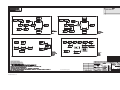
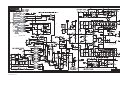
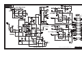
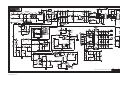
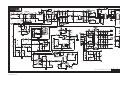
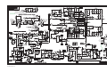
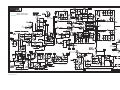
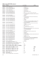
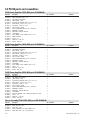
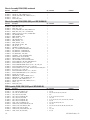
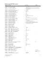
4.2 PL380 Amplifier
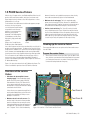
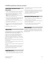
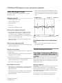
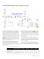
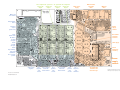
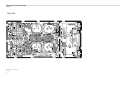
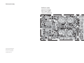
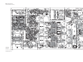
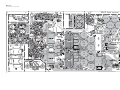
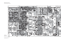
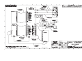
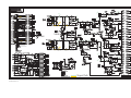
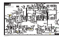
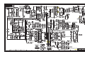
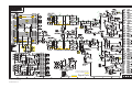
Main module circuit board assembly
Circuit board neighborhoods
See input
module drawing
Ch. 1 neg.
gate drive
Ch. 1 pos. Ch. 1 output
section
gate drive
Fan
Ch. 1 output
speed
filter network
Lower Speakon
Ch. 1 output
(Ch. 2) output
MOSFETs
Power supply
Binding
Upper Speakon control and gate drive TOP switch
post outputs
keep-alive supply
(Ch. 1 and 2) output
transformer
Top layer
AC rectifiers
and reservoir
capacitors
Loss of AC
detector
Inrush thermistors,
relays, and fuse
IGBT switches and
voltage spike filter
HF transformer
Power supply
section
Aux supply—
fan and audio
EMI filter
board
PL380 main circuit board, with
major circuit sections shown
58
Ch.2
gain pot
Ch. 1 temp
sensor
Ch.1
Ch. 1 & 2
gain pot temperature
signal amps
Ch. 2 pos.
gate drive
Ch. 2 output
filter network
Ch. 2 neg.
gate drive
Ch. 2 temp
sensor
Ch. 2 output
section
Ch. 2 output
MOSFETs
Class D gate
drive power
±25V supplies
HF power
rectifiers and
reservoir caps
QSC Audio Products, LLC