1
2045 LX Centrifugal Pump
2045 LX Centrifugal Pump
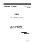
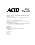
LX PUMP ASSEMBLY
1
2045 LX Centrifugal Pump
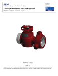
DISASSEMBLY OF LX PUMP
To disassemble pump, first remove nuts (12)
where indicated around entire perimeter of
pump housing.
2
2045 LX Centrifugal Pump
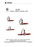
DISASSEMBLY OF LX PUMP
After (12) nuts are removed, entire rotating
assembly may be pulled out of volute as shown
above, using the push bolt holes as necessary.
Note: Due to cement build up between Volute and
pump housing it is sometimes difficult to remove
rotating assembly.
3
2045 LX Centrifugal Pump
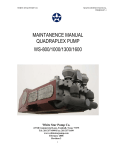
DISASSEMBLY OF LX PUMP
Remove Impeller retaining bolt.
4
2045 LX Centrifugal Pump
DISASSEMBLY OF LX PUMP
Use puller to remove impeller from shaft.
5
2045 LX Centrifugal Pump
DISASSEMBLY OF LX PUMP
Remove pipe nipple from stuffing box.
6
2045 LX Centrifugal Pump
DISASSEMBLY OF LX PUMP
After Impeller and pipe nipple are removed,
remove Impeller key from shaft with proper tool
being careful not to damage shaft.
Note: This key is specific finish tolerances. Check
for burrs, wear, nonconformance to shaft keyway.
Replace if needed.
7
2045 LX Centrifugal Pump
DISASSEMBLY OF LX PUMP
Remove back head.
8
2045 LX Centrifugal Pump
DISASSEMBLY OF LX PUMP
Remove two bolts from Packing Gland.
9
2045 LX Centrifugal Pump
DISASSEMBLY OF LX PUMP
Remove packing gland (follower). This will give access to
seals and lantern gland which may be removed from
stuffing box at this time.
Check all parts for wear.
Caution: Take care when removing seals to prevent
damage to seals and lantern gland.
10
2045 LX Centrifugal Pump
DISASSEMBLY OF LX PUMP
Before proceeding further with disassembly,
remove this grease fitting.
11
2045 LX Centrifugal Pump
DISASSEMBLY OF LX PUMP
Remove Slinger locking screw.
12
2045 LX Centrifugal Pump
DISASSEMBLY OF LX PUMP
Remove slinger.
13
2045 LX Centrifugal Pump
DISASSEMBLY OF LX PUMP
Remove these bolts (4).
Pick pump up and bump Impeller end of shaft
against a heavy block of wood. This will
remove shaft, bearings, and rear bearing
retainer as an assembly.
14
2045 LX Centrifugal Pump
DISASSEMBLY OF LX PUMP
Rear bearing retainer, shaft and both bearings should
slip out of the pump housing as an assembly. If the
front bearing becomes disengaged from shaft and
remains in the housing, it may be removed with the
proper tooling.
15
2045 LX Centrifugal Pump
DISASSEMBLY OF LX PUMP
Remove internal snap ring from rear
bearing retainer.
16
2045 LX Centrifugal Pump
DISASSEMBLY OF LX PUMP
Remove shaft and bearing(s) from rear bearing
retainer.
17
2045 LX Centrifugal Pump
DISASSEMBLY OF LX PUMP
Remove nut and lock from rear of shaft.
Bearing may be pressed off at this time.
18
2045 LX Centrifugal Pump
DISASSEMBLY OF LX PUMP
Remove rear seal.
19
2045 LX Centrifugal Pump
DISASSEMBLY OF LX PUMP
Check this area inside
shaft for wear.
Hydraulic
Motor Shaft
Severe wear may occur to pump shaft at a point where
splines of hydraulic motor contact shaft splines. Since it may not
be possible to see this wear from the outside of shaft, the internal
splines in shaft should be cleaned thoroughly with solvent and
then inspected under a strong light. If the wear in this area
exceeds .030, shaft should be discarded and no attempt to reuse
or repair should be made.
When splines become worn beyond the .030 limit, it becomes
difficult and sometimes impossible to disengage hydraulic motor
from pump shaft. If this occurs, the only solution is to cut motor
shaft or splined end of pump shaft off with a torch.
20
2045 LX Centrifugal Pump
ASSEMBLY OF LX PUMP
Reassembly of pump
should begin with the
replacement of seal in rear
bearing cover. Seal lip
should face to the rear of
housing away from rear
bearing. This prevents any
foreign material from
entering rear bearing
assembly.
21
2045 LX Centrifugal Pump
ASSEMBLY OF LX PUMP
Lock Nut
Rear Bearing
(Outboard Bearing)
Install rear bearing
and lock nut.
22
2045 LX Centrifugal Pump
ASSEMBLY OF LX PUMP
Insert the shaft and
rear bearing into
bearing cover.
23
2045 LX Centrifugal Pump
ASSEMBLY OF LX PUMP
Install front
(inboard) bearing
snap ring.
Install rear
(outboard)
bearing retaining
ring.
24
2045 LX Centrifugal Pump
ASSEMBLY OF LX PUMP
Install front
(inboard) bearing.
25
2045 LX Centrifugal Pump
ASSEMBLY OF LX PUMP
When shaft, bearings
and rear bearing cover
have been assembled,
stand this assembly
upright and install pump
housing.
26
2045 LX Centrifugal Pump
ASSEMBLY OF LX PUMP
Bolt rear bearing cover to pump
housing, but do not tighten bolts
(qty. 4, P/N 17519) at this time.
27
2045 LX Centrifugal Pump
ASSEMBLY OF LX PUMP
Install slinger but do
not tighten lock screw
at this time.
28
2045 LX Centrifugal Pump
ASSEMBLY OF LX PUMP
ANY PUMP THAT IS
PACKED WITH THREE
SEALS AND HAS THE
PACKING GLAND (follower)
WITH THE .625
DIMENSIONS INDICATED
BY DOTTED LINES (LEFT)
SHOULD BE MODIFIED TO
THE .125 DIMENSION AND
A 4TH SEAL ADDED AS
SHOWN ON PAGE 30.
29
2045 LX Centrifugal Pump
ASSEMBLY OF LX PUMP
Modify as
per 29781
Add one
seal.
Turn this seal around
to position shown.
Install seals (4) lantern gland and modified
packing gland into stuffing box in
backhead as indicated above.
Note: Lubricate O.D. of seals before installation and observe placement of number (3)
seal as the lip on this seal must face rear of
pump.
Item Req’d Part. No. Description
1
1
29781
Gland, Packing Modified
2
1
29782
Gland, Lantern
3
4
5826
Oil Seal, Solid Packing
30
2045 LX Centrifugal Pump
TYPICAL INSTALLATION OF
CENTRIFUGAL PUMP
PACKING
TUL29909
I. REMOVE ALL WORN PACKING RINGS FROM THE STUFFING BOX AND CLEAN SAME
THROUGHLY.
2. CHECK ALL BEARINGS PER THE MANUFACTURERS SPECIFICATIONS AND REPLACE
SAME IF NECESSARY. CHECK THE SHAFT AND REPLACE IF NECESSARY.
3. LUBRICATE THE 2 PRIMARY SEAL RINGS. INSTALL AND SEAT EACH SEAL RING
SEPARATELY, WITH ALL SEAL LIPS FACING TOWARD THE IMPELLER I STAGGERING THE
SPLITS AT THE 12 O'CLOCK AND THE 3 O'CLOCK POSITIONS SO THAT THERE IS NO
DIRECT LEAKAGE PATH ESTABLISHED.
4. LUBRICATE AND INSTALL THE 2 PIECE PLASTIC LANTERN RING.
5. LUBRICATE THE 2 SECONDARY SEAL RINGS. INSTALL AND SEAT EACH SEAL RING
SEPARATELY AND AGAIN STAGGERING THE SPLITS AS FOLLOWS:
(a) THE 1ST SECONDARY SEAL RING OF THIS SERIES MUST BE INSTALLED WITH
THE LIPS FACING AWAY FROM THE IMPELLER WITH SPLITS AT THE 6 O'CLOCK
POSITION. THE REVERSE POSITION OF THIS SEAL WILL PREVENT AIR FROM
BEING DRAWN THRU THE GLAND, AND THUS CAUSING THE LOSS OF PRIME.
(b) THE 2ND SECONDARY SEAL RING OF THIS SERIES MUST BE INSTALLED WITH THE
SEAL LIPS FACING THE IMPELLER, AND WITH THE SPLIT AT THE 9 O'CLOCK POSITION.
7. LUBRICATE, INSTALL AND SEAT THE SPLIT COMPRESSION PACKING RING WITH THE
SPLIT AT THE 12 O'CLOCK POSITION.
8. TO PROPERLY PRELOAD THIS COMBINATION SET, BOTTOM OUT THE FLAT SIDE OF THE
GLAND AGAINST THE FACE OF THE STUFFING BOX.
31
2045 LX Centrifugal Pump
ASSEMBLY OF LX PUMP
32
2045 LX Centrifugal Pump
ASSEMBLY OF LX PUMP
Install Packing in stuffing box area of
backhead as directed on page 31.
33
2045 LX Centrifugal Pump
ASSEMBLY OF LX PUMP
Install Packing Gland (Follower).
Install Packing gland bolts and
tighten to 60 Nm ± 10
A light coating of chassis lube
should be applied to the I.D. of
seal assembly at this time.
34
2045 LX Centrifugal Pump
ASSEMBLY OF LX PUMP
Cover the seal area of
the shaft with a light
coating of chassis lube
and install backhead
gasket and O-ring.
35
2045 LX Centrifugal Pump
ASSEMBLY OF LX PUMP
Install backhead assembly as shown above using guide pin for
proper alignment.
Caution: Be extremely careful when the #3 seal contacts shaft
as the lip on this seal points in the opposite direction of the
other three (3) seals. and serious damage can result to seal lip
or compression spring may become disengaged.
36
2045 LX Centrifugal Pump
ASSEMBLY OF LX PUMP
Install Impeller Key at this time.
Caution: This Key is special and a
standard Woodruff Key will not fit.
37
2045 LX Centrifugal Pump
ASSEMBLY OF LX PUMP
Install Impeller over shaft and
key, being very careful that key
does not become disengaged
from shaft.
38
2045 LX Centrifugal Pump
ASSEMBLY OF LX PUMP
Install impeller lock and bolt as
shown above and torque bolt to:
200 ± 15 lb. ft./280 ± 20 Nm
Install set screw as shown
above.
39
2045 LX Centrifugal Pump
ASSEMBLY OF LX PUMP
Entire rotating assembly may
now be inserted into volute.
Use mounting pedestals for
proper alignment.
Install housing nuts and torque
to 150 ± 20 lb. ft.l200 ± 25 Nm.
40
2045 LX Centrifugal Pump
ASSEMBLY OF LX PUMP
Screw Lube pipe with cap into backhead.
41
2045 LX Centrifugal Pump
ASSEMBLY OF LX PUMP
Install grease zerk (P/N 17516).
42
2045 LX Centrifugal Pump
IMPORTANT!!!
THIS PROCEDURE MUST BE
DONE FOR PUMP TO OPERATE
TO DESIGN.
For proper pump performance and long life, it is extremely
important that these adjustments be made with care as this
will assure the proper .030 clearance between the Impeller
and Volute.
Measure this distance
Turn all adjusting screws
counter clockwise until they are
flush with front face of rear
bearing retainer housing. Drive
bearing retainer forward until
Impeller contacts Volute. Turn
adjusting screws clockwise until
they contact pump housing.
Turn each adjusting screw 1/4
turn. Continue in this manner
until the initial distance
plus .030 is reached. Torque
retainer bolts to:
75 ± 10 lb. ft. / 100 ± 15 Nm
Re-measure distance between pump housing and rear bearing retainer as it
sometimes will change when retainer bolts are torqued.
Some early pumps will have two (2) adjusting screws and
two (2) retainer bolts while later models may have four (4)
adjusting screws and four (4) retainer bolts. This does not
affect adjusting procedure.
43
2045 LX Centrifugal Pump
ASSEMBLY OF LX PUMP
After pump has been installed and adjusted, adjust
slinger toward rear of pump until it contacts front
bearing and tighten lock screw.
44
2045 LX Centrifugal Pump
ASSEMBLY OF LX PUMP
After pump has been overhauled remove pipe plug in
bottom of pump housing and install grease fitting.
Remove pipe plug on side of housing. Pump NGL-1 or
NGL-2 chassis lube into housing until it starts to come out
of hole in side of housing where pipe plug was removed.
While grease is being pumped into housing, pump should
be turning as this will distribute lube to bearing and
prevent over filling.
45
2045 LX Centrifugal Pump
GARDNER DENVER DESIGN FEATURES GIVE
LONG LIFE & EASY MAINTENANCE.
The 2045 LX features two flow dividers resulting in
three throats positioned 120 degrees apart which
allows for a balance of thrust and forces and low
radial loads, shortened flow path, development of
full pressure at 1/3 revolution of impeller,
distribution of wear at three points, prevention of air entrapment and vapor lock,
reduction of shear and improvement of viscosity handling characteristics.
The GD 2045 LX drive system has a mounting adapter bracket predrilled to accept a
direct drive SAE “C” two, or four bolt hydraulic motor, and in conjunction with our
internal splined shaft eliminates down time due to misalignment.
Simplistic construction requires less assembly time and less spare parts inventory.
The impeller design is fully open and ideally suited for handling fluids containing
suspended solids. Impeller is available in an 8-vane pattern with a clockwise rotation.
The frame is available in two versions, economical cast iron and steel fabricated.
The GD 2045 LX offers two packing choices. Solid lip seals provide efficient service
with a minimum amount of attention. Split compression type packing is available for
more severe service conditions and can easily be replaced without dismantling the
pump.
Bearings provide maximum radial and thrust load capacity and are protected by a
water slinger.
46
2045 LX Centrifugal Pump
2045 LX Parts List
Ref
No. Name of Part
1
2
3
4
5
5A
6
6A
7
8
8A
9
10
11
12
13
GASKET DISCHARGE
SET SCREW
IMPELLER BOLT (Hex Design)
IMPELLER LOCK WITH ROLL
PIN
SPLIT LIP SEAL PACKING
RING
OIL SEAL SOLID PACKING
LANTERN GLAND, 2 PIECE
LANTERN GLAND, SOLID
SQUARE COMPRESSION PKG.
RING
PACKING FOLLOWER, 2 PIECE
PACKING FOLLOWER, SOLID
KEEPER
HEX BOLT (Pkg. Follower/
Backhead)
BEARING, INBOARD SINGLE
ROW
RETAINING RING, INBOARD
15
IMPELLER KEY
SHAFT, INTERNAL SPLINED
DRIVE
GREASE ZERK
16
RETAINING RING, OUTBOARD
17
BEARING, OUTBOARD Double
row
14
Qty.
Ref
No. Name of Part
Part No.
Qty.
Part No.
1
1
1
35193
28775
56102
18
19
20
BEARING LOCK NUT
OIL SEAL, OUTBOARD
GASKET SUCTION
1
1
1
61117
62961
35264
1
56103
21
VOLUTE
1
5620LR
1
5620LR-SP
2
1
1
17520
16125
24766
4
29795
21A*
3 or 4
1
1
5826
29797
29782
22
*
23
MODIFIED VOLUTE/NO PEDESTALS WITH EX DRAIN
1” PIPE PLUG
1/2” PIPE PLUG
GASKET, BACKHEAD
1
29796
24
IMPELLER, 8 VANE
1
74814
1
1
2
TUL29811
29781
29812
2
103284
25
26
27
28
O-RING BACKHEAD
BACKHEAD
LUBE PIPE WITH CAP
RETAINING SCREW,
SLINGER/SHAFT
1
1
1
1
17449
26081
14724
17522
1
TUL52480
29
SLINGER, 2 PIECE
1
29810
1
52481
1
1
26083
61088
30
31
32
1
12
TUL62960
17515
4
17519
1
17516
33
4
26029
1
26035
34
FRAME, CAST
HEX BOLT, FRAME/VOLUTE
HEX BOLT, BEARING
COVER/FRAME
THRUST AJUSTMENT
SCREW
BEARING COVER & MOTOR
BRACKET
1
26084
1
61116
* These items not shown on this assembly drawing.
47
2045 LX Centrifugal Pump
GARDNER DENVER PRODUCT WARRANTY
GENERAL PROVISIONS AND
LIMITATIONS
Gardner Denver (the "Company") warrants to each
original retail purchaser ("Purchaser") of its new
products, assemblies or parts from the Company or
its authorized distributors that such products are, at
the time of delivery to the Purchaser, made with good
material and workmanship. No warranty is made with
respect to:
1. Any product which has been repaired or altered
in such a way, in the Company's judgment, as to
affect the product adversely.
2. Any product which has, in the Company's
judgment, been subject to negligence, accident,
or improper storage, improper installation,
operation or application. (Examples: overpressure, sand-outs, cavitation, corrosion,
erosion or degradation).
3. Any product which has not been operated or
maintained in accordance with the
recommendations of the Company.
4. Components or accessories manufactured,
warranted and serviced by others.
Any reconditioned or prior owned product.
Claims for items described in (4) above should be
submitted directly to the manufacturer.
WARRANTY PERIOD
The Company's obligation under this warranty is
limited to repairing or, at its option, replacing, during
normal business hours at an authorized service
facility of the Company, any part or assembly which
in the Company’s judgment proved to have
unsatisfactory material or workmanship within the
applicable Warranty Period as follows.
Except for the products or components listed below,
and subject to the limitations and restrictions set
forth in the “Disclaimer” section set forth below, the
Warranty Period for all products is 1,250 hours of
operation or three (3) months after start-up, not to
exceed 120 days after delivery to Purchaser,
whichever occurs first. The exceptions are as
follows:
1. Power end is warranted for twelve (12) months
from date of start-up or eighteen (18) months
from date of delivery to the Purchaser, whichever
occurs first.
2. Forged steel fluid cylinders are warranted for
materials and workmanship for 6 months from
the date of installation or 18 months from the date
of delivery to the purchaser, which ever occurs first.
3. Repairs are warranted for 90 days from the date of
delivery, for the workmanship and materials of the
new parts installed.
4. Weld repaired fluid ends and weld repaired
components are not warranted.
5. Expendable fluid end parts, including, but not
limited to, valves, valve parts, packing, liners and
pistons, are not covered by this warranty due to
variable abrasive nature of material pumped.
PRESERVATION ASSEMBLIES DESTINED
FOR STORAGE
In order for warranty acceptance any pump assembly
not immediately installed or destined to be in storage
or in transit for extended periods of time must be
prepared for storage as defined in the Company’s Long
Term Storage Procedure. This includes but is not
limited to:
Drain and thoroughly clean inside power end crankcase.
Spray rust inhibiting oil on all bearing, machined and inside
surfaces of the power end.
Induce clean gear oil into any circulating pump, filter, heat
exchanger and piping.
Remove valves, seats and plungers from the fluid end.
Thoroughly clean and dry these parts and all internal
surfaces. Coat all cylinder bores, valve covers and
reusable expendable parts with rust preventative.
Flush all water, and contaminants from pump, tanks, hoses
and spray nozzles. Spray all components with a rust
inhibiting oil.
Rotate pump every 30 days to insure bearings are oiled.
At the expense of the Purchaser, any product properly
preserved must be inspected by an authorized agent of
the Company, prior to the Company, granting any
extended warranty beyond that stated in this warranty.
LABOR TRANSPORTATION AND INSPECTION
The Company will provide labor, by Company
representative or authorized service personnel, for
repair or replacement of any product or part thereof
which in the Company's judgment is proved not to be
as warranted.
Labor shall be limited to the amount specified in the
Company's labor rate schedule. Labor costs in excess
48
2045 LX Centrifugal Pump
GARDNER DENVER PRODUCT WARRANTY
of the Company rate schedules caused by, but not
limited to, location or inaccessibility of the equipment,
or labor provided by unauthorized service personnel
is not provided for by this warranty.
All costs of transportation of product or parts claimed
not to be as warranted and, of repaired or replacement
parts to or from such service facility shall be borne by
the Purchaser. The Company may require the return
of any part claimed not to be as warranted to one of
its facilities as designated by the Company,
transportation prepaid by the Purchaser, to establish
a claim under this warranty.
Replacement parts provided under the terms of this
warranty are warranted for the remainder of the
Warranty Period of the product upon which installed
to the same extent as if such parts were original
components.
The Company may request a root cause analysis be
performed in-order to identify if a request for warranty
claim meets the requirements of this warranty.
DISCLAIMER
Except as to title, the foregoing warranty is the sole
and exclusive warranty of the Company. The
Company hereby extends other manufactures’
warranty or guaranties, if any given to Company by
such manufacturer, but only to the extent the
Company is able to enforce such warranty or
guaranties. The Company has not authorized any
party to make any representation or warranty other
than as expressly set forth herein. SELLER HEREBY
DISCLAIMS AND EXCLUDES ANY OTHER EXPRESS,
IMPLIED OR STATUTORY WARRANTIES, ARISING BY
OPERATION OF LAW OR OTHERWISE, INCLUDING,
WITHOUT LIMITATION, ANY WARRANTIES OF
MERCHANTABILITY OR FITNESS FOR A
PARTICULAR PURPOSE. COMPANY MAKES NO
WARRANTIES OR REPRESENTATIONS OF ANY KIND
WHATSOEVER (EXPRESS, IMPLIED OR STATUTORY),
OF LAW OR OTHERWISE, ON ANY EQUIPMENT,
COMPONENT PARTS OR ACCESSORIES SOLD
HEREUNDER WHICH, ARE NOT MANUFACTURED BY
COMPANY.
NOTWITHSTANDING ANYTHING HEREIN TO THE
CONTRARY, THE FOREGOING WARRANTY SHALL
BE THE SOLE AND EXCLUSIVE REMEDY AVAILABLE
TO THE PURCHASER.
UNDER NO CIRCUMSTANCES, WHETHER IN
CONTRACT, TORT OR OTHERWISE, SHALL THE
COMPANY’S TOTAL LIABILITY ARISING IN
CONNECTION WITH ANY PURCHASE ORDER EXCEED
THE AMOUNT OF ANY SALES OR OTHER PROCEEDS
RECEIVED PURSUANT THERETO. IN ADDITION,
UNDER NO CIRCUMSTANCES, WHETHER IN
CONTRACT, TORT OR OTHERWISE, SHALL THE
COMPANY BE LIABLE FOR LIQUIDATED, SPECIAL,
INDIRECT, INCIDENTAL, EXEMPLARY, OR
CONSEQUENTIAL DAMAGES, EXPENSES OR COSTS,
INCLUDING, WITHOUT LIMITATION, LOST PROFITS OR
FACILITY DOWNTIME, HOWEVER CAUSED AND EVEN
IF THE POTENTIAL OF SUCH DAMAGES WAS
DISCLOSED AND/OR KNOWN.
No statement, representation, agreement, or
understanding, oral or written, made by any agent,
distributor, representative, or employee of the
Company which is not contained in this Warranty will
be binding upon the Company unless made in writing
and executed by an officer of the Company.
This warranty shall not be effective as to any claim
which is not presented within 30 days after the date
upon which the product is claimed not to have been as
warranted. Any action for breach of this warranty must
be commenced within one year after the date upon
which the cause of action occurred.
Any adjustment made pursuant to this warranty shall
not be construed as an admission by the Company that
any product was not as warranted.
WARRANTY REQUESTS
Products to be returned for warranty analysis shall be
approved for return in writing by the Company prior to
shipment. All requests for product return shall be submitted
by email. Facsimile or letter to:
Warranty Department c/o
Gardner Denver Petroleum Pumps
4747 South 83rd East Avenue
Tulsa, Oklahoma 74145
Email: [email protected]
Facsimile: (918) 664-6225
49
2045 LX Centrifugal Pump
GARDNER DENVER CENTRIFUGAL
PUMP APPLICATIONS
OILFIELD:
BLENDERS
MIXERS
CIRCULATION
SUPERCHARGING
DESANDING
TRANSFER
WATER FLOOD
DISPOSAL WELLS
WASHDOWN
OTHER GARDNER DENVER
PRODUCTS
HIGH PRESSURE TRIPLEX PUMPS FOR
ACIDIZING & FRACTURING
INDUSTRIAL:
SLURRY
FEATURES:
STEEL FABRICATED POWER FRAME
SOLID ONE-PIECE CONNECTING ROD
PRECISION GROUND CROSSHEADS
FORGED ALLOW STEEL CRANKSHAFT
HIGH-GRADE ALLOY STEEL GEARS
FOUR MAIN ROLLER BEARINGS
ORIFICED LUBRICATION SYSTEM
LIGHTWEIGHT ALUMINUM COVERS
INTERCHANGEABLE PARTS/STOCK
DESANDING
MIXING
TRANSFER
FOOD PROCESSING
CHEMICAL PROCESSING
IRRIGATION
MINING
OTHER GARDNER DENVER SERVICES
OVERHAUL AND/OR REWORK OF:
HIGH PRESSURE FLUID ENDS
FROM SOLID STEEL FORGINGS
Damaged or worn out frac power frames, fluid
ends, crossheads, or pressure headers,
mudpumps, centrifugal and slurry pumps and
5- to 8- stage centrifugal pumps, heat
exchanger tube bundle welding & refacing, etc.
Our specialty – Turn around work.
FEATURES:
UNIFORMITY OF ALL INTERNAL
SURFACES
ALL CORNERS CENEROUSLY
REDIUSED
ALL BORES HAND POLISHED
SHOT PEENED
AUTORETTAGE CAPABILITY
CUSTOM DESIGNS MADE ON
CONTRACT, BASED UPON RECEIPT OF
SPECIFICATIONS AND DRAWINGS
STANDARD REPLACEMENT CAN BE
PROVIDED FOR MOST PUMPS ON THE
MARKET
SPECIAL MATERIALS AND/OR
SPECIFIC MODIFICATIONS MAY BE
INCORPORATED INTO MOST
STANDARD DESIGNS.
MISCELLANEOUS MACHINING
MILLING & BORING
TURNING (TO 42” DIA.)
FABRICATION
WELDING
COMPLETE FIXTURE & TOOLING
DEPARTMENT
HYDROSTATIC & DESTRUCTIVE TEST
FACILITY
SHOT PEENING & STRESS RELIEVING
75,000 P.S.I. AUTOFRETTAGE FACILITY
50
2045 LX Centrifugal Pump
MAINTAIN PUMP RELIABILITY AND
PERFORMANCE WITH
GENUINE GARDNER DENVER
PARTS AND SUPPORT SERVICES
For the location of your local authorized Gardner Denver distributor, refer to
the yellow pages of your phone directory or contact:
Factory (Tulsa):
Service Center (Odessa):
Service Center (Ft.
Worth):
Geoquip
Chaparral
Gardner Denver Well
th
7533 Kathy Lane
2121 West 44 Street
Servicing Pumps
rd
Odessa, TX 79768
Ft. Worth, Texas
4747 South 83 East Ave.
76126
Tulsa, Oklahoma 74145
Phone: (918) 664-1151
(800) 637-8099
Phone: (432) 366-5433
(800) 368-1134
Phone: (817) 249-6400
(800) 824-0271
Fax:
Fax:
Fax:
(918) 664-6225
(432) 363-9940
(817) 249-6383
Gardner Denver® genuine pump parts are manufactured to design tolerances and
are developed for optimum dependability. Design and material innovations are the
result of years of experience with hundreds of different pump applications. Reliability
in materials and quality assurance is incorporated in our genuine replacement parts.
Gardner Denver supports your needs with these services:
Large inventory of genuine parts in stock and ready to ship.
Trained parts specialists to assist you in selecting the correct replacement parts.
Repair and maintenance kits designed with the necessary parts to simplify servicing your pump.
Authorized service technicians are factory trained and skilled in pump maintenance and repair. They are ready to respond and assist you by providing fast, expert maintenance and repair services.
INSTRUCTIONS FOR ORDERING REPAIR PARTS
When ordering parts, specify Pump MODEL and SERIAL NUMBER (see nameplate on unit).
All orders for Parts should be placed with the Tulsa or Ft. Worth facility.
Specify exactly the number of parts required.
51
Drilling & Production Pumps
Gardner Denver Pump Division
1800 Gardner Expressway
Quincy, IL 62301
Phone: 217-222-5400
Fax: 217-223-1581
Drilling & Production After-Market
Gardner Denver Pump Division
2200 South Prospect
Oklahoma City, OK 73129
Phone: 405-677-5736
Fax: 405-677-5807
Well Service Pumps
Gardner Denver Pump Division
4747 South 83rd East Avenue
Tulsa, OK 74145
Phone: 918-664-1151
Fax: 918-447-6487
GEOQUIP SERVICE CENTER
After-Market & Repair Facility
Gardner Denver Pump Division
7533 Kathy lane
Fort Worth, TX 76126
Phone: 817-249-6400
Fax: 817-249-6383
CHAPARRAL SERVICE CENTER
After-Market & Repair Facility
Gardner Denver Pump Division
2121 West 44th Street
Odessa, TX 79764
Phone: 432-366-5433
Fax: 432-363-9940