1
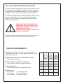
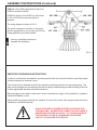
ACCU-Pro
MODEL 670
SEMI-AUTOMATIC
BEDKNIFE GRINDER
ASSEMBLY
AND
SERVICE
MANUAL
WARNING
You must thoroughly read and understand this
manual before assembling or maintaining the
equipment, paying particular attention to the
Warning & Safety instructions.
1
6707954 (8-01)
SAFETY INSTRUCTIONS
Safety Awareness Symbols are inserted into this
manual to alert you to possible Safety Hazards.
Whenever you see these symbols, follow their
instructions.
The Caution Symbol identifies special instructions
or procedures which, if not correctly followed, could
result in damage to or destruction of equipment.
The Warning Symbol identifies special instructions
or procedures which, if not strictly observed, could
result in personal injury.
1. KEEP GUARDS IN PLACE and in working
order.
12. DON'T OVERREACH. Keep proper footing and
balance at all times.
2. REMOVE WRENCHES AND OTHER TOOLS.
13. MAINTAIN GRINDER WITH CARE. Follow
instructions in Service Manual for lubrication and
preventive maintenance.
3. KEEP WORK AREA CLEAN.
4. DON'T USE IN DANGEROUS ENVIRONMENT.
Don't use Grinder in damp or wet locations, or
expose it to rain. Keep work area well lighted.
5. KEEP ALL VISITORS AWAY. All visitors
should be kept a safe distance from work area.
6. MAKE WORK AREA CHILD-PROOF with
padlocks or master switches.
14. DISCONNECT POWER BEFORE SERVICING.
15. REDUCE THE RISK OF UNINTENTIONAL
STARTING. Make sure the switch is OFF before
plugging in the Grinder.
16. USE RECOMMENDED ACCESSORIES. Consult
the manual for recommended accessories. Using
improper accessories may cause risk of personal
injury.
7. DON'T FORCE THE GRINDER. It will do the job
17. CHECK DAMAGED PARTS. A guard or other
better and safer if used as specified in this
part that is damaged or will not perform its
manual.
intended function should be properly repaired or
replaced.
8. USE THE RIGHT TOOL. Don't force the Grinder
or an attachment to do a job for which it was not
18. KNOW YOUR EQUIPMENT. Read this manual
designed.
carefully. Learn its application and limitations as
well as specific potential hazards.
9. WEAR PROPER APPAREL. Wear no loose
clothing, gloves, neckties, or jewelry which may
19. KEEP ALL SAFETY DECALS CLEAN AND
get caught in moving parts. Nonslip footwear is
LEGIBLE. If safety decals become damaged or
recommended. Wear protective hair covering to
illegible for any reason, replace immediately. Refer
contain long hair.
to replacement parts illustrations in Service
Manual for the proper location and part numbers
10. ALWAYS USE SAFETY GLASSES.
of safety decals.
11. SECURE YOUR WORK. Make certain that the
20. DO NOT OPERATE THE GRINDER WHEN
bedknife is securely fastened with the
UNDER THE INFLUENCE OF DRUGS,
electromagnets provided before operating.
ALCOHOL, OR MEDICATION
2
SAFETY INSTRUCTIONS
IMPROPER USE OF GRINDING WHEEL MAY CAUSE
BREAKAGE AND SERIOUS INJURY.
Grinding is a safe operation if the few basic rules listed below are followed.
These rules are based on material contained in the ANSI B7.1 Safety Code for
"Use, Care and Protection of Abrasive Wheels". For your safety, we suggest
you benefit from the experience of others and carefully follow these rules.
DO
DON'T
1. DO always HANDLE AND STORE wheels in a
CAREFUL manner.
1. DON'T use a cracked wheel or one that HAS
BEEN DROPPED or has become damaged.
2. DO VISUALLY INSPECT all wheels before
mounting for possible damage.
2. DON'T FORCE a wheel onto the machine OR
ALTER the size of the mounting hole - if
wheel won't fit the machine, get one that will.
3. DO CHECK MACHINE SPEED against the
established maximum safe operating speed
marked on wheel.
4. DO CHECK MOUNTING FLANGES for equal
and correct diameter.
5. DO USE MOUNTING BLOTTERS when
supplied with wheels.
3. DON'T ever EXCEED MAXIMUM
OPERATING SPEED established for
the wheel.
4. DON'T use mounting flanges on which the
bearing surfaces ARE NOT CLEAN, FLAT
AND FREE OF BURNS.
6. DO be sure WORK REST is properly adjusted.
5. DON'T TIGHTEN the mounting nut
EXCESSIVELY.
7. DO always USE A SAFETY GUARD
COVERING at least one-half of the grinding
wheel.
6. DON'T grind on the SIDE OF THE WHEEL
(see Safety Code B7.2 for exception).
8. DO allow NEWLY MOUNTED WHEELS to run
at operating speed, with guard in place, for at
least one minute before grinding.
7. DON'T start the machine until the WHEEL
GUARD IS IN PLACE.
8. DON'T JAM work into the wheel.
9. DO always WEAR SAFETY GLASSES or some 9. DON'T STAND DIRECTLY IN FRONT of a
type of eye protection when grinding.
grinding wheel whenever a grinder is started.
10. DO TURN OFF COOLANT before stopping to
avoid creating an out-of-balance condition.
10. DON'T FORCE GRINDING so that motor
slows noticeably or work gets hot.
AVOID INHALATION OF DUST generated by grinding and cutting operations.
Exposure to dust may cause respiratory ailments. Use approved NIOSH or
MSHA respirators, safety glasses or face shields, and protective clothing.
Provide adequate ventilation to eliminate dust, or to maintain dust level
below the Threshold Limit Value for nuisance dust as classified by OSHA.
3
This machine is intended for grinding the bedknife from a reel mowing
unit ONLY. Any use other than this may cause personal injury and void
the warranty.
This machine is intended for indoor use only.
To assure the quality and safety of your machine and to maintain the
warranty, you MUST use original equipment manufactures replacement
parts and have any repair work done by a qualified professional.
ALL operators of this equipment must be thoroughly trained BEFORE
operating the equipment.
Do not use compressed air to clean grinding dust from the machine. This
dust can cause personal injury as well as damage to the grinder. Do not use a
power washer to clean the machine.
Low Voltage Relay
The grinder is equipped with a low voltage relay which
is factory preset at 100 VAC. If the power supply line
does not deliver 100 VAC power under load, the relay
will open and trip out the starter. If this occurs, your
power supply line is inadequate and must be correct
before proceeding further with the grinder.
ADJUSTMENT OF THE LOW VOLTAGE RELAY MAY CAUSE ELECTRICAL COMPONENT
FAILURE. ADJUSTMENT OF THE LOW
VOLTAGE RELAY WILL VOID ALL
ELECTRICAL COMPONENT WARRANTY.
CONTENTS
Assembly...................................................................................................... Page 6 - 12
Maintenance ................................................................................................ Page 13 - 15
Adjustments ................................................................................................. Page 16-23
Troubleshooting ........................................................................................... Page 24-33
Electrical Schematic ..................................................................................... Page 34
Parts List. ..................................................................................................... Page 35-48
SPECIFICATIONS
Electrical Requirements ............................................................ 115V 50/60 Hz, 15-amp circuit
Net Weight ....................................................................................................... 780 lbs [354 kg]
Shipping Weight ............................................................................................... 920 lbs [417 kg]
Maximum Grinding Length ................................................................................ 34 in. [863 mm]
Sound Level..................................................................................................... Less than 75 Dba
4
SKILL AND TRAINING REQUIRED FOR SERVICING
This Service Manual is designed for technicians who have the necessary mechanical and electrical knowledge and skills to reliably test
and repair the ACCU-Pro Bedknife Grinder. For those without that
background, service can be arranged through a local distributor.
This Manual presumes that you are already familiar with the normal
operation of the Grinder. If not, you should read the Operators
Manual, or do the servicing in conjunction with someone who is
familiar with its operation.
PERSONS WITHOUT THE NECESSARY
KNOWLEDGE AND SKILLS SHOULD NOT
REMOVE THE CONTROL BOX COVER OR
ATTEMPT ANY INTERNAL
TROUBLESHOOTING, ADJUSTMENTS, OR
PARTS REPLACEMENT!
If you have questions not answered in this manual, please call your
distributor. They will contact the manufacturer if necessary.
TORQUE REQUIREMENTS
Throughout this manual we refer to torque requirements as
"firmly tighten" or the like. For more specific torque values, refer
to the information below.
GRADE 2
Bolts Going into a Nut, or Into a Thread Hole in Steel.
Refer to table at the right.
Bolts Going into a Thread Hole in Aluminum.
Use the Grade 2 values in the table at the right.
Socket-Head Screws
Use the Grade 8 values in the table at the right.
Machine Screw
No. 6 Screws:
No. 8 Screws:
No. 10 Screws:
11in.-lbs [0.125 kg-m]
20 in.-lbs [0.23 kg-m]
32 in.-lbs [0.37kg-m]
5
GRADE 5 GRADE 8
SMOOTH
HEAD
3 MARKS
on HEAD
6 MARKS
on HEAD
1/4 In.
thread
6 ft-lbs
(0.8 kg-m)
9 ft-lbs
(1.25 kg-m)
13 ft-lbs
(1.8 kg-m)
5/16 In.
thread
11 ft-lbs
(1.5 kg-m)
18 ft-lbs
(2.5 kg-m)
28 ft-lbs
(3.9 kg-m)
3/8 In.
thread
19 ft-lbs
(2.6 kg-m)
31 ft-lbs
(4.3 kg-m)
46 ft-lbs
(6.4 kg-m)
7/16 In.
thread
30 ft-lbs
(4.1 kg-m)
50 ft-lbs
(6.9 kg-m)
75 ft-lbs
(10.4 kg-m)
1/2 In.
thread
45 ft-lbs
(6.2 kg-m)
75 ft-lbs
115 ft-lbs
(10.4 kg-m) (15.9 kg-m)
ASSEMBLY INSTRUCTIONS
NOTE: For clarity, the Grinder is shown on the following
pages without the optional carriage bellows installed.
UNPACK THE CARTONS
NOTE: Before you install the machine, read the following
assembly procedure completely. Then study "Getting to
Know Your Bedknife Grinder" in the Operators Manual.
Use care when unpacking. Double-check the packing
cartons for any miscellaneous items before discarding.
Inspect all items for shipping damage as they are
removed from the shipping containers. If you find any
damage, notify the carrier's claims agent and do not
proceed further until the damage has been inspected by
the agent. Refer also to the "Shipping and Receiving
Instructions" packed with the unit.
FIG. 1
Remove the Coolant Tank carton from under the machine.
Remove the control box from under the machine. Be
careful of the electrical wiring which was preconnected at
the factory.
Install the Control Box
Attach the control box to the right front end of the
machine, using the two 3/8-16 x 5/8" hex-head bolts, and
two lock washers provided. See FIG. 1. The fasteners
are shipped in an envelope inside the control box carton.
Remove the Grinder from the Pallet
To remove the Grinder from the wood pallet:
1. Unbolt the brackets that hold each end of the
Grinder legs to the bottom of the pallet.
2. The Grinder's four leveling feet (FIG. 2) are seated in
countersunk holes in the pallet. Lift one end of the
machine until both feet are out of their holes.
3. Prop this first end up with sturdy boards or other
supports so the feet remain out of their holes, then lift
the other end and remove the Grinder from the pallet.
THE GRINDER WEIGHS 780 LBS
[354 KG]. TO LIFT, USE POWER
EQUIPMENT OR GET ADEQUATE
HELP.
Remove the shipping strap that secures the grinding
head and carriage to the left end of the machine during
shipment. Reinstall the wiper plate screw which held the
right end of the strap. Discard the leg screw and the
shipping strap.
6
FIG. 2
ASSEMBLY INSTRUCTIONS (Continued)
LOCATE AND LEVEL THE GRINDER
Set the Grinder on a level concrete floor, on a single
uncracked slab of concrete.
If the unit must be located near a wall, allow adequate
space for operating and servicing. Refer to FIG. 3 for
recommended and alternate locations near a wall.
Place a level on the front carriage rail near the center of
the machine and check the level from left to right. See
FIG. 4A. Adjust the leveling feet until the machine is level.
Place the level across the front and rear carriage rails near
the left end of the machine. See FIG. 4B. Adjust the two
leveling feet on the left end until the rear rail (the one
closest to the coolant tray) is slightly lower than the front
rail--so any coolant on the carriage, main base, or optional
bellows will drain back into the coolant tray.
Place the level across the front and rear carriage rails near
the right end of the carriage bed. Level the right end in
the same way as the left end. For grinding accuracy, the
two ends must have the identical backward slant within +/.01" [.25 mm] so the frame is not twisted.
Recheck the level in both directions. When satisfactory,
tighten the hex jam nuts on the leveling feet securely
against the nuts welded to the bottom of the base. See
FIG. 2. Don't turn the leveling feet when tightening.
FIG. 3
A
Leveling Side-to-Side
Again recheck the level after the nuts are firmly tightened.
FOR GRINDING ACCURACY, THE MACHINE
DOES NOT HAVE TO BE PERFECTLY LEVEL.
HOWEVER, IT IS CRITICAL THAT FRONT-TOBACK LEVELING BE IDENTICAL AT BOTH
ENDS OF THE MACHINE.
INSTALL THE SPINNING HANDLES
Install the spinning handle on the horizontal handwheels.
See FIG. 5. Handle parts are packed in an envelope
taped to the wheel.
FIG. 4
Regular Hex Nut
Lock Nut
FIG. 5
7
ASSEMBLY INSTRUCTIONS (Continued)
APPLY POWER
BEFORE YOU APPLY POWER TO THE
GRINDER, REFER TO THE "IMPORTANT
GROUNDING INSTRUCTIONS" ON PAGE 9.
115 Volt Model Only. Plug the control box power cord into a
standard 115V AC 15-amp grounded receptacle. See FIG. 7.
FIG. 7
220 Volt Model Only. For 220 Volt Applications order Part
No. 6700951, which includes a 220 to 110 Volt Step Down
Transformer. See Details on page 9.
IT IS RECOMMENDED THAT THIS ACCUPRO BEDKNIFE GRINDER HAS ITS OWN
PERMANENT POWER CONNECTION FROM
THE POWER DISTRIBUTION PANEL, WITH
NO OTHER MAJOR POWER DRAW
EQUIPMENT ON THE SAME LINE.
IT IS REQUIRED THAT THE POWER
DELIVERED TO THIS GRINDER IS 115 VAC 15 AMPS. THE TOLERANCE ON THIS
POWER REQUIREMENT IS +/- 5%.
THEREFORE THE MINIMUM VOLTAGE
REQUIREMENT IS 109VAC WITH 15 AMPS.
VOLTAGE MUST BE CHECKED WITH ALL
EQUIPMENT UNDER LOAD (OPERATING) ON
THE CIRCUIT.
The grinder is equipped with a low voltage relay
which is factory preset at 100 VAC. If the power
supply line does not deliver 100 VAC power under
load, the relay will open and trip out the starter. If
this occurs, your power supply line is inadequate
and must be correct before proceeding further with
the grinder.
DO NOT OPERATE THIS GRINDER WITH
AN EXTENSION CORD.
PROPER GROUNDING OF THE RECEPTACLE GROUND IN YOUR BUILDING MUST
BE VERIFIED. IMPROPER GROUNDING IN
YOUR BUILDING MAY CAUSE THE GRINDER
TO MALFUNCTION.
ADJUSTMENT OF THE LOW
VOLTAGE RELAY MAY CAUSE
ELECTRICAL COMPONENT
FAILURE. ADJUSTMENT OF
THE LOW VOLTAGE RELAY
WILL VOID ALL ELECTRICAL
COMPONENT WARRANTY.
FOR 15 AMP RATED LARGE MACHINES
For 0 to 30 Feet from panel to receptacle = Use 14 Ga. Wire.
For 30 to 50 Feet from panel to receptacle = Use 12 Ga. Wire.
For 50 to 80 Feet from panel to receptacle = Use 10 Ga. Wire.
For 80 to 140 Feet from panel to receptacle = Use 8 Ga. Wire.
For 0 to 9 Meters from panel to receptacle = Use 2.5mm Wire.
For 9 to 15 Meters from panel to receptacle = Use 4.0mm Wire.
For 15 to 24 Meters from panel to receptacle = Use 6.0mm Wire.
For 24 to 42 Meters from panel to receptacle = Use 10.0mm Wire.
8
ASSEMBLY INSTRUCTIONS (Continued)
FOR 220 V 50 or 60Hz applications Product No.
6700951 should be ordered.
6700951 includes a 2 KVA 220 Volt Step Down
to 110 volt 50/60 Hz transformer which is
prewired.
The wiring diagram is shown in FIG. 8.
The power cord has no connector. A connector
which is appropriate for your locality and 220 volt,
8 amp application should be installed.
Use only a qualified electrician to
complete the installation.
FIG. 8
IMPORTANT GROUNDING INSTRUCTIONS
In case of a malfunction of breakdown, grounding reduces the risk of electrical shock by providing a path
of least resistance for electrical current.
This Grinder has an electrical cord with an equipment grounding conductor and a grounding plug. The
plug must be plugged into a matching outlet that is properly installed and grounded according to all local
or other appropriate electrical codes and ordinances.
Before plugging in the Grinder, make sure it will be connected to a supply circuit protected by a properlysized circuit breaker or fuse.
Never modify the plug provided with the machine--if it won't fit the outlet, have a proper outlet and circuit
installed by a qualified electrician.
ALWAYS PROVIDE A PROPER ELECTRICAL GROUND FOR
YOUR MACHINE. AN IMPROPER CONNECTION CAN CAUSE A
DANGEROUS ELECTRICAL SHOCK. IF YOU ARE UNSURE OF
THE PROPER ELECTRICAL GROUNDING PROCEDURE,
CONTACT A QUALIFIED ELECTRICIAN.
9
ASSEMBLY INSTRUCTIONS (Continued)
Actuator Mounting
Screw (under the rubber
splash guard)
INSTALL THE OPTIONAL
CARRIAGE BELLOWS (if ordered)
Optional carriage bellows are available to keep excess
grindings, dirt, etc. out of the carriage assembly. To
install the two bellows:
1. Remove the left and right outside leg panels.
2. Remove the shaft seal on each side of the linear
actuator. See FIG. 9. NOTE: When the bellows are
used, the shafts don't get lubricated and the seals
would run dry. They would then become noisy and
not operate properly.
To remove the seals:
a. Crank the carriage all the way toward the
front (that is, toward the operator's position).
b. Remove the actuator mounting screw on top
of the carriage. See FIG. 9. Then push the
carriage toward the right end of the Grinder.
c. Loosen the two set screws in the bearing
pillow block at each end of the drive shaft.
Loosen the two set screws in the drive
coupling at the right end of the carriage.
d. Turn the actuator release lever clockwise 1/2
turn until the actuator is released from the
shaft. See FIG. 9.
e. Slide the drive shaft out the left end of the
machine.
f. Remove the shaft seals from the actuator two screws each.
g. Reinstall the drive shaft. The right end of
the shaft (inside the coupling) should be
1/8 - 1/4" [3 to 6.5 mm] from the end of the
motor shaft. Retighten all set screws.
h. Push the carriage back to the left, and
reattach the actuator with the mounting
screw. See FIG. 9. Turn the actuator
release lever, 1/2 turn.
3. Remove the two rail wiper brackets from each side
of the carriage - two screws each. See FIG. 11.
4. Attach the outer end of each bellows to the Grinder
leg panel. See FIG. 10. Use six bolts, and hex
nuts, at each end. The bolt heads go on the bellows
side of the brackets.
5. Attach the inner end of each bellows to the carriage.
See FIG. 11. Use four L-brackets, (two on each
side of the last bellows fold), six bolts, and two hex
nuts at each end. Nuts are required only for the
lower holes of the L-brackets.
6. Press the bellows down until it snaps onto the
carriage rails.
7. Reattach the left and right outside leg panels.
10
Actuator Bar Assembly
Linear Actuator
Drive Shaft
Seal Plate
Actuator Release Lever
FIG. 9
ASSEMBLY INSTRUCTIONS (Continued)
INSTALL THE COOLANT TANK
Assemble the Coolant Tank as outlined in the instructions
(Part No. 7467909) in the coolant tank carton.
Center the Tank under the Grinder.
Install the 1" I.D. drain tubing over the barbed end of the
plastic adapter on the coolant tray drain. Cut the tubing to
the proper length to reach about 1-1/2" [40 mm] into the
large opening on top of the Coolant Tank. See FIG. 12.
A pre-filter sock is shipped with the Tank. Install it onto the
tubing, using the plastic tie provided. Drop the other end of
the sock into the opening on top of the Tank.
Read the coolant mixing directions and the electrical
warnings in the Coolant Tank instructions.
FIG. 12
THE COOLANT RATIO AS SPECIFIED MUST BE
USED. TO HIGH A CONCENTRATION OR LOW A
CONCENTRATION WILL CAUSE CORROSION
AND PERFORMANCE PROBLEMS.
1. Be sure the COOLANT PUMP switch is OFF. Mix (Part
No. 3708620) coolant in the coolant tank, at a ratio
of 50 parts water to 1 part concentrate. This will take
about 6 gallons of water and 1 pint of concentrate (24
liters of water and 0.5 liter of concentrate).
Refer also to the label on the coolant container, and the
instructions packed with the Coolant Tank.
CHECK THE COOLANT PUMP
Plug the pump motor cord (from the top of the Tank) to the
female connector from the control box.
RISK OF ELECTRICAL SHOCK!
MAKE CERTAIN THAT THE ABOVE
ELECTRICAL CONNECTION IS
SECURED ABOVE AND AWAY FROM
POSSIBLE CONTACT WITH THE
COOLANT.
Turn all control panel switches OFF. Close the guard door
and press START. Press Coolant Pump Switch to ON.
Check that the Coolant System functions properly. Be
prepared to press STOP if there is any problem.
NOTE: If the unit doesn't begin to pump coolant, press the
reset button on the motor contactor inside the control box.
See FIG. 13.
Secure any excess electrical cord to a crossbar on the
underside of the machine.
11
FIG. 13
ASSEMBLY INSTRUCTIONS (Continued)
CHECK THE CARRIAGE TRAVERSE
Move the proximity switch assemblies to about 12" [300 mm]
from the ends of the machine, and tighten their knobs.
Visually check that the grinding head will be able to traverse
to both sides of the machine without contacting any
components.
Turn all control panel switches OFF. Set the TRAVERSE FT/
MIN knob to zero. Close the guard door and press START.
Press CARRIAGE TRAVERSE to ON. Set TRAVERSE FT/
MIN to a low speed, and check that the grinding head runs
through a complete traverse cycle. Be prepared to press
STOP if there is any interference. Watch carefully for
obstructions to the head travel, and check that the grinding
motor cord and proximity switch cords are not stretched.
NOTE: If the unit doesn't begin a traverse cycle, press the
reset button on the motor contactor inside the control box.
See FIG. 13.
CHECK THE GRINDING MOTOR
Turn all control panel switches OFF. Close the guard door to
connect the interlock. Press START. Press Grinding Motor
Switch to ON. Check that the grinding head runs properly.
Be prepared to press STOP if there is any problem.
NOTE: If the grinding head doesn't begin properly, press the
reset button on the motor contactor inside the control box.
See FIG. 13.
CHARGING TO SUPPLEMENTARY POWER SUPPLY
The Supplementary Power Supply (SPS) comes from the
supplier with no charge. When the machine is ready for
operation, plug it in and turn on the SPS. The battery will
charge in six hours. For SPS functions, refer to the separate
manual supplied with the grinder.
MAKE FINAL PREPARATIONS FOR OPERATION
Carefully read the operating instructions in the Operators
Manual.
First, study the pages titled "Getting to Know Your Grinder"
and "General Operating Information" for important
background explanations about the machine and about
bedknife grinding. Then, read the "Operating Instructions"
pages for step-by-step procedures on mounting the
bedknife and grinding its top and front faces.
12
MAINTENANCE
DAILY MAINTENANCE IS SPECIFIED ON PAGE 4
OF THE OPERATOR'S MANUAL, AND IS TO BE
PERFORMED BY THE OPERATOR. LISTED
BELOW ARE PERIODIC MAINTENANCE ITEMS
TO BE PERFORMED BY YOUR COMPANY'S
MAINTENANCE DEPARTMENT:
1. Lift the bellows, (See FIG. 14) if used, and wipe off
the traverse driveshaft and the bearing rails monthly.
When a squeaking noise is coming from the actuator
bearings, follow the lubrication procedure for actuator
and linear bearings. Generally, this will be every
6 months to a year.
FIG. 14
2. Check the gib plate adjustment in the carriage base
every 3 months. See Page 21.
3. Replace the four foam rail wipers (FIG. 15) every 6
months of operation. Note: Wipers are removed if
optional bellows are installed.
4. Clean the interior and the top cover of the Coolant
Tank as necessary and at least every 6 months.
5. Check the brushes on the auto traverse drive motor
once every 24 months. Replace as necessary.
Carriage
Rails
FIG. 15
THE UNINTERUPTABLE POWER SUPPLY (UPS)
WHICH IS USED AS A BACKUP TO HOLD THE
BEDKNIFE TO THE ELECTROMAGNETS DURING
A POWER INTERUPTION HAS A BATTERY.
THIS BATTERY HAS A THREE YEAR LIFE AND
MUST BE REPLACED AFTER THREE YEARS OF
SERVICE LIFE. SEE THE PARTS LIST FOR
REPLACEMENT BATTERY PART NUMBER.
13
MAINTENANCE (Continued)
LUBRICATION
Actuator and Linear Bearings
Do the following every six months (or more often if the linear
actuator seals are squeaking):
1. Thoroughly clean the carriage rails, drive shaft, and
shaft seals. Wipe the shafts and seals thoroughly with
a clean rag.
While cleaning, traverse the carriage several times to
clean the full length of the drive shaft and rails.
2. Flood-spray all three shafts with WD-40 or an equivalent
lubricant (do not use a Teflon-based lubricant) until
lubricant drips off the shafts. Then run the carriage back
and forth through its range of travel, to carry lubricant
onto the outer surface of the actuator bearings and the
inner surface of the seals.
NOTE: Because of the flood of lubricant, you may find
that the actuator slips and traversing is erratic or stalls.
This is not a problem, as it will be corrected in Step 3.
3. With a clean rag, wipe the excess lubricant from the
shafts. Run the carriage back and forth through its
range of travel, and wipe the shafts after each
traverse. Repeat until the shafts feel dry.
IMPORTANT: If the machine will be shut down for more than
one month, flood the shafts and other appropriate parts with
lubricant as outlined above, and leave the lubricant in place
until the unit will be used again. Then repeat the above
lubrication procedure before operating.
14
MAINTENANCE (Continued)
CLEANING AND MAINTENANCE GUIDELINES FOR POLYCARBONATE WINDOWS
Cleaning Instructions
DO NOT USE GASOLINE
Adherence to regular and proper
cleaning procedures is recommended
to preserve appearance and performance.
Washing to Minimize Scratching
Wash polycarbonate windows with a mild dish washing liquid detergent and lukewarm water, using a
clean soft sponge or a soft cloth. Rinse well with clean water. Dry thoroughly with a moist
cellulose sponge to prevent water spots. Do not scrub or use brushes on these windows. Also,
do not use butyl cellosolve in direct sunlight.
Fresh paint splashes and grease can be removed easily before drying by rubbing lightly with a
good grade of VM&P naphtha or isopropyl alcohol. Afterward, a warm final wash should be made,
using a mild dish washing liquid detergent solution and ending with a thorough rinsing with clean
water.
Minimizing Hairline Scratches
Scratches and minor abrasions can be minimized by using a mild automobile polish. Three such
products that tend to polish and fill scratches are Johnson paste Wax, Novus Plastic Polish #1 and
#2, and Mirror Glaze plastic polish (M.G. M10). It is suggested that a test be made on a corner of
the polycarbonate window with the product selected following the polish manufacturer's instructions.
Some Important "DON'TS"
¨
DO NOT use abrasive or highly alkaline cleaners on the polycarbonate windows.
¨
Never scrape polycarbonate windows with squeegees, razor blades or other sharp
instruments.
Benzene, gasoline, acetone or carbon tetrachloride should NEVER be used on
polycarbonate windows.
¨
DO NOT clean polycarbonate windows in hot sun or at elevated temperatures.
Graffiti Removal
• Butyl cellosolve, (for removal of paints, marking pen inks, lipstick, etc.)
• The use of masking tape, adhesive tape or lint removal tools works well for lifting off old
weathered paints.
• To remove labels, stickers, etc., the use of kerosene, VM&P naphtha or petroleum spirits is
generally effective. When the solvent will not penetrate sticker material, apply heat (hair
dryer) to soften the adhesive and promote removal.
GASOLINE SHOULD NOT BE USED!
15
ADJUSTMENTS
TO REPLACE THE LINEAR ACTUATOR BEARINGS
NOTE: Do not remove the linear actuator from the drive
shaft. Only remove the bearings from the actuator block.
1. Crank the horizontal handwheel until the carriage is
all the way forward (toward the operator position).
2. Turn the actuator release lever 1/2 turn clockwise
to release the linear actuator bearings from the
drive shaft. Slide the actuator release lever out
of actuator bar assembly by loosening the retainer
shaft collar, which preloads the holding spring.
See FIG. 18A and 18B.
3. Remove the feed screw guide two mounting screws
and slide the grinding head assembly back. Lift the
rubber splash guard to expose the actuator mounting
screw (FIG. 17) on the top side of the carriage base.
Remove the mounting screw, to disconnect the linear
actuator from the carriage. Slide the carriage
assembly to one side.
4. Disconnect the shaft seal plate (FIG. 17) from each
side of the linear actuator. Slide the seals down the
drive shaft until they are out of the way. (If the optional
carriage bellows were installed, the shaft seals may
already have been removed).
5. Remove the shoulder bolts holding the six bearings
(three on each side) to the actuator block. Remove
the old bearings and discard them, but save the inside
washers and shoulder bolts.
Actuator Mounting
Screw (under the rubber
splash guard)
Actuator Bar Assembly
Linear Actuator
Drive Shaft
Seal Plate
Actuator Release Lever
FIG. 17
Inspect the hole from which the bearing and shoulder
bolt were removed, for foreign matter. Clean
thoroughly.
6. Wipe the drive shaft clean and dry.
If oil is left on the drive shaft, the pulling
force may have to be set too high in the
following procedure. This will shorten
the bearing life.
Actuator Engaged
FIG. 18A
7. Insert the shoulder bolts through the new bearings
and through the inside washers (saved in Step 6).
Then install the complete bearing assemblies into the
actuator block and tighten the shoulder bolts.
Be very careful not to cross-thread the
bearing bolts!
Reinstall the shaft seal plates if applicable. Be sure
the seal plates are mounted concentric to the drive
shaft.
16
Actuator Released
FIG. 18B
ADJUSTMENTS (Continued)
TO REPLACE THE LINEAR ACTUATOR BEARINGS
8. Slide the carriage over the actuator, and line up the
hole in the carriage with the tapped hole in the top of
the actuator block. Insert the actuator mounting screw
through the self-adjusting bearing, and tighten the screw.
Hold the drive shaft from
rotating while you check
the pulling force.
9. Install the two feed screw guide mounting screws.
Install the actuator release lever into the actuator bar
assembly. Turn the actuator release lever
counterclockwise 1/2 turn to engage the actuator.
10. Connect a spring scale so it pulls on the carriage
parallel to the drive shaft. Hold the drive shaft from
rotating while you pull on the carriage. See FIG. 19.
FIG. 19
To overcome the actuator, the pulling force should be
45 to 60 lbs (20-27 kg), with 50 lbs (23 kg) being ideal.
If not within those specifications, the actuator tension
must be adjusted. See "Adjusting the Pulling Force"
below.
Exceeding 60 lbs force won't greatly
improve drive performance - and it will
shorten the bearing life.
Adjusting the Pulling Force
If the pulling force is not within specification (Step 10 above),
adjust it:
1. With the actuator bearings engaged to the drive shaft,
readjust the two outboard screws with springs that hold
the actuator together. To reach these screws, you must
remove the actuator bar assembly. See FIG. 17.
Turn each outboard screw an equal amount when
resetting. Turn clockwise for more tension.
2. Check the force again (repeat Step 10 above).
Continue adjusting and rechecking until within
specification.
NOTE: The factory-adjusted position to reach tension
specifications is to compress the spring until there is
.22 in. (5.5 mm) clearance between the underside of
the washer and the actuator block. See FIG. 20. Use
this as a starting point unless you are already close to the
specified tension.
3. When the tension adjustment is correct, reinstall the
actuator bar assembly and actuator release lever.
17
FIG. 20
If the actuator release lever is
tightened too much, it will
contact the outboard screw
heads and override their
adjustment, which could
cause a traverse malfunction.
Make certain that you have
full engagement when you
reengage the actuator.
ADJUSTMENT (Continued)
TO REPLACE THE CARRIAGE LINEAR BEARINGS
NOTE: Set a small bench or table near the center
front of the machine for use in the following procedure.
1. Remove the optional carriage bellows (if used) from
the carriage. Remove the actuator release lever from
the linear actuator.
2. Remove the complete carriage assembly from the
machine:
A. Remove the two feed screw guide mounting screws
and pull the grinding head assembly back. Lift the
rubber flap and expose the actuator mounting screw
(FIG. 22) on the top side of the carriage base.
Remove the screw, to disconnect the actuator from
the carriage.
B. Remove the bolts which secure the front and rear
carriage rails to the Grinder base (six screws for
each rail, accessible from beneath the machine).
Actuator Mounting
Screw (under the rubber
splash guard)
Actuator Bar Assembly
The carriage assembly weighs
about 50 lbs (23 kg). If necessary,
get help for the following steps.
3.
4.
5.
6.
C. Lift the complete assembly (carriage, carriage
shafts, and grinding head) out onto the table in front
of the Grinder. Be careful you don't damage the
motor cord.
Lift the carriage and slide the rails out of the bearings,
one at a time.
Remove the three linear bearing pillow blocks (four
screws each) from the bottom of the carriage, and
discard them.
One at a time, slide the three new linear bearing pillow
blocks onto a carriage rail.
Adjust the tension screw (FIG. 23) on the side of each
bearing block so that when you radially rotate the pil
low block around the carriage (See FIG. 24) rail there
is no free play between the bearing and rail. You should
feel a strong drag.
Repeat this adjustment to all three pillow blocks, and
then remove the pillow blocks from the carriage rail.
NOTE: The tension is too tight if you feel a cogging
action when you rotate a pillow block around the rail. This
cogging is caused by the bearing skidding on the rail.
Rocking the bearing block back and forth should be a
smooth uniform motion.
Bearings which are too tight or too loose will
cause poor grinding quality. Bearings which
are too tight will also have a much shorter life,
and could damage the rail.
18
Linear Actuator
Drive Shaft
Seal Plate
Actuator Release Lever
FIG. 22
Carriage
Tension
Adjustment
Screw
Radial Rotation
ADJUSTMENTS (Continued)
TO REPLACE THE CARRIAGE LINEAR BEARINGS
7. Attach the three linear bearing pillow blocks loosely to
the bottom of the carriage, with their tension adjustment
screws (FIG. 23) facing outward.
8. Clean the carriage rails.
NOTE: The two rails are interchangeable and are also
reversible (end-for-end).
9. Insert a rail through the rear two pillow blocks, and align
the rear pillow blocks to each other with a straight edge
laid along their sides. See FIG. 25. When aligned, tighten
the four socket-head screws which hold each rear pillow
block. Slide the other carriage shaft through the front
bearing, but do not tighten the socket head screws.
10. Lift the complete carriage assembly back onto the
Grinder main base, and secure the rear carriage rail
to its V-groove bosses with the six bolts.
11. With the front rail resting in the V-groove bosses and the
carriage approximately centered on the machine, tighten
the two outside socket-head screws which secure the front
pillow block. Lift the front of the carriage, and tighten the
two inside pillow-block screws. Secure the front carriage
rail to its V-groove bosses with the six bolts.
12. Recheck the bearing tension. The tension is correct
when you try to lift the carriage and can feel no free
carriage movement up or down.
Check for excessive carriage-traverse load by using a
spring scale to pull on the carriage parallel to the drive
shaft (as in FIG. 19). There should be only about a 3- to
5- lb. pulling force.
To double-check, manually slide the carriage assembly
from one end of its travel to the other. There should
be uniform resistance through the full range of travel.
13. Slide the linear actuator under the carriage, and line up
the hole in the carriage with the tapped hole in the top of
the actuator block. Insert the actuator mounting screw
through the self-aligning bearing, and tighten it.
Be careful not to cross-thread the screw.
14. Reinstall the feed screw guide mounting screws and then
the actuator release lever into the linear actuator.
15. If being used, reattach the two carriage bellows. Refer
to the assembly section of this manual.
19
Rear Pillow Blocks
Straightedge
Underside of
Carriage
FIG. 25
ADJUSTMENT (Continued)
TO ALIGN THE MOTOR SHAFT AND DRIVE SHAFT
There must be 0.12 to 0.50 in. (3.0 to 12.7 mm) end
clearance between the traverse motor output shaft and
the drive shaft, inside the flexible coupling (FIG.27).
To prevent drive shaft "whipping" at higher traverse
speeds, the two shafts must be aligned so they are
concentric within .010 in. [0.25 mm]. To align:
1. Loosen the two set screw in the coupling.
2. Remove the cover on the outside of the right
leg.
3. Loosen the two bolts which secure the motor
assembly to the leg.
4. Visually align the two shafts, then tighten the
motor mounting bolts. Reinstall the leg cover.
5. Check that the spiral gaps in the flexible
coupling are equally spaced, with no compression
or extension load on the coupling, then tighten the
coupling screws.
6. Check that the bearing load block is at 90o
to the drive shaft (within +/- 1/4 degree). Use a
precision square held against the bearing
shoulder and the rear rail, as in FIG. 26.
TO ALIGN THE REAR RAIL AND DRIVE SHAFT
The rear carriage rail and the drive shaft must be
precisely aligned:
1. Loosen the two bolts holding the bearing support
blocks at each end of the drive shaft. FIG. 28.
2. Align the drive shaft and rear carriage rail (FIG.
29) so the distance between their facing surfaces
is 3.375"+/- .010 [85.75 mm +/- 0.25]. See FIG.
29.Then tighten the support block bolts.
3. Check that the bearing support blocks are still at
90o to the drive shaft (within +/- 1/4 degree).
Use a precision square held against the bearing
shoulder and the rear rail.
4. If you have difficulty obtaining the above alignment,
check the straightness of the carriage rails (see
below).
NOTE: The vertical and horizontal straightness of the
rails is very accurately set at the factory, so they are
unlikely to be incorrect. Contact the factory if you suspect a problem after making the following tests.
If the drive shaft is adjusted, you
may have to realign the motor shaft
and drive shaft (see above).
20
ADJUSTMENT (Continued)
TO ADJUST THE PROXIMITY SWITCHES
For the proximity switches to work properly and
reverse the direction of the carriage at each end of a
traverse, a distance of 3/16 in. +/- 1/32 [4.75 mm +/
- 0.75] must be maintained between the top of the
switch and the actuator bracket on the bottom of the
carriage. See FIG. 33.
To adjust the clearance, loosen one of the switch
mounting nuts while tightening the other.
FIG. 33
TO ADJUST THE GIB PLATE
The gib plate must be readjusted occasionally to
eliminate free play. Otherwise the grinding head can
move from side to side, and the bedknife may be
ground unevenly.
The gib must allow the carriage to be cranked freely
forward and back without any side play.
See FIG. 34. To adjust:
1. Crank the carriage all the way forward
(toward the operator position).
2. Tighten the front gib screw until the carriage
has no side play but the horizontal handwheel
can still be cranked.
3. Crank the carrige gradually back (away from
the operator position), and adjust the
remaining gib screws as you go.
21
FIG. 34
ADJUSTMENTS (Continued)
TO ELIMINATE CARRIAGE INFEED BACKLASH
If there is backlash in the carriage infeed handwheel
(FIG. 35), there are two adjusting points to check:
1. Conical washers behind the shaft adjusting nut:
A. Unscrew the shoulder bolt.
B. Hold the horizontal handwheel, and turn the
shaft adjusting nut counterclockwise until the
conical washers are touching each other.
Continue turning the nut counterclockwise
until the next notch is centered over the
shouder-bolt hole. Then turn the nut one
notch (40o) further.
C. Reinstall the shoulder bolt to lock the nut in
position.
2. Washers behind the handwheel:
A. Remove the setscrew holding the calibration
ring to the handwheel.Go through the set
screw hole and loosen the setscrew holding
the handwheel to the shaft (about one-half
turn).
B. Tighten the hex nut which secures the hand
wheel to 100 in.-lbs [1.15 kg-m], then back it
off 1/2 turn.
C. Check for .015 in. [0.4 mm] gap between the
wave washer and flat washer. See the insert
to FIG. 35. Readjust the hex nut if
necessary.
D. Tighten the set screw holding the handwheel
to the shaft. Reinstall and tighten the
calibra tion ring setscrew.
22
FIG. 35
ADJUSTMENTS (Continued)
POTENTIOMETER ADJUSTMENTS TRAVERSE DRIVE CONTROL (TDC)
Min. Speed--Factory set at full (CCW) 8:30. Do not change this setting.
(Right Traverse) Forward Torque--Factory set at full (CW) 4:30. Do not change this setting.
(Left Traverse) Reverse Torque--Factory set at full (CW) 4:30. Do not change this setting.
IR COMP--Factory set to 9:00. Regulation of a traverse motor may be improved by slight adjustment of the IR
COMP trim pot clockwise from its factory-set position. Overcompensation causes the motor to oscillate or to
increase speed when fully loaded. If you reach such a point, turn the IR COMP trim pot counterclockwise until
the symptoms disappear.
Max. Speed--Set at 3:30 for maximum voltage of 90 Volts DC to the traverse motor. When voltage is above 90
volts DC, the traverse motor will start to pulsate and not run smoothly.
(Right Traverse) Forward Acceleration--Factory set at full (CCW) 8:30. Do not change this setting.
(Left Traverse) Reverse Acceleration--Factory set at full (CCW) 8:30. Do not change this setting.
(DB) Dead Band is the potentiometer setting for the 50 or 60 Hz cycle control. Factory set to 9:00, works for
both 50 and 60 Hz. Do not change this setting.
Calibrating the DWELL TIME rotary DIP switch adjusts the amount of time the process remains in the stop
position after a limit switch is actuated. The DWELL TIME range is adjustable from 0 - 4 seconds. A DIP switch
setting of 0 sets the DWELL TIME to 0 seconds, while a setting of 9 sets the DWELL TIME to 4 seconds.
Dwell time is preset to #2 setting for a 1 second dwell time when reversing at each end of stroke. A setting of 4,
sets the dwell time at 2 seconds, etc.
Diagnostic LED's indicate the function that is currently being performed:
3:00
6:00
*
9:00
*
POWER indicates that ac power is being applied to the control.
FORWARD indicates that the process is running in the forward direction (traversing left).
REVERSE indicates that the process is running in the reverse direction (traversing right).
PROX 1 FWD LIMIT lights when the forward
limit switch is actuated (left prox).
PROX 2 REV LIMIT lights when the reverse limit
switch is actuated (right prox).
DWELL lights when the process remains
stopped after a proximity switch is actuated.
12:00
*
*
*
*
Potentiometer
Clock Orientation
23
TROUBLESHOOTING
ELECTRICAL MAIN POWER
--ELECTRICAL---PROBLEM-Grinding motor
do not function
(no apparent
power to machine).
--POSSIBLE CAUSE--
--REMEDY--
A--Grinding Motor Switch (GMS)
is not on.
Turn switch on.
B--Main power source breaker
is tripped, power source switch
is off, or grinder is not plugged
in.
Reset breaker, turn switch on
and plug machine in.
--REASON--
Press System Start Switch.
C--System Start Switch (SSS) is
not on.
Close the guard door.
Because the guard door is
interlocked to the grinding
motor, the grinding motor
will not operate if door is
open.
Check status of the low voltage
relay inside the control box.
If "norm" light is lit, relay is
satisfied and line voltage is
acceptable.
If "trip" light is lit, line voltage
to the grinder is inadequate
and must be corrected.
D--Guard door is not closed
E--Insufficient Line Voltage to
power the low voltage relay.
F--Voltage not going to magnetic starter.
Solenoid in magnetic starter
does not pull in.
Solenoid pulls in, but no voltage
out of magnetic starter.
G--Voltage is not going through
interlock relay.
With the volt meter set on AC
AC voltage power source
voltage, check L1 (black) to L2
required.
(white) for lines coming in of 115
volt. Check power source fuse.
Check for loose connections on These wires control
magnetic starter. Check for 115 magnetic starter voltage for
Volts AC across starter coil A1
main power.
to A2. NOTE: Contactor clicks
when engaging.
Check for 120 volt AC between
terminals T1 (black) and T3
(white). T1 and T3 are main
power out lines. NOTE: T2 is
jumpered to L3. Check reset
overload on starter by pushing
down on blue button. Check
terminal connections between
contactor and overload relay. If
no voltage on output, replace
magnetic starter.
Check for 115 VAC at incoming
side of relay. Terminals 4 & 8.
Check for 115 VAC at output
side of relay terminals 2 & 6.
Checks must be done with
guard door close, Relay Coil
engaged.
24
Overload may have been
tripped when moving
machine or machine
grinding head motor
overload or electrical power
surge.
TROUBLESHOOTING (Continued)
TRAVERSING
--ELECTRICAL---PROBLEM--
--POSSIBLE CAUSE--
--REMEDY-Reset dwell time on traverse
control board as required; one
increment increases dwell time
by 1/2 second. See Page 50.
Insufficient hesitation
at carriage stops
prior to reversing
traverse direction for
relief grinding.
The dwell time on the traverse
drive control not set properly.
If the carriage
traverses to one end
of stroke or the other
and it stops and does
not reverse direction .
Proximity switch is not working First check to see if proximity
light comes on when placing a
properly or wire connections
steel piece over the prox
are loose.
switch. When the light is on it
means that there is electricity
coming to proximity switch.
Left proximity (PROX 1) check
Traverse Drive Control (TDC)
between terminals #14 (black
wire) and #15 (brown wire)
Right proximity (PROX 2)
check (TDC) between terminals #13 (black wire) and #15
(brown wire).
Replace proximity switch if the
voltages do not read as above.
If the carriage
traverses past the
proximity switch and
keeps on traversing
in same direction.
Traverse changes
directions erratically
while running in
traverse cycle.
--REASON--
The light coming on shows
the proximity is getting
electrical contact.
Proximity light on-0 Volts DC
Proximity light off-12 Volts DC
Proximity light on-0 Volts DC
Proximity light off-12 Volts DC
The two proximity switches
have been reversed on the
slide bar.
Reverse the switch assembly
on the slide bar
This will only happen if the
main reversing board has
been replaced and not
rewired to electrical diagram.
Proximity switch has failed
Make sure the proximity light is
coming on when placing a steel
piece over the prox switch.
Check proximity spacing to the
sensor. If no light, first check
adjustment section for proximity
setting. If there is a light, it
means that there is electricity
coming to the proximity switch.
Left proximity (PROX 1) check
(TDC) between terminals #14
(black wire) and #15 (brown
wire).
Right proximity (PROX 2) check
(TDC) between terminals #13
(black wire) and #15 (brown
wire).
Replace proximity switch if the
voltages do not read as above.
Proximity light on--0 Volts DC
Proximity light off-12 Volts DC
Loose wire to proximity switch. Check wire connections from
the proximity switches and
tighten down screws.
25
Proximity light on--0 Volts DC
Proximity light off-12 Volts DC
A loose wire connection will
give intermittent electrical
contact.
TROUBLESHOOTING (Continued)
--PROBLEM-Traverse motor
does not work.
TRAVERSING
--POSSIBLE CAUSE--
--REMEDY--
--REASON--
A--Traverse Motor Switch is
not on.
Turn on motor switch.
B--Blown fuse.
Replace the 2 amp slo-blo
fuse on the control board and
decrease stock removal rate.
Extremely heavy grinding
cuts cause excessive
loading of the motor.
Replace actuator bearings if
they are worn and do not
rotate freely. (For more detail,
see actuator maintenance in
the adjustment section of the
manual.)
Worn and binding actuators
causes heavy loading to
motor.
Replace the lineal bearings in
the main carriage. Carriage
should traverse freely with a 3
lb. maximum loading. Also
check for excessive bearing
preload. (For more detail see
carriage bearing replacement
in the adjustment section of
the manual.)
Grinding grit over a period
of time does get into the
lineal bearings and causes
excessive drive torque of
carriage.
C--No voltage going to motor.
Check for 90 volt DC at the
circuit board leads going to the
motor. Across terminals A1
and A2, check reading with a
voltage meter. When there is
voltage from the circuit board
but DC motor does not run,
check wiring and connections.
The voltage reading varies
with speed pot setting.
NOTE: Make sure speed pot
setting is towards the maximum dial reading for 90 volts.
Check for incoming voltage at
L1 to L2 for at least 105 Volts
AC Red power light is on.
This checks to see that
voltage is getting to the
control board.
D--Bad traverse motor.
Remove the brushes one at a
time and maintain orientation
for reinsertion. See if brush is
worn short 3/8" [9.5 mm]
minimum length, and look at
wear pattern on commuter for
arcing. Replace brushes if
necessary. Replace motor if
brushes are good.
Remove wires from A1 to A2
from the spin motor. Check
with the ohm meter for "0"
ohms across the white and
black wires.
A short brush does not
make an adequate electrical
connection to run the
electrical motor. NOTE:
Brushes are long lived and
seldom need replacing.
26
TROUBLESHOOTING (Continued)
--PROBLEM-Traverse speed
control goes at
one speed only.
TRAVERSING
--POSSIBLE CAUSE--
--REMEDY--
--REASON--
A--Wiring hookup to potentiometer is improper. (If components have been replaced.)
Check potentiometer wiring for
proper hookup. See that
speed pot is wired per electrical diagram.
Wrong wire hookup effects
traverse control. Reversing red
and orange wires to
potentiometer the DC motor will
run at zero speed but maximum
will be too slow. Reversing red
and white wires does not affect
speed control.
B--Defective speed control
potentiometer.
Check Potentiometer on
control panel.
Traverse Drive Control
Pin #8 to 7
Pot Full CCW
Pot Full CW
0 VDC
9.75 VDC
Pin #8 to 9
Pot Full CCW
Pot Full CW
9.75 VDC
0 VDC
If Yes, pot is O.K.
If No, go to step below
Check Petentiometer for
10,000 ohms.
Remove three wires from
Traverse Drive Control
red from term #8
white from term #7
black from term #9
C--Main circuit board dial pot
settings not correct. (If board
has been replaced.)
Check all pot settings on
circuit board as shown in
wiring diagram. (See adjustment section Traverse Motor
Control Board Settings.)
27
Check for 10,000 ohms
red to white wires
Full CCW--10,000 ohms
Full CW--0 ohms
Red to black wires
Full CCW--0 ohms
Full CW--10,000 ohms
If Yes, pot is O.K.
If No, replace potentiometer
Wiper inside of potentiometer
controls speed. Wiper may be
bad and not making contact.
Minimum and maximum pot
settings effect traverse speed.
TROUBLESHOOTING (Continued)
--PROBLEM--
TRAVERSING
--POSSIBLE CAUSE--
--REMEDY--
--REASON--
--MECHANICAL-Carriage
traversing (varies
speed) while
grinding.
Traverse speed
is too slow.
A--Oil on carriage drive shaft.
Wipe oil completely from shaft.
Spray down with WD-40 and
wipe off.
B--Lineal bearings in carriage
do not rotate freely.
Replace the lineal bearings in
the main carriage. (For more
detail, see lineal bearing
replacement in the adjustment
section of the manual.)
A--Lineal bearings in the
carriage are set too tight.
Readjust bearings for proper
tension. (For more detail see
lineal bearing replacement in
the adjustment section of the
manual.)
Driving torque is lost
because the oil is
decreasing friction for
driving linear actuator
bearings.
Grinding grit over a period
of time does get into the
lineal bearings and cause
excessive drive torque of
carriage. Abrasive noise is
detectable when excessive
grit is in the lineal bearings.
When bearing preload is too
tight, it causes excessive
loading to drive the carriage.
When lineal actuator is
disengaged, the proper
traverse load 2 to 3 lb. Use
a tension scale to check.
(A general guide only.)
NOTE: Check with linear
actuator released.
B--Actuator springs set too
tight.
Check to see if actuator
bearings have been overloaded, causing the bearings
to not rotate freely. (For more
detail, see actuator setting in
the adjustment section of the
manual.)
28
When actuator spring
tension is excessive bearings will not rotate freely
causing carriage to not run
freely.
TROUBLESHOOTING (Continued)
--PROBLEM-Actuator drive
shaft whipping
excessively at
high traverse
speed.
TRAVERSING
--POSSIBLE CAUSE--
--REMEDY--
A--Bearing shaft support
blocks are not perpendicular to
carriage shaft.
Loosen the screws that retain
the shaft support blocks on
each end of the actuator shaft.
Use a square to align bearing
face 90 degrees to the front
rail and holding the actuator
shaft to the front rail to 3.375
dimension. (For more detail,
see align front rail and drive
shaft in the adjustment section
in the manual.
Misalignment of shaft
support blocks to carriage
traverse rod causes a bow
in the rod. This bow will
cause an out of balance
which in turn will cause it to
whip at high traverse
speeds.
B--Drive shaft is bent.
Turn the actuator screw
clockwise 1/4 to 1/2 turn to
release actuator from the drive
shaft. Slide the carriage to
one end of the machine.
Mount indicator in the middle
of the two bearing support
blocks. Check for a maximum
of .015 indicator reading when
you rotate the shaft. Replace
shaft if required. NOTE: Item
A above must be done proper
to this step.
Excessive bend in the shaft
will cause the shaft to whip
at high traverse speeds.
C--DC drive motor shaft not
concentric to drive shaft.
Loosen two bolts holding the
motor. Align the motor shaft
concentric to the drive shaft.
See if coupling spiral gaps are
equally spaced when realigned. (For more detail, see
Traverse Motor Coupling in the
adjustment section.)
Side load at the shaft end
will bend the shaft and
cause it to whip at high
speed traversing.
29
--REASON--
TROUBLESHOOTING
BEDKNIFE GRINDING
--PROBLEM--
--POSSIBLE CAUSE--
--REMEDY--
--REASON--
Top face of
bedknife is
ground in a
concave shape
(low in the
center)
A--Grinding wheel loading up
with grinding grit.
Dress the wheel prescribed in
the Operators Manual.
A loaded wheel creates
undue pressure on the
surface being ground. Both
ends of bedknife move
because of this pressure,
allowing bedknife to rock on
the middle support.
B--Too heavy a grind on the
final grinding pass.
Follow the procedures in the
Operators Manual. On the
final pass, crank down only
about .001" [.025 mm]. Let the
wheel spark out for 10-20
passes at about 5 ft/min, with
no additional infeed.
For precise grinding,
sparking-out process is
critical. It eliminates excessive final-grinding pressure
on centers and middle
support, which helps
maintain grinding straightness.
C--Gib screws loose, or
carriage infeed screw loose.
Tighten gib screws to prevent
movement (See Page 23).
Also check for any grinding grit
buildup behind the gib. Eliminate backlash in horizontal
handwheel (See Page 24).
A loose gib, backlash in
infeed screw, or grit buildup,
allows grinding head to
move when grinding.
D--Carriage has varying load
in either direction, because of
grit buildup inside linear
bearings.
With linear actuator released
from the carriage, check for a
5 lb [2.25 kg] maximum
traversing load in both directions. If load varies, or carriage linear bearings are
excessively noisy, replace
bearings (See Page 19).
Uneven loading because of
grit buildup in bearings can
affect the straightness of
grinding. When grit buildup
is excessive, bearings may
be noisy and must be
replaced.
E--Rails not straight.
Check straightness. If not
straight, consult the factory
through your distributor. (This
is carefully checked at the
factory, so it is unlikely to be
the cause.)
Straightness of rails is
critical for accuracy of
grinding.
30
TROUBLESHOOTING (Continued)
--PROBLEM-Top face of
bedknife is
ground in a
convex shape
(high in the
center)
BEDKNIFE GRINDING
--POSSIBLE CAUSE--
--REMEDY--
--REASON--
A--Grinding wheel loading up
with grinding grit.
Dress the wheel prescribed in
the Operators Manual.
A loaded wheel creates
undue pressure on the
surface being ground. Both
ends of bedknife move
because of this pressure,
allowing bedknife to rock on
the middle support.
B--Too heavy a grind on the
final grinding pass.
Follow the procedures in the
Operators Manual. On the
final pass, crank down only
about .001" [.025 mm]. Let the
wheel spark out for 10-20
passes at about 5 ft/min, with
no additional infeed.
For precise grinding, sparking-out process is critical. It
eliminates excessive finalgrinding pressure on centers
and middle support, which
helps maintain grinding
straightness.
C--Gib screws loose, or
carriage infeed screw loose.
Tighten gib screws to prevent
movement (See Page 23).
Also check for any grinding grit
buildup behind the gib. Eliminate backlash in horizontal
handwheel (See Page 24).
D--Carriage has varying load
in either direction, because of
grit buildup inside linear
bearings.
With linear actuator released
from the carriage, check for a
5 lb [2.25 kg] maximum
traversing load in both directions. If load varies, or carriage linear bearings are
excessively noisy, replace
bearings (See Page 19).
E--Rails not straight.
Check straightness. If not
straight, consult the factory
through your distributor. (This
is carefully checked at the
factory, so it is unlikely to be
the cause.)
31
A loose gib, backlash in
infeed screw, or grit buildup,
allows grinding head to
move when grinding.
Uneven loading because of
grit buildup in bearings can
affect the straightness of
grinding. When grit buildup
is excessive, bearings may
be noisy and must be
replaced.
TROUBLESHOOTING (Continued)
--PROBLEM-The top face of
the bedknife is
ground unevenly
across the width.
BEDKNIFE GRINDING
--POSSIBLE CAUSE--
--REMEDY--
--REASON--
A--Grinding wheel rim is not
completely over the top face
being ground.
The wheel rim must extend
over the bedknife top face by
1/2" [13 mm] whenever
possible. See Operators
Manual. If not possible, dress
the wheel more often.
When the rim doesn't
extend over the top face, it
wears unevenly and causes
grooves across the bedknife.
B--Gib screws loose, or
carriage infeed screw loose.
Tighten gib screws to prevent
movement (see Page 23).
Also check for any grinding grit
buildup behind the gib.
Eliminate backlash in
horizontal handwheel (see
Page 24).
A loose gib, backlash in
infeed screw, or grit buildup,
allows grinding head to
move when grinding.
Too coarse a
grind on bedknife.
Grinding head is traversing too
fast.
The amount of
stock removed
varies when
traversing in
opposite
directions.
A--Gib screws loose, or
carriage infeed screw loose.
Slow down the traversing
speed to 12 FT/MIN.
Tighten gib screws to prevent
movement (see Page 23).
Also check for any grinding grit
buildup behind the gib.
Eliminate backlash in
horizontal handwheel (see
Page 24).
32
Traversing speed controls
the grinding surface texture.
A slower traverse produces
grind marks closer together.
A loose gib, backlash in
infeed screw, or grit buildup,
allows grinding head to
move when grinding.
TROUBLESHOOTING (Continued)
BEDKNIFE GRINDING
--PROBLEM--
--POSSIBLE CAUSE--
--REMEDY--
The top face of
the bedknife
shows burn
marks from being
too hot.
A--Coolant not directed onto
the bedknife and grinding
wheel.
Direct coolant into the grinding
wheel, at the point of the grind.
See Operators Manual.
When the front face of the
bedknife gets too hot, the
steel loses its temper
(softens).
B--Too heavy stock removal
during grinding.
Take off about .002 to .003"
[.05 to .075mm] per pass
during rough grind. See
Operators Manual.
Too much stock removal in
one pass creates too much
heat and softens the steel.
C--Grinding wheel is glazing.
Dress the wheel before the
finish-grinding pass on each
bedknife. See Operators
Manual.
Wheel will glaze if not
dressed often enough.
Also, as a general rule, use
a higher traverse speed for
the heavy grind.
A--Wheel needs dressing.
Dress the wheel before the
finish-grinding pass on each
bedknife. See Operators
Manual.
Wheel will glaze if not
dressed often enough. If
grinding wheel is not
extended 1/2" [12 mm] over
bedknife, it will glaze more
quickly because there is
less dressing.
B--Too light a cut when rough
grinding.
Take off about .002 to .033"
[.05 to .075 mm] per pass
during rough grind. See
Operators Manual.
Too light a grinding cut
doesn't permit enough
dressing action on the
wheel, so it glazes.
Grinding wheel is
glazing too
quickly.
C--Grinding head is traversing
too slow.
Grinding motor
vibrates excessively.
Grinding wheel is out of
balance.
Set the traversing speed to 12
FT/MIN.
Visually check the outsidediameter run out while slowly
rotating the wheel. Also check
the motor without a wheel
installed. Replace the wheel if
out-of -round.
33
--REASON--
Too slow a traverse speed
can cause excessive heat
buildup in the grinding
wheel, which glazes the
wheel.
A grinding wheel which isn't
properly trued up on outside
or inside diameters can
vibrate excessively and
transfer that vibration to the
motor.
ELECTRIC SCHEMATIC
67095233
34
This Page Left Intentionally Blank for Note Taking Purposes.
35
PARTS LIST
6709528 MAIN BASE ASSEMBLY
36
PARTS LIST (Continued)
DIA. NO.
PART NO.
1
2
3
4
5
6
7
8
9
10
11
12
13
14
15
16
17
18
19
20
21
22
23
24
25
26
27
28
29
30
31
32
33
34
35
36
37
38
39
40
41
42
43
44
45
46
47
48
49
50
51
52
53
54
55
56
57
58
59
60
61
B190613
B190834
B250816
B251201
3708693
B371201
B371211
B371601
D191067
H371602
J197000
J251000
J257000
J317000
J317100
J371000
J501000
K250001
K251501
K370001
K371501
3708388
6709132
3708604
3849294
3708569
3708572
3708577
3709563
3709990
4509457
6009008
6009033
6009510
6709022
6709026
6709139
6709130
6709119
6709138
6709137
6709124
6709048
6709117
6709062
6709063
6709071
6709100
6709101
6709505
6709512
6709129
3708378
6709131
6709133
B251616
B311613
B311213
6709125
B251016
R000454
6709528 MAIN BASE ASSEMBLY
DESCRIPTION
Button Head Cap Screw 10-24 x 3/8
Button Head Cap Screw 10-32 x 1/2
Button Head Cap Screw 1/4-20 x 1/2
Hex Head Cap Screw 1/4-20 x 3/4
Button Head Cap Screw 5/16-18 x 1/2
Hex Head Cap Screw 3/8-16 x 3/4
Socket Head Cap Screw 3/8-16 x 3/4
Hex Head Cap Screw 3/8-16 x 1
Thread Cutting Screw AB #10
Roll Pin .375D x 1.00LG
Insert Locknut Jam 10-24
Hex Nut 1/4-20
Thin Locknut 1/4-20
Nylon Locknut Jam 5/16-18
Nylon Locknut 5/16-18
Hex Nut 3/8-16
Hex Nut 1/2-13
Flat Washer 1/4
Split Lockwasher 1/4
Flat Washer 3/8
Split Lockwasher 3/8
Male Barb Connector 1" 4509457
Plate-Door Spring R.H.
Warning Decal - Safety
Return Hose, 1"
Gas Spring #24
Stud Ball 10mm
D Handle
Adjustable Leveling Bolt
Large Foley United Decal
Grommet
Leg Brace
Right Hand Leg Frame Cover
Right Hand Leg Frame Weldment
Back Upper Tank Panel
Right Hand Upper Tank Panel
Left Hand Upper Tank Panel
Door Spring Bracket - R.H.
Tank Cover Door
Left Hand Leg Cover
Left Hand Upper Cover
UPS Bracket
Machined Traverse Base
Hinge Cover
Upper Tank Side Bracket
Rubber Trim 36"
Ferrule Handle
Guard Door Proximity Assembly
ACCU-Pro Decal
Water Tank Base Weldment
Left Hand Leg Frame Weldment
Door Plate
Foam Strip .25 Thick
Door Spring Bracket L.H.
Plate - Door Spring L.H.
Button Head Socket Screw 1/4-20 x 1
Button Head Socket Cap Screw 5/16-18 x 1.0
Button Head Socket Cap Screw 5/16-18 x 3/4
UPS Top Shield
Button Head Socket Cap Screw 1/4-20 5/8
Flat Washer .437 x 1.0 x .08T
37
PARTS LIST (Continued)
6709529 GRINDING HEAD ASSEMBLY
38
PARTS LIST (Continued)
DIA. NO.
PART NO.
1
2
3
4
5
6
7
8
9
10
11
12
13
14
15
16
17
18
19
20
21
22
23
24
25
26
27
28
29
30
31
32
33
34
35
36
37
38
39
40
41
42
43
44
45
46
47
48
49
50
51
52
53
54
B190811
B191233
B251616
B255011
B371211
C190820
C250420
C252420
C310420
J197000
J251000
J252000
J257000
J377000
K190001
K191501
K251501
3709705
K371501
6709103
3589081
3589106
3700409
3700411
3702086
6709513
3708121
6709509
6709552
3708553
3708561
3708691
3709062
3709204
3709370
3709526
3709620
3709809
3809047
6009024
6009025
6009034
6009044
6009136
6109013
6709000
6709030
6709035
6709037
6709038
6709039
6709501
6709502
6709503
6709529 GRINDING HEAD ASSEMBLY
DESCRIPTION
Socket Head Cap Screw 10-24 x 1/2
Phillip's Head Machine Screw 10-32 x 3/4
Button Head Cap Screw 1/4-20 x 1
Socket Head Cap Screw 1/4-20 x 3-1/8
Socket Head Cap Screw 3/8-16 x 3/4
Set Screw 10-24 x 1/2
Set Screw Cup Point 1/4-20 x 1/4
Set Screw Cup Point 1/4-20 x 1-1/2
Set Screw Cup Point 5/16-18 x 1/4
Locknut Insert Jam 10-24
Hex Nut 1/4-20
Jam Nut Hex 1/4-20
Locknut Thin 1/4-20
Locknut Jam Nylon 3/8-16
Flat Washer #10
Lockwasher Split #10
Lockwasher Split 1/4
Nylon Plug
Lockwasher Split 3/8
Outer Flange 3.0 OD 5/8-1
Spacer .191ID x .4380D x .43L
Flat Washer .39 x 1.38 x .125
Bushing-Reducer 1.25-.62"
Straight Grinding Wheel Cup 6 x 2 x 1.252
Diamond Dresser
Motor - 1HP C-Face Mount
Double Tube Clamp
Dresser Arm Weldment
Grinding Wheel Guard Weldment
Compression Spring .78ID x 7.0L
Lock Handle
Flat Washer
Conical Washer .382 x .75 x .035
Thrust Wahser .375 x .812
Handle
Ball Knob 1/4-20
Conical Washer .512 x 1.0 x .035
Shoulder Bolt .375D x .375L
Clear Indicator
Backlash Nut
Gib Plate
Calibrated Ring
Handwheel, 4.50 Diameter Model
Feed Screw Guide
Acme Adjusting Shaft
Slide Carriage Base
Rubber Cover
Handle Stud
Dresser Lock Bracket
Adjuster Collar
Rubber Cover Bracket
Tee Knob Assembly
Motor Pivot Assembly
Eccentric Pin Assembly
39
PARTS LIST (Continued)
6709520 TRAVERSE & CARRIAGE ASSEMBLY
40
PARTS LIST (Continued)
DIA. NO.
PART NO.
1
2
3
4
5
6
7
8
9
10
11
12
13
14
15
16
17
18
19
20
21
22
23
24
25
26
27
28
29
30
31
32
33
34
35
36
37
38
39
40
41
42
43
44
45
46
47
48
49
50
51
52
53
54
55
56
B191233
B250801
B251017
B251611
B251811
B311201
B371201
J251000
K190001
K191501
K250001
K251501
K310001
K311501
K370001
K371501
3589081
3619224
3708046
3708147
3708454
3708457
3709183
3709583
3709613
3709635
3849239
3969032
6009068
6009070
6009071
6009074
6009108
6009109
6009152
6009153
6009155
6009198
6009548
6009549
6009572
B191011
B250601
B252406
K251501
3559117
3709040
3709044
3969004
3969063
3969064
3709668
3709597
3709596
3709469
B253211
6709520 TRAVERSE & CARRIAGE ASSEMBLY
DESCRIPTION
Phillip's Head Machine Screw 10-32 x 3/4
Hex Head Cap Screw 1/4-20 x 1/2
Round Head Machine Screw 1/4-20 x 5/8
Socket Head Cap Screw 1/4-20 x 1
Socket Head Cap Screw 1/4-20 x 1-1/8
Hex Head Cap Screw 5/16-18 x 3/4
Hex Head Cap Screw 3/8-16 x 3/4
Hex Nut 1/4-20
Flat Washer #10
Split Lockwasher #10
Flat Washer 1/4
Split Lockwasher 1/4
Flat Washer 5/16
Split Lockwasher 5/16
Flat Washer 3/8
Split Lockwasher 3/8
Spacer .191ID x .438OD x .43L
Compression Spring
Grommet
Shoulder Bolt .375D x .625L
Warning Decal - Release Actuator
Warning Decal - Hot Surface
Wiper Seal
Flexible Coupling
Star Knob 5/16-18
Pillow Block Brearing
Carriage Drive Shaft
Seal Mount
Proximity Support Rail
Proximity Bracket
Proximity Sensing Bracket
Rubber Pad
Left-hand Traverse Proximity Switch
Right-hand Traverse Proximity Switch
Shaft Collar
Rubber Washer
Modified Release Actuator
Traverse Motor Assembly
Actuator Bar Assembly
Release Arm Weldment
Proximity Rail Weldment Clamp
Socket Head Cap Screw 10-24 x 5/8
Hex Head Cap Screw 1/4-20 x 3/8
Socket Head Cap Screw 1/4-20 x 1 1/2
Split Lockwasher 1/4
Carrier Shaft
Spherical Bearing
Bushing Ball Bearing
Carriage Base
Sponge Wiper Holder
Sponge Wiper
Socket Head Screw
Sealed Bearing
Spacer
Compression Spring
Socket Head Cap Screw 1/4-20 x 2
41
PARTS LIST (Continued)
6709524 BEDKNIFE SUPPORT ASSEMBLY
42
PARTS LIST (Continued)
6709524 BEDKNIFE SUPPORT ASSEMBLY
DIA. NO.
PART NO.
DESCRIPTION
1
2
3
4
5
6
7
8
9
10
11
12
13
14
15
16
17
18
19
20
21
22
23
24
25
26
27
28
29
30
31
32
33
34
35
36
37
38
39
40
41
42
43
44
45
46
47
48
49
50
51
52
53
54
55
57
58
59
60
61
62
63
64
65
66
67
68
69
70
B190411
B190605
B191011
B191611
B250611
B251211
B253611
B371611
C190420
C310420
6709518
H250802
H251202
H251406
H251802
K310101
H251602
J371000
J377000
J377100
J507000
K191501
K250001
K251501
K371501
3579109
6709127
6709519
3708245
3708393
3708554
3708563
3708564
3708330
3708702
3708694
6709135
3708701
3708581
3709016
3709062
3709304
6009035
6009036
6009095
6709004
6709526
6709107
6709008
6709011
6709012
6709013
6709015
6709016
6709021
6709134
6709058
6709108
6709136
6709061
6709501
6709506
3708593
6709510
B251411
3708691
B371211
C250627
B191211
Socket Head Cap Screw 10-24 x 1/4
Flat Head Socket Cap Screw 10-24 x 3/8
Socket Head Cap Screw10-24 x 3/8
Socket Head Cap Screw 10-24 x 1"
Socket Head Cap Screw 1/4-20 x 3/8
Socket Head Cap Screw 1/4-20 x 3/4
Socket Head Cap Screw 1/4-20 x 2-1/4
Socket Head Cap Screw 3/8-16 x 1
Set Screw Cup Point 10-24 x 1/4
Set Screw Cup Point 5/16-18 x 1/4
Gage Spring Retainer Assembly
Roll Pin .25D x .50LG
Roll Pin .25D x .75LG
Drive Lock Pin .25D x .875LG
Roll Pin .25D x 1.125LG
Flat Washer 5/16
Roll Pin .25D x 1.00LG
Hex Nut 3/8-16
Nylon Locknut Jam 3/8-16
Nylon Hex Locknut 3/8-16
Nylon Locknut 1/2-13 thin
Split Lockwasher #10
Flat Washer 1/4
Split Lockwasher 1/4
Split Lockwasher 3/8
Nylon Plug 3/16 Diameter
Electromechanical Actuator
Pivot Bearing Assembly
T-Knob 2.5 3/8-16F
Handwheel 3.5 Diameter
Compression Spring .6250D x 3.0L
Retaining Extension Ring 5100-118
Oilite Thrust Bearing 1.25ID
Shoulder Bolt .50D x 4.0L
Button Head Socket Cap Screw M3-.5 x 30
Linear Bearing Wide
Rail Bellows 25/70
Button Head Socket Cap Screw M3-.5 x 16
Inch Dial Indicator
Thrust Washer
Conical Washer .382 x .75 x .035
Thrust Washer
Locking Stud Shaft
Acme Adjusting Shaft
Slide Shaft
Machined Tooling Bar
Tooling Mounting Bracket Assembly
Tooling Slide Mounting
Left-hand Pivot Plate
Index Stop Bracket
Right-Hand Gage Base
Left-Hand Gage Base
Retainer Block Gage
Gage Shaft
Gage Tip
Bearing Block Lock Block
Decal - Upper Tooling Index
Cross Slide Support
Wide Machined Rail 25/70
Decal - Lower Tooling Index
Tee Knob Assembly
Right-hand Magnet and Block Assembly
Key 5/16 SQ x 1/2
Left-Hand Magnet and Block Assembly
Socket Head Cap Screw 1/4 -20 x 7/8
Washer .25 x .62 OD x .12
Socket Head Cap Screw 3/8 - 16 x 3/4
Set Screw Cap Point 1/4 -20 x 3/8
Socket Head Cap Screw 10-24 x 3/4
43
PARTS LIST (Continued)
6709523 CONTROL PANEL ASSEMBLY
51
50
44
PARTS LIST (Continued)
DIAGRAM NO.
PART NO.
1
2
3
4
5
6
7
8
9
10
11
12
13
14
15
16
17
18
19
20
21
22
23
24
25
26
27
28
29
30
31
32
33
34
35
36
37
38
39
40
41
42
43
44
45
46
47
48
49
50
51
B130812
B161014
B190809
B192013
B192811
B371001
J317100
K371501
R000480
R000483
R000553
R000557
R000558
3707066
3707087
3707091
3707279
3707370
3707400
3707416
3707428
3707429
3707367
3707446
3707447
3707487
3707488
3707489
3707509
3707073
3707515
3707523
3708448
3709809
3709864
6009062
6009199
6709068
6709070
6709072
6709073
6709091
6709507
3707273
3709304
3707526
3707074
B161614
3707539
6709128
3707548
6109523 CONTROL PANEL ASSEMBLY
DESCRIPTION
Phillip's Head Machine Screw 6-32 x 1/2
Phillip's Head Machine Screw 8-32 x 5/8
Round Head Machine Screw 10-24 x 1/2
Button Head Cap Screw 10-24 x 1.25
Socket Head Cap Screw 10-24 x 2.00
Hex Head Cap Screw 3/8-16 x 5/8
Nylon Locknut 5/16-18
Split Lockwasher 3/8
External Teeth Lock Washer #8
Internal Teeth Lock Washer #10
Kep Nut 10-24
Kep Nut 6-32
Kep Nut 8-32
Strain Relief Wire .22/.23
Magnetic Starter 1HP
Fuse Block
Strain Relief Wire .30
Diode Heat Sink Bridge
Traverse Control Board
Strain Relief Wire .33/.36
On/Off Switch-Momentary
On/Off Switch
On/Off Switch
Pot Knob with Pointer
120V Coil
Pilot Lamp Socket
Amber Fluted Dome Lens
Lamp 24V .073AMP
Start Pushbutton Assembly
8 Pin Socket
Diode Bridge - 10 AMP
Stop Pushbutton Assembly
Warning Decal - Electrical
Shoulder Bolt .375D x .375L
Tinnerman Nut
Electrical Box Cover
Traverse Pot Assembly
Painted Pivot Bracket Box
Control Panel Decal
Actuator Transformer Assembly
Magnetic Transformer Assembly
Warning Decal
Control Box Weldment
Strain Relief
Thrust Washer
Bridge Diode - 25 AMP
Voltage Sensor - 100VAC
Phillip's Head Machine Screw 8-32 x 1
Green Fluted Dome Lens
Battery Assembly-UPS
Battery-Replacement UPS 3115
45
PARTS LIST (Continued)
6709523 ELECTRICAL ASSEMBLY
46
PARTS LIST (Continued)
6709523 ELECTRICAL ASSEMBLY
DIAGRAM
NO.
PART
NO.
DESCRIPTION
1
2
3
4
5
6
7
8
9
10
11
12
13
14
15
16
17
18
19
20
21
22
23
24
25
26
27
28
29
30
31
32
33
34
35
36
37
38
39
40
41
42
43
44
45
46
47
48
49
50
51
52
53
54
55
56
57
58
59
60
61
62
63
64
65
66
67
68
69
70
71
72
6009196
6109052
3707525
6709084
6009198
3707526
6109053
3707400
6009180
3707429
3707523
3709509
B192013
3707219
3707087
R000483
3707091
6709112
3707092
6709087
6009110
6009109
6009108
6009113
6009202
6709099
R000553
6009117
6009118
6009204
6709113
6709093
6009181
3707489
3707488
6009199
3707219
6009201
6009104
6709072
6709074
3707487
6709077
6709085
6709073
6709086
6709076
6709100
6709092
6709088
6709098
6709090
6709089
6709078
6709081
6709079
6709080
6709097
6709096
6709082
6709083
6709095
6709094
3707428
3707515
3707447
3707518
3707367
6709110
6709111
3707073
3707539
Cord Assembly Main Power W32
Receptacle Cor W41
Fuse 15AmP Slo-Blo
Cord Assembly -Grind Motor W45
Traverse Motor Assembly W34
Bridge Diode - 25 AMP's
Wire Assembly .25F/.25F W42
Traverse Control Board
Wire Assembly .25F/6FK W02
Rocker Switch On/Off
Stop Pushbutton
Start Pushbutton
Button Head Cap Screw 10-24 x 1.25
Fuse 2 AMP Slo-Blo
Magnetic Starter 1 HP
Internal Tooth Lock Washer
Fuse Block
Wire Assembly STR/FK W75
Fuse 1 AMP Slo-Blo
Wire Assembly 2 Loop W70
Wire Assembly 6FK/6FK W18
Right Hand Traverse Proximity Switch W38
Left Hand Traverse Proximitiy Switch W37
Wire Assembly 6FK/6FK W16
Wire Assembly 6FK/6FK W23
Wire Assembly 2 Loop W72
Kep Nut 10-24
Wire Assembly .25F/6FK W28
Wire Assembly 6FK/10RG W30
Wire Assembly 6FK/6FK W15
Wire Assembly STR/Fk W76
Wire Assembly .25 F/6FK W53
Wire Assembly .25F/6FK W03
Lamp 24V - 073 AMP
Amber Fluted Lens
Traverse Pot Assembly W35
Fuse 2 AMP Slo-Blo
Wire Assembly 6FK/6FK W39
Wire Assembly .25FK/6FK W29
Actuator Transformer Assembly W46
Magnet Assembly W47
Pilot Lamp Socket
Wire Assembly .25F/.25F W49
Actuator Cord Assembly Switch W50
Magnetic Transformer Assemby W71
Transformer Cord Assembly W51
Battery Assembly W52
Proximity Door Assembly W54
Wire Assembly .25F/6FK W55
Wire Assembly 3 Loop W56
Wire Assembly 2 Loop W57
Wire Assembly 3Loop W58
Wire Assembly 3 Loop W59
Wire Assembly .25F/.25F W60
Wire Assembly .25F/.25F W61
Wire Assembly .25F/.25F W62
Wire Assembly .25F/.25F W63
Wire Assembly .25F/6FK W64
Wire Assembly .25F/6FK W65
Wire Assembly .25F/.25F W66
Wire Assembly .25F/.25F W67
Wire Assembly .25F/6FK W68
Wire Assembly .25F.6FK W69
Rocker Switch Mom On/Off
Bridge Diode - 10 AMPS
Relay DPST 120V Coil
Fuse 12AMP Slo-Blo
On/Off Switch
Wire Assembly STR/FK W73
Wire Assembly STR/FK W74
8 Pin Socket
Green Fluted Lens
47
PARTS LIST (Continued)
7469909 COOLANT PUMP/TANK ASSEMBLY
15
48
PARTS LIST (Continued)
DIAGRAM
NUMBER
1 ...........................................
2 ...........................................
3 ...........................................
4 ...........................................
5 ...........................................
6 ...........................................
7 ...........................................
8 ...........................................
9 ...........................................
10 .........................................
11 .........................................
12 .........................................
13 .........................................
14 .........................................
15 .........................................
7469909 COOLANT PUMP/TANK ASSEMBLY
PART
NUMBER
3709642 ...................
3679116 ...................
K190001 ...................
B191611 ...................
K191501 ...................
3709595 ...................
3709593 ...................
3707532 ...................
3708339 ...................
3708725 ...................
3708774 ...................
3708775 ...................
3708778 ...................
3708785 ...................
3389039 ...................
DESCRIPTION
Swivel Nozzle
Connector Shut - Off Valve
#10 Flat Washer
10-24 x 1 Socket Head Cap Screw
#10 Lockwasher Split
Shut Off Valve
Barbed Connector
Pump 115V
Connector - Barbed Insert
Tank - Coolant
Cover - Coolant Tank
Divider - Coolant Tank 5”
Divider - Coolant Tank 6.5”
Instruction Sheet - Coolant Tank
Coolant Hose
49
50