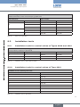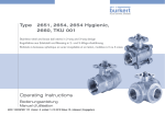
1
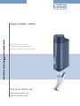
Type3360, 3361 Electromotive control valve Elektromotorisches Regelventil Vanne de régulation électromotorisée Service Manual Serviceanleitung Service Manuel We reserve the right to make technical changes without notice. Technische Änderungen vorbehalten. Sous réserve de modifications techniques. © 2015 Bürkert Werke GmbH Operating Instructions 1510/00_EUml_00810485 / Original DE Type 3360, 3361 Content 1 The service instructions.....................................................................................................................................................5 1.1 Symbols.......................................................................................................................................................................................5 1.2 Definition of the term "device".........................................................................................................................................5 2 Basic safety instructions..................................................................................................................................................6 3 General information.................................................................................................................................................................8 4 5 3.1 Contact addresses.................................................................................................................................................................8 3.2 Warranty.......................................................................................................................................................................................8 3.3 Information on the Internet................................................................................................................................................8 3.4 Auxiliary materials..................................................................................................................................................................8 Overview of spare parts.......................................................................................................................................................9 4.1 Replacement part sets for Type 3360..........................................................................................................................9 4.2 Replacement part sets for Type 3361..........................................................................................................................9 4.3 Spare parts for Types 3360 and 3361......................................................................................................................10 Changing the control cone set................................................................................................................................11 5.1 Removing the actuator......................................................................................................................................................11 5.1.1 Opening valve electrically..................................................................................................................11 5.1.2 Opening valve mechanically.............................................................................................................13 5.2 Changing the control cone set.....................................................................................................................................15 5.3 Installing the actuator........................................................................................................................................................16 5.4 Running X.TUNE...................................................................................................................................................................17 5.4.1 6 Adjustment using the buttons in the device..................................................................................17 Changing the seal set.........................................................................................................................................................18 6.1 Removing the control cone............................................................................................................................................18 6.2 Changing the packing gland..........................................................................................................................................19 6.2.1 6.3 Changing the packing gland for the connection size 10/15 (DN4-15) and vacuum version....................................................................................................................................21 Installing the control cone..............................................................................................................................................22 3 english Type 3360, 3361 7 Changing the valve set.......................................................................................................................................................23 7.1 8 9 Changing the valve set.....................................................................................................................................................23 Changing the energy pack...............................................................................................................................................25 8.1 Removing the display module or dummy cover.................................................................................................25 8.2 Removing LED and storage module..........................................................................................................................26 8.3 Removing actuator cover.................................................................................................................................................26 8.4 Replacing the SAFEPOS energy-pack.....................................................................................................................26 Accessories, spare parts.................................................................................................................................................28 9.1 Communications software..............................................................................................................................................28 9.1.1 9.2 9.3 USB interface.......................................................................................................................................28 Spare parts..............................................................................................................................................................................29 9.2.1 Spare parts for control valves of Types 3360 and 3361...........................................................29 9.2.2 Spare parts for angle seat control valve of Type 3360..............................................................29 9.2.3 Spare parts for straight seat control valve of Type 3361...........................................................29 Installation tools...................................................................................................................................................................31 9.3.1 Installation tools for control valves of Types 3360 and 3361...................................................31 9.3.2 Installation tools for control valves of Type 3361.........................................................................31 10 Packaging, transport...........................................................................................................................................................32 11 Storage...............................................................................................................................................................................................32 12 Disposal.............................................................................................................................................................................................32 4 english Type 3360, 3361 The service instructions 1 The service instructions The service instructions describe the procedure for changing spare parts of the process valves of Types 3360 and 3361. Keep these instructions in a location which is easily accessible to every user and make these instructions available to every new owner of the device. The service instructions contain important safety information. Failure to observe these instructions may result in hazardous situations. ▶▶The service instructions must be read and understood. 1.1 Symbols Danger! Warns of an immediate danger. ▶▶Failure to observe the warning will result in fatal or serious injuries. Warning! Warns of a potentially dangerous situation. ▶▶Failure to observe the warning may result in serious injuries or death. Caution! Warns of a possible danger. ▶▶Failure to observe this warning may result in a moderate or minor injury. Note! Warns of damage to property! • Failure to observe the warning may result in damage to the device or the equipment. indicates important additional information, tips and recommendations. refers to information in these operating instructions or in other documentation. →→designates a procedure which you must carry out. 1.2 Definition of the term "device" In these instructions, the term "device" always refers to the Types 3360 and 3361. 5 english Type 3360, 3361 Basic safety instructions 2 Basic safety instructions These safety instructions do not make allowance for any • contingencies and events which may arise during the assembly, operation, and maintenance. • local safety regulations – the operator is responsible for observing these regulations, also in relation to the installation personnel. Risk of injury from high pressure. ▶▶Before working on the system or device, switch off the pressure and vent or drain lines. If switched on for a prolonged time, risk of burns or fire due to hot device surface. ▶▶Keep the device away from highly flammable substances and media and do not touch with bare hands. Risk of crushing due to mechanically moving parts. ▶▶Perform installation and maintenance work only in the isolated state. Devices with SAFEPOS energy-pack: Completely drain SAFEPOS energy-pack. Wait until LED illuminated ring goes out; the LED status must not be in LED off mode. ▶▶Keep clear of the openings in the valve body. Danger due to an uncontrolled process in the event of a power failure. If devices do not have the optional SAFEPOS energy-pack, the valve remains in an undefined position in the event of a power failure. ▶▶If the valve position is relevant as regards safety in the event of a power failure: Use only those devices which have the SAFEPOS energy-pack (optional energy pack). ▶▶In the SAFEPOS select a valve position which is safe for the process. General hazardous situations. To prevent injuries: ▶▶Do not make any internal or external changes on the device and do not subject it to mechanical stress. ▶▶Only feed media specified in the data sheet into the media connections. ▶▶Secure to prevent unintentional actuation. ▶▶Only trained technicians may perform installation and maintenance work. ▶▶The valves must be installed in accordance with the regulations applicable in the country. ▶▶After an interruption in the power supply, ensure that the process is restarted in a controlled manner. Observe sequence! 1. Apply supply voltage. 2. Charge the device with medium. ▶▶Observe the general rules of technology. ▶▶Install the valves must in accordance with the regulations applicable in the country. 6 english Type 3360, 3361 Basic safety instructions Note! Electrostatically sensitive components and modules. The device contains electronic components which react sensitively to electrostatic discharge (ESD). Contact with electrostatically charged persons or objects are hazardous to these components. In the worst case scenario, they will be destroyed immediately or will fail after start-up. • Observe the requirements in accordance with EN 61340-5-1 to minimize or avoid the possibility of damage caused by a sudden electrostatic discharge. • Do not touch electronic components while the supply voltage is switched on. 7 english Type 3360, 3361 General information 3 General information 3.1 Contact addresses Germany Bürkert Fluid Control Systems Sales Center Christian-Bürkert-Str. 13-17 D-74653 Ingelfingen Tel. + 49 (0) 7940 - 10 91 111 Fax + 49 (0) 7940 - 10 91 448 Email: [email protected] International Contact addresses can be found on the final pages of the printed operating instructions. And also on the Internet at: www.burkert.com 3.2 Warranty The warranty is only valid if the device is used as intended in accordance with the specified application conditions. 3.3 Information on the Internet Operating instructions and data sheets for Types 3360 and 3361 can be found on the Internet at: www.burkert.com 3.4 Auxiliary materials The following auxiliary materials are recommended in these instructions for carrying out repairs: Type of auxiliary material Auxiliary material Manufacturer's specifications Sealer and anti-seize agents Silicone grease OKS 1110-3 OKS Schmierstoffe GmbH www.oks-germany.com Lubrication paste Klüber paste UH1 96-402 Klüber Lubrication München www.klueber.de 8 english Type 3360, 3361 Overview of spare parts 4 Overview of spare parts 4.1 Replacement part sets for Type 3360 The following replacement part sets are available for Type 3360: • Control cone set consisting of: Graphite seal, control cone, dowel pin and lubricant • Seal set for the packing gland consisting of: Individual parts of the packing gland, graphite seal and lubricant • Spindle guide for the packing gland consisting of: Spindle guide, graphite seal and lubricant 4 1 5 Item Description 1 Graphite seal 2 Control cone 3 Dowel pin 4 Seal set for packing gland 5 Spindle guide for packing gland Control cone set 3 2 4.2 Replacement part sets for Type 3361 The following replacement part sets are available for Type 3361: • Control cone set consisting of: Graphite seal, control cone, dowel pin and lubricant • Valve set consisting of: Graphite seal, control cone, dowel pin, valve seat and lubricant • Seal set for the packing gland consisting of: Individual parts of the packing gland, graphite seal and lubricant • Spindle guide for the packing gland consisting of: Spindle guide, graphite seal and lubricant 9 english Type 3360, 3361 Overview of spare parts Item Description 5 1 2 3 6 1 Graphite seal 2 Control cone 3 Dowel pin 4 Valve seat 5 Seal set for packing gland 6 Spindle guide for packing gland Control cone set Valve set 4 4.3 Spare parts for Types 3360 and 3361 • SAFEPOS energy-pack. Optionally there is an energy pack for the device. If the supply voltage fails, the energy pack supplies the actuator with the required energy to move the valve into the required position which can be adjusted via the menu. SAFEPOS energy-pack 10 english Type 3360, 3361 Changing the control cone set 5 Changing the control cone set Before the control cone set can be changed, the actuator must be removed from the valve body. 5.1 Removing the actuator Danger! Risk of injury from high pressure. ▶▶Before working on the system or device, switch off the pressure and vent or drain lines. Warning! Risk of injury if the wrong tools are used. It is dangerous to use unsuitable tools for installation work as the device may be damaged. ▶▶To remove the actuator from the valve body, use an open-end wrench, never a pipe wrench. When removing the actuator from the valve body, ensure that the valve is in the open position. The valve position must be detected on the mechanical position indicator (as illustrated in "Figure 1"). The control valve can be manually opened in 2 ways: electrically or mechanically. Mechanical position indicator Valve completely open Actuator Actuator base Valve completely closed Body connection Valve body Figure 1: Mechanical position indicator 5.1.1 Opening valve electrically Depending on the device version, the valve is manually and electrically opened on the display or by pressing 2 buttons which are located on the LED and storage module under the dummy cover. Devices with display module The valve is opened on the display in View 1 (start screen) and in MANUAL operating state. You can access View 1 by holding down the Back button. To open and close the valve, the MANU / AUTO layout must be selected for View 1 (preset at the factory). An exact description can be found in the operating instructions at www.burkert.com. 11 english Type 3360, 3361 Changing the control cone set Information bar Symbol for MANUAL operating state POS 70.7 % View 2 CONFIGURATION View 1 of x Open Closed Display: View 1 in MANUAL operating state. Auto Layout: MANU / AUTO Back button Menu button Navigation buttons Figure 2: Electrical manual control on the display →→ Press Menu button: Change to MANUAL operating state. can be seen on the information bar. The 2 arrow symbols labeled "open" and "closed" The HAND symbol are shown. The LED illuminated ring on the device flashes. →→ Press upper navigation button until the valve is completely open. The valve position must be detected on the mechanical position indicator (see "Figure 1"). →→Clamp the valve body into a holding fixture. →→Place a suitable open-end wrench on the body connection. Do not unscrew the body connection with a tool which may damage the body connection. →→Unscrew the actuator off the valve body. Devices without display module To actuate the valve, the device must be in MANUAL operating state. The 2 buttons for opening and closing the valve are located under the dummy cover. DIP switches Release dummy cover Operating state MANUAL: DIP 4 ON Figure 3: Setting MANUAL operating state →→Rotate the dummy cover counter-clockwise by 90° and remove from the actuator housing. →→Set DIP switch 4 to ON. The device is the MANUAL operating state. 12 →→Press OPEN button until the valve is completely open. The valve position must be detected on the mechanical position indicator (see "Figure 1"). english Type 3360, 3361 Changing the control cone set OPEN button for opening the valve Figure 4: CLOSE button for closing the valve Electrical manual control for devices without display module →→Clamp the valve body into a holding fixture. →→Place a suitable open-end wrench on the body connection. Do not unscrew the body connection with a tool which may damage the body connection. →→Unscrew the actuator off the valve body. 5.1.2 Opening valve mechanically When the supply voltage is not applied, e.g. during installation or in the event of a power failure, the valve can be opened with the mechanical manual control. Note! The mechanical manual control may be used in a de-energized state only, otherwise the device may be damaged. Note! Carefully remove display module ensuring that the connection cable and the HMI interface are not damaged. →→Rotate the display module or dummy cover counter-clockwise by 90° and remove from the actuator housing. On the display module pay attention to the connection cable leading to the HMI interface! Release dummy cover Figure 5: Release display Removing dummy cover or display module from the actuator housing 13 english Type 3360, 3361 Changing the control cone set Note! Damage to the manual control by exceeding the tightening torque. If the tightening torque is exceeded on reaching the valve end position, the mechanical manual control will be damaged. ▶▶Do not exceed the maximum tightening torque of 2 Nm. To adjust the valve, use an Allen key with 4 mm width across flats. The mechanical position indicator must detect when the valve reaches the end positions (see "Figure 1"). →→Applying a gentle pressure, couple the mechanical manual control and simultaneously turn the Allen key counter-clockwise (see "Figure 6"). Maximum tightening torque 2 Nm! Mechanical Manual Control Open valve Turn Close valve Press and rotate Figure 6: Mechanical Manual Control →→After reaching the required valve position, remove the Allen key. The valve position must be detected on the mechanical position indicator (see "Figure 1"). →→Clamp the valve body into a holding fixture. →→Place a suitable open-end wrench on the body connection. Do not unscrew the body connection with a tool which may damage the body connection. →→Unscrew the actuator off the valve body. 14 english Type 3360, 3361 Changing the control cone set 5.2 Changing the control cone set →→Knock out dowel pin using a suitable pin punch (see "Table 1"). Table 1: Spindle diameter [mm] Pin punch Connection size Valve body DN [mm] 10 4 10/15 and 20 14 5 25 to 50 Spindle diameter with reference to DN →→Remove control cone. Graphite seal Spindle Dowel pin Control cone Figure 7: Changing the control cone set Note! Important information for the problem-free and safe functioning of the device: The sealing surface and control contour of the control cone cannot be damaged. →→Attach new control cone to the spindle. →→Align bores of the control cone and spindle. →→Support control cone on the cylindrical part with the help of a prism. →→Put on dowel pin and carefully knock in with a hammer. →→Position the dowel pin in the center of the spindle axis. 15 english Type 3360, 3361 Changing the control cone set 5.3 Installing the actuator When installing the actuator, ensure that the valve is in the open position. →→Replace graphite seal. Straight seat valve Angle seat valve Graphite seal Figure 8: Graphite seal Warning! Danger if unsuitable lubricants are used. Unsuitable lubricant may contaminate the medium. In oxygen applications there is a risk of an explosion. ▶▶Only use approved lubricants for specific applications, such as oxygen applications or analytical applications. →→Grease the external thread of the body connection (e.g. with Klüber paste UH1 96-402 from Klüber). →→Place a suitable open-end wrench on the body connection. Do not screw on the body connection with a tool which may damage the body connection. →→Screw actuator onto the valve body. Observe tightening torque (see "Table 2"). Connection size valve body DN [mm] Tightening torques [Nm] 13/15 45 ±3 20 50 ±3 25 60 ±3 32 40 Table 2: 65 ±3 50 70 ±3 65 100 ±3 Tightening torques for valve body / body connection 16 english Type 3360, 3361 Changing the control cone set 5.4 Running X.TUNE After installing the actuator, run the X.TUNE function. When the X.TUNE function is run, the position controller is adjusted to the physical stroke of the actuating element used. Note! Do not run X.TUNE without a mandatory requirement. It is not necessary to rerun the X.TUNE function already run at the factory unless the valve body has been changed. In this case the position controller must be readjusted to the actuating element. Warning! Danger due to uncontrolled process after running the X.TUNE function. If the X.TUNE is run under medium pressure, the controller will be incorrectly adjusted. This will result in an uncontrolled process. ▶▶Never run the X.TUNE under medium pressure. ▶▶Secure system against unintentional activation. 5.4.1 Adjustment using the buttons in the device The 2 buttons for running the X.TUNE are located under the dummy cover. Release dummy cover CLOSE button OPEN button Figure 9: Adjustment of the position controller using the buttons in the device →→To release the dummy cover, rotate counter-clockwise by 90°. →→Remove actuator housing. Run X.TUNE function: Do not run the X.TUNE unless it is absolutely essential. →→Simultaneously hold down the OPEN and CLOSE buttons for 5 s. The rapidly flashing LEDs indicate that the X.TUNE is running. When X.TUNE is complete, the LEDs have their previous status (continuous light for AUTOMATIC operating state, flashing for MANUAL operating state). english 17 Type 3360, 3361 Changing the seal set 6 Changing the seal set Before the seal set can be replaced, the actuator must be removed from the valve body and the control cone must be removed. Danger! Risk of injury from discharge of medium and release of pressure. It is dangerous to remove a device which is under pressure due to the sudden release of pressure or discharge of medium. ▶▶Before removing a device, switch off the pressure. Deaerate lines. Warning! Risk of injury if the wrong tools are used. It is dangerous to use unsuitable tools for installation work as the device may be damaged. ▶▶To remove the actuator from the valve body, use an open-end wrench, never a pipe wrench. ▶▶To replace the packing gland, use a special installation wrench, modified socket wrench or open-end wrench. ▶▶Observe specified tightening torques. Observe exact description for removing the actuator in chapter "5.1 Removing the actuator". 6.1 Removing the control cone Warning! Risk of crushing due to mechanically moving parts. ▶▶Switch off supply voltage. ▶▶Devices with SAFEPOS energy-pack: Completely drain SAFEPOS energy-pack. Wait until LED illuminated ring goes out; the LED illuminated display must not be in LED off mode. ▶▶Keep clear of the openings in the valve body. →→Knock out dowel pin using a suitable pin punch (see "Table 1"). →→Remove control cone. Note! Important information for the problem-free and safe functioning of the device: The sealing surface and control contour of the control cone must not be damaged. 18 english Type 3360, 3361 Changing the seal set 6.2 Changing the packing gland Warning! Risk of injury from ejected parts. When the spindle opening is exposed, the individual parts of the packing gland are pressed out at an undefined speed when the relief bore is pressurized. ▶▶Before pressurizing with compressed air, safeguard the ambient area of the discharge opening (e.g. place spindle on a firm base). Caution! Not all individual parts of the packing gland are pressed out by pressurizing with compressed air. Usually the upper gaskets remain in the packing gland tube. Replace the pressed out individual parts only. →→Place the open-end wrench on the body connection. Unscrew spindle guide with the aid of a modified socket wrench. Modified socket wrench is not included in the spare part sets. It can be ordered separately. Order number of the modified socket wrench can be found in chapter "9 Accessories, spare parts". If you have any questions, please contact your Bürkert sales office. Relief bore Seal set for packing gland Spindle guide Figure 10: Spindle guide for the packing gland →→Place spindle on a firm base. Note! Individual parts of the packing gland can remain inserted in the threaded part of the packing gland tube. The individual parts are then ready to hand: 1. Before pressurizing the relief bore: Move the spindle with the aid of the mechanical manual control (see chapter "5.1.2") into the upper position. 2. After pressurizing the relief bore: Move the spindle with the aid of the mechanical manual control into the lower position. 19 english Type 3360, 3361 Changing the seal set →→Pressurize relief bore with approx. 6 bar compressed air. Warning! Danger if unsuitable lubricants are used. Unsuitable lubricant may contaminate the medium. In oxygen applications there is a risk of an explosion. ▶▶Only use approved lubricants for specific applications, such as oxygen applications or analytical applications. →→Grease gaskets of the new packing gland package with the supplied lubricant. →→Place the individual parts on the spindle in the prescribed direction and sequence. →→Push packing gland into the packing gland tube. Pushing direction for packing gland parts Upper gaskets Upper pressure ring(s) Pressure spring Lower pressure ring Lower gaskets Spindle diameter 10 mm Figure 11: Spindle diameter 14 mm Seal set for the packing gland →→Grease spindle guide thread with Klüber paste UH1 96-402. →→Screw in spindle guide. Observe tightening torque (see "Table 3"). Spindle diameter [mm] 10 14 Table 3: Spindle guide tightening torques 20 english Connection size Valve body DN [mm] Tightening torques [Nm] 10/15 15 20 25 25 25 32 to 50 60 Type 3360, 3361 Changing the seal set 6.2.1 Changing the packing gland for the connection size 10/15 (DN4-15) and vacuum version Before the packing gland can be changed, the actuator must be removed from the valve body and the control cone must be removed. An exact description for removing the actuator and the control cone can be found in chapters "5.1 Removing the actuator" and "6.1 Removing the control cone". →→Clamp the body connection in a holding device. →→Loosen 4 screws on the actuator base. Actuator housing Actuator base Screws Figure 12: Removing actuator housing from the actuator base →→Remove actuator housing from the actuator base. →→Clamp the actuator base in a holding device. →→Unscrew spindle guide. Example tool for pressing out the packing gland package Individual parts of the packing gland package Figure 13: Pressing out individual parts of the packing gland →→Using a suitable tool (e.g. screwdriver), carefully press out the packing gland package. Do not damage top of guide. 21 english Type 3360, 3361 Changing the seal set Warning! Danger if unsuitable lubricants are used. Unsuitable lubricant may contaminate the medium. In oxygen applications there is a risk of an explosion. ▶▶Only use approved lubricants for specific applications, such as oxygen applications or analytical applications. →→Grease gaskets of the new packing gland package with the supplied lubricant. →→Insert required individual parts of the new packing gland package in the correct sequence (see "Figure 11"). →→Grease spindle guide thread. Screw in spindle guide. Observe tightening torque (see "Table 3"). →→Place actuator base on the actuator housing. →→Tighten 4 screws crosswise. Observe tightening torque of 5 Nm. 6.3 Installing the control cone →→Attach control cone to the spindle. →→Align bores of the control cone and spindle. →→Support control cone on the cylindrical part with the help of a prism. →→Put on dowel pin and carefully knock in with a hammer. →→Position the dowel pin in the center of the spindle axis. →→Grease valve body thread. →→Replace graphite seal. →→Clamp the valve body into a holding fixture. →→Screw actuator into the valve body. Observe tightening torques (see "Table 2"). Observe exact description for installing the actuator in chapter "5.3". 22 english Type 3360, 3361 Changing the valve set 7 Changing the valve set Before the valve set can be changed, the actuator must be removed from the valve body. Observe exact description for removing the valve set in chapter "5.1 Removing the actuator". 7.1 Changing the valve set →→Select a suitable tool insert and screw it into the installation tool. Installation tool is not included in the valve set. It can be ordered separately. Order number of the installation tool can be found in chapter "9 Accessories, spare parts". If you have any questions, please contact your Bürkert sales office. →→Unscrew the valve seat using the installation tool and a wrench. →→Clean the thread and sealing surface in the valve body using compressed air. →→Place the new valve seat on the installation tool. Installation tool Tool insert (according to nominal widths of the seat) Valve seat Figure 14: Replacing the valve seat Warning! Danger if unsuitable lubricants are used. Unsuitable lubricant may contaminate the medium. In oxygen applications there is a risk of an explosion. ▶▶Only use approved lubricants for specific applications, such as oxygen applications or analytical applications. →→Grease the valve seat thread with a lubricant (e.g. with Klüber paste UH1 95-402 from Klüber). →→Manually screw the fitted valve seat into the valve body thread. 23 english Type 3360, 3361 Changing the valve set →→Screw in valve seat tight using torque wrench. Observe tightening torque (see "Table 4"). Screw connection Table 4: Tightening torques Seat DN Connection size valve body DN [mm] Uncoated seats [Nm] Coated seats [Nm] Tolerance [Nm] 4-15 10/15 25 20 +3 20 20 35 28 +3 25 25 50 40 +5 32 32 80 65 +5 40 40 100 85 +8 50 50 120 120 +8 Tightening torques for valve seat installation →→Grease valve body thread. →→Replace graphite seal. →→Clamp the valve body into a holding fixture. →→Screw actuator into the valve body. Observe tightening torques (see "Table 2"). Observe exact description for installing the actuator in chapter "5.3 Installing the actuator". 24 english Type 3360, 3361 Changing the energy pack 8 Changing the energy pack Caution! Risk of injury due to electric shock. ▶▶Before removing the SAFEPOS energy-pack, switch off the supply voltage. ▶▶Completely drain SAFEPOS energy-pack. Wait until the LED illuminated ring goes out; the LED status must not be in LED off mode. Setting the LED mode is described in the operating instructions at www.buerkert.de. The SAFEPOS energy-pack is located in the actuator housing. To replace it, remove the following parts from the actuator: • Display module or dummy cover • LED and storage module • Actuator cover 8.1 Removing the display module or dummy cover Note! Carefully remove display module ensuring that the connection cable and the HMI interface are not damaged. →→Rotate the display module or dummy cover counter-clockwise by 90° and remove from the actuator housing. On the display module pay attention to the connection cable leading to the HMI interface! Release dummy cover Figure 15: Release display module Removing dummy cover or display module from the actuator housing Device version with display module: →→Release the HMI interface and disconnect the connection cable. 25 english Type 3360, 3361 Changing the energy pack 8.2 Removing LED and storage module Fastening screws Metal housing of the LED and storage module Figure 16: Removing LED and storage module →→Remove the 2 fastening screws (hexagon head key, width across flats 3 mm). →→Take hold of the LED and storage module on both sides of the metal housing and lift out. 8.3 Removing actuator cover Fastening screws Actuator cover Figure 17: Removing actuator cover →→Loosen the 4 fastening screws (T25 hexagonal socket round screws). The screws are integrated in the actuator cover to prevent them from falling out. →→Remove actuator cover. 8.4 Replacing the SAFEPOS energy-pack Note! Recommendation: Before removing the SAFEPOS energy-pack, switch off the supply voltage. →→Loosen locking screw (T10 hexagonal socket round screw). →→Completely pull out SAFEPOS energy-pack on the bracket. 26 english Type 3360, 3361 Changing the energy pack SAFEPOS energy-pack Locking screw (T10 hexagonal socket round screw) Figure 18: Removing the SAFEPOS energy-pack →→Take SAFEPOS energy-pack out of the transport packaging. →→Insert SAFEPOS energy-pack into the two guiding grooves and push in all the way. Guiding groove Guiding groove Figure 19: Inserting the SAFEPOS energy-pack →→Tighten locking screw (T10 hexagonal socket round screw). →→Apply supply voltage. 27 english Type 3360, 3361 Accessories, spare parts 9 Accessories, spare parts Caution! Risk of injury and/or damage due to the use of incorrect parts. Incorrect accessories and unsuitable spare parts may cause injuries and damage the device and the surrounding area. ▶▶Use original accessories and original spare parts from Bürkert only. Accessories Order number Connection cable with M12 socket, 8-pole, (length 2 m) 919061 Connection cable with M12 socket, 4-pole, (length 5 m) 918038 USB büS interface set: büS service interface (büS stick + 0.7 m cable with M12 plug) 772551 büS adapter for büS Service interface (M12 to büS Service interface micro USB) 773254 büS cable extensions from M12 plug to M12 socket Connection cable, length 1 m 772404 Connection cable, length 3 m 772405 Connection cable, length 5 m 772406 Connection cable, length 10 m 772407 Bürkert Communicator Information at www.buerkert.com SIM card 919902 Holding device for line connection DN15 to DN20 693770 Holding device for line connection DN25 to DN50 693771 Table 5: Accessories 9.1 Communications software The PC software "Bürkert Communicator" is designed for communication with Bürkert devices. A detailed description of installation and operation of the PC software can be found in the associated operating instructions. Download the software from: www.buerkert.com 9.1.1 USB interface The PC requires a USB interface for communication with the devices, also an adapter with interface driver (see "Table 5: Accessories"). 28 english Type 3360, 3361 Accessories, spare parts 9.2 Spare parts 9.2.1 Spare parts for control valves of Types 3360 and 3361 Spare parts for Types 3360 and 3361 Order number SAFEPOS energy-pack 285 834 Seal set for packing gland Spindle ø10 mm, DN15...DN20 285 685 Spindle ø14 mm, DN25...DN50 285 722 Spindle ø10 mm VA spindle guide for the packing gland Spindle ø14 mm Body DN15 246 577 Body DN20 246 578 Body DN25 246 579 Body DN32 246 583 Body DN40 246 593 Body DN50 246 594 Table 6: Spare parts for Types 3360 and 3361 9.2.2 Spare parts for angle seat control valve of Type 3360 Control cone set for Type 3360 Order number DN Steel/steel PTFE/steel 13/15 170 322 170 315 20 170 323 170 316 25 170 324 170 318 32 226 925 226 941 40 225 423 226 945 50 225 426 226 948 Table 7: Control cone set for Type 3360 9.2.3 Spare parts for straight seat control valve of Type 3361 Control cone set for Type 3361 includes: Control cone, dowel pin, graphite seal Orifice DN [mm] Order number Seat Body Steel/steel PTFE/steel 4 10/15 149 934 – 6 10/15 152 696 – 8 10/15 149 935 149 962 29 english Type 3360, 3361 Accessories, spare parts Control cone set for Type 3361 includes: Control cone, dowel pin, graphite seal Orifice DN [mm] Seat 10 15 20 25 32 40 50 Order number Body Steel/steel PTFE/steel 10/15 149 912 149 963 20 149 914 149 965 15 149 915 149 943 20 149 916 149 944 25 149 917 149 945 20 149 918 149 946 25 149 951 149 947 32 226 951 226 963 25 149 953 149 949 32 226 952 226 964 40 226 954 226 966 32 226 953 226 965 40 226 955 226 967 50 226 957 226 969 40 226 956 226 968 50 226 958 226 970 50 226 959 226 971 Valve set for Type 3361 includes: Valve seat, control cone, dowel pin, graphite seal Orifice DN [mm] Order number Seat Body Steel/steel PTFE/steel 4 10/15 150 011 – 6 10/15 152 695 – 8 10/15 150 012 150 046 10/15 150 013 150 047 20 150 014 150 048 15 150 015 150 049 20 150 016 150 050 25 150 017 150 051 20 150 018 150 052 25 150 019 150 053 32 227 025 227 037 25 150 021 150 055 32 227 026 227 038 40 227 028 227 040 10 15 20 25 30 english Type 3360, 3361 Accessories, spare parts Valve set for Type 3361 includes: Valve seat, control cone, dowel pin, graphite seal Orifice DN [mm] Seat 32 40 50 Order number Body Steel/steel PTFE/steel 32 227 027 227 039 40 227 029 227 041 50 227 031 227 043 40 227 030 227 042 50 227 032 227 044 50 227 033 227 045 Table 8: Valve set for Type 3361 9.3 Installation tools 9.3.1 Installation tools for control valves of Types 3360 and 3361 Modified socket wrench for packing gland (series production status from April 2012) Spindle ø [mm] Body DN Wrench size Order number 10 15 WAF19 683 220 10 20 WAF21 683 222 14 25...50 WAF21 683 223 Table 9: Installation tools for Types 3360 and 3361 9.3.2 Installation tools for control valves of Type 3361 Installation tool for replacing valve seat Orifice valve seat DN Order number 15 652 604 20 652 605 25 652 606 32 652 607 40 652 608 50 652 609 65 655 562 80 655 563 100 655 564 Table 10: Installation tools for Type 3361 31 english Type 3360, 3361 Packaging, transport 10 Packaging, transport Note! Transport damage. Inadequately protected devices may be damaged during transportation. • Protect the device against moisture and dirt in shock-resistant packaging during transportation. • Prevent the temperature from exceeding or dropping below the permitted storage temperature. 11 Storage Note! Incorrect storage may damage the device. • Store the device in a dry and dust-free location! • Storage temperature: -40 to +70 °C. 12 Disposal Note! Damage to the environment caused by parts contaminated with media. • Dispose of the device and packaging in an environmentally friendly manner! • Observe applicable disposal and environmental regulations. Observe the national waste disposal regulations. 32 english www.burkert.com