1
AIR CONDITIONERS
2011
TECHNICAL & SERVICE MANUAL
Model name
PEFY-P200VMHS-E
PEFY-P250VMHS-E
Safety Precautions
Read before installation and performing electrical work
Thoroughly read the following safety precautions prior to installation.
Observe these safety precautions for your safety.
This equipment may have adverse effects on the equipment on the same power supply system.
Contact the local power authority before connecting to the system.
Symbol explanations
WARNING
This symbol indicates that failure to follow the instructions exactly as stated poses the risk of serious injury or death.
CAUTION
This symbol indicates that failure to follow the instructions exactly as stated poses the risk of serious injury or damage to the unit.
Indicates an action that must be avoided.
Indicates important instructions.
Indicates a parts that requires grounding.
Indicates that caution must be taken with rotating parts. (This symbol is on the main unit label.) <Color: Yellow>
Indicates that the parts that are marked with this symbol pose a risk of electric shock. (This symbol is on the main
unit label.) <Color: Yellow>
WARNING
Carefully read the labels affixed to the main unit.
WARNING
Ask your dealer or a qualified technician to install the unit.
Do not make any modifications or alterations to the unit.
Consult your dealer for repair.
Improper installation by the user may result in water leakage, electric shock, or fire.
Improper repair may result in water leakage, electric shock,
or fire.
Properly install the unit on a surface that can withstand its
weight.
Do not touch the heat exchanger fins with bare hands.
Unit installed on an unstable surface may fall and cause injury.
The fins are sharp and pose a risk of cuts.
In the event of a refrigerant leak, thoroughly ventilate the
room.
Only use specified cables. Securely connect each cable so
that the terminals do not carry the weight of the cable.
If gaseous refrigerant leaks out and comes in contact with
an open flame, toxic gases will be generated.
Improperly connected cables may produce heat and start a
fire.
Properly install the unit according to the instructions in the
Installation Manual.
Take appropriate safety measures against wind gusts and
earthquakes to prevent the unit from toppling over.
Improper installation may result in water leakage, electric
shock, or fire.
Improper installation may cause the unit to topple over and
cause injury or damage to the unit.
Have all electrical work performed by an authorized electrician according to the local regulations and the instructions
in this manual. Use a dedicated circuit.
Only use accessories (i.e., air cleaners, humidifiers, electric
heaters) recommended by Mitsubishi Electric.
Insufficient power supply capacity or improper installation
of the unit may result in malfunctions of the unit, electric
shock, or fire.
HWE1016A
i
GB
WARNING
Keep electrical parts away from water.
Consult your dealer or a qualified technician when moving
or reinstalling the unit.
Wet electrical parts pose a risk of electric shock, smoke, or
fire.
Improper installation may result in water leakage, electric
shock, or fire.
Securely attach the control box cover.
After completing the service work, check for a refrigerant
leak.
If the cover is not installed properly, dust or water may infiltrate and pose a risk of electric shock, smoke, or fire.
If leaked refrigerant is exposed to a heat source, such as a
fan heater, stove, or electric grill, toxic gases will be generated.
Only use the type of refrigerant that is indicated on the unit
when installing or relocating the unit.
Infiltration of any other types of refrigerant or air into the unit
may adversely affect the refrigerant cycle and may cause
the pipes to burst or explode.
Do not try to defeat the safety features of the unit.
Forced operation of the pressure switch or the temperature
switch by defeating the safety features for these devices, or
the use of accessories other than the ones that are recommended by Mitsubishi Electric may result in smoke, fire, or
explosion.
When installing the unit in a small space, take appropriate
precautions to prevent leaked refrigerant from reaching the
limiting concentration.
Leaked refrigerant gas will displace oxygen and may cause
oxygen starvation. Consult your dealer before installing the
unit.
Consult your dealer for proper disposal method.
Do not use a leak detection additive.
Precautions for handling units for use with R410A
CAUTION
Do not use the existing refrigerant piping.
Only use R410A.
A large amount of chlorine that may be contained in the residual refrigerant and refrigerator oil in the existing piping
may cause the refrigerator oil in the new unit to deteriorate.
The use of other types of refrigerant that contain chloride
may cause the refrigerator oil to deteriorate.
Use a vacuum pump with a check valve.
Use refrigerant piping materials made of phosphorus deoxidized copper. Keep the inner and outer surfaces of the
pipes clean and free of such contaminants as sulfur, oxides,
dust, dirt, shaving particles, oil, and moisture.
If a vacuum pump that is not equipped with a check valve is
used, the vacuum pump oil may flow into the refrigerant cycle and cause the refrigerator oil to deteriorate.
Contaminants in the refrigerant piping may cause the refrigerator oil to deteriorate.
Prepare tools for exclusive use with R 410A. Do not use the
following tools if they have been used with the conventional
refrigerant: gauge manifold, charging hose, gas leak detector, check valve, refrigerant charge base, vacuum gauge,
and refrigerant recovery equipment.
Store the piping materials indoors, and keep both ends of
the pipes sealed until immediately before brazing. (Keep elbows and other joints wrapped in plastic.)
If the refrigerant or the refrigerator oil that may be left on these
tools are mixed in with R410A, it may cause the refrigerator oil
in the new system to deteriorate.
Infiltration of water may cause the refrigerator oil to deteriorate.
Leak detectors for conventional refrigerants will not detect an
R410A leak because R410A is free of chlorine.
Infiltration of dust, dirt, or water into the refrigerant system
may cause the refrigerator oil to deteriorate or cause the
compressor to malfunction.
Use a small amount of ester oil, ether oil, or alkyl benzene
to coat flares and flanges.
Do not use a charging cylinder.
Infiltration of a large amount of mineral oil may cause the refrigerator oil to deteriorate.
If a charging cylinder is used, the composition of the refrigerant
in the cylinder will change and become unsuitable for use.
Charge the system with refrigerant in the liquid phase.
Exercise special care when handling tools for use with R410A.
If gaseous refrigerant is drawn out of the cylinder first, the
composition of the remaining refrigerant in the cylinder will
change and become unsuitable for use.
HWE1016A
Infiltration of dust, dirt, or water into the refrigerant system
may cause the refrigerator oil to deteriorate.
ii
GB
CONTENTS
[1] Components and Functions...................................................................................................... 1
[2] Specifications............................................................................................................................ 3
[3] Sound pressure levels .............................................................................................................. 5
[4] Fan performance and corrected air flow ................................................................................... 8
[5] Outlines and Dimensions........................................................................................................ 10
[6] Wiring Diagram ....................................................................................................................... 11
[7] Refrigerant system diagram.................................................................................................... 13
[8] Troubleshooting ...................................................................................................................... 14
[9] Disassembly Procedure.......................................................................................................... 61
[10] Optional parts ....................................................................................................................... 68
HWE1016A
GB
HWE1016A
GB
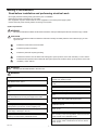
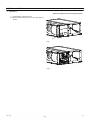
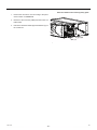
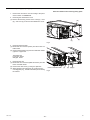
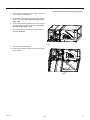
[1] Components and Functions
XI Indoor Unit
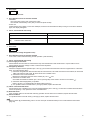
1. Indoor Unit
(1) In case of rear inlet
Air outlet
Air inlet
2. Remote Controller
[PAR-21MAA]
Once the operation mode is selected, the unit will remain in the selected mode until changed.
(1) Remote Controller Buttons
1
2
[Set Temperature] Button
7
[Vane Control] Button
[Timer Menu] Button
8
[Ventilation] Button
[Monitor/Set] Button
[Operation] Button
3 [Mode] Button
9
[Check/Clear] Button
[Back] Button
10 [Test Run] Button
4 [Timer On/Off] Button
11 [Filter] Button
[Set Day] Button
[ ] Button
5 [Louver] Button
12 [ON/OFF] Button
[Operation] Button
13 Position of built-in room thermistor
6 [Fan Speed] Button
14 [Set Time] Button
Keep the remote controller out of direct sunlight to ensure accurate measurement of room temperature.
The thermistor at the lower right-hand section of the remote controller must be free from obstructions to ensure accurate measurement of room temperature.
HWE1016A
-1-
GB
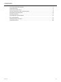
(2) Remote Controller Display
A
Current time/Timer time
I
Louver swing
B
Centralized control indicator
J
Ventilation
C
Timer OFF indicator
K
Filter sign
D
Timer mode indicator
L
Sensor position
E
Operation mode display:
FAN,
HEAT
M
Room temperature
F
Function mode indicator
N
Vane setting
G
Preset temperature
O
Fan speed
H
Power indicator
P
Operation lamp
HWE1016A
COOL,
DRY,
AUTO,
-2-
GB
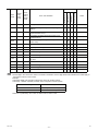
[2] Specifications
1. Specifications
Model
Power supply
Capacity*1
Power consumption
50Pa
100Pa
150Pa
200Pa
250Pa
Current consumption
*2
50Pa
100Pa
150Pa
200Pa
250Pa
External finish
Dimensions
Net weight
Heat exchanger
Fan
Voltage
Frequency
Cooling
Heating
Cooling
Heating
Cooling
Heating
Cooling
Heating
Cooling
Heating
Cooling
Heating
Cooling
Heating
Cooling
Heating
Cooling
Heating
Cooling
Heating
Cooling
Heating
V
Hz
kW
kW
kW
kW
kW
kW
kW
kW
kW
kW
kW
kW
A
A
A
A
A
A
A
A
A
A
Height
Width
Depth
mm
mm
mm
Type
Airflow rate (H-M-L)
Motor
Air filter
Refriferant pipe dimensions
m3/min
External static pressure
Output
Gas (Brazed connection)
Liquid (Brazed connection)
Drain pipe dimensions
Operating noise (H-M-L)
Aux. duct
2m
1.5m
1m
50Pa
100Pa
150Pa
200Pa
250Pa
Pa
kW
mm
[in.]
mm
[in.]
mm
[in.]
dB(A)
PEFY-P200VMHS-E PEFY-P250VMHS-E
1-phase 220-240
50/60
22.4
28.0
25.0
31.5
0.43
0.59
0.52
0.70
0.63
0.82
0.75
0.95
0.89
0.97
2.31
3.08
2.79
3.75
3.32
4.43
3.95
5.10
4.81
5.29
Galvanized
470
1250
1120
97
100
Cross fin (Alminium fin and copper tube)
Sirocco fan x 2
72-61-50
84-71-58
(50)/(100)/150/(200)/(250)
0.87
Option
ø19.05
ø22.2
ø3/4
ø7/8
ø9.52
ø3/8
O.D.32
1-1/4
39-35-32
42-38-35
41-37-34
44-40-37
43-39-36
46-42-39
45-41-38
48-44-41
47-43-40
50-46-43
Measurement location 2
* Measured in anechoic room.
*1 <Cooling> Indoor temperature: 27°CDB/19°CWB (81°FDB/66°FWB) Outdoor temperature: 35°CDB (95°FDB)
<Heating> Indoor temperature: 20°CDB (68°FWB) Outdoor temperature: 7°CDB/6°CWB (45°FDB/43°FWB)
*2 Measured at a power supply voltage of 230 V
HWE1016A
-3-
GB
2. Electrical component specifications
Component
Symbol
Room temperature
thermistor
TH21
Liquid pipe thermistor
TH22
Resistance 0°C/15kΩ, 10°C/9.6kΩ, 20°C/6.3kΩ, 25°C/5.4kΩ, 30°C/4.3kΩ, 40°C/3.0kΩ
Gas pipe thermistor
TH23
Resistance 0°C/15kΩ, 10°C/9.6kΩ, 20°C/6.3kΩ, 25°C/5.4kΩ, 30°C/4.3kΩ, 40°C/3.0kΩ
Fuse (INV board)
F01
250V 15A
Fuse (NF board)
F001
250V 10A
Fuse (NF board)
F100
250V 3.15A
MF
8-pole, Output 870W ERC8801BB
LEV1
LEV2
12VDC Stepping motor drive port diameter ø3.2 (0~2000 pulse)
Fan motor
Linear expansion valve
Power supply terminal
block
HWE1016A
Resistance 0°C/15kΩ, 10°C/9.6kΩ, 20°C/6.3kΩ, 25°C/5.4kΩ, 30°C/4.3kΩ, 40°C/3.0kΩ
TB2
(L, N,
-4-
) 450V 30A
GB
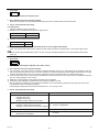
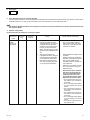
[3] Sound pressure levels
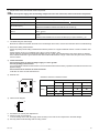
1. Sound pressure level
Ceiling concealed
1m
2m
Outlet
1.5m
Inlet
Measurement point
2. NC curves
PEFY-P200VMHS-E
External Static Pressure:50Pa
Power Source: 220-240V, 50Hz/60Hz
60.0
NC-60
55.0
50.0
NC-50
45.0
40.0
NC-40
35.0
30.0
NC-30
25.0
20.0
15.0
10.0
70.0
High
Middle
Low
65.0
Approximate minimum
audible limit on
continuous noise
63
125
250
500
1k
2k
Octave band center frequencies (Hz)
NC-20
4k
Octave band pressure level (dB) 0dB=20μPa
Octave band pressure level (dB) 0dB=20μPa
70.0
External Static Pressure:100Pa
Power Source: 220-240V, 50Hz/60Hz
External Static Pressure:150Pa
Power Source: 220-240V, 50Hz/60Hz
60.0
50.0
NC-50
45.0
40.0
NC-40
35.0
30.0
NC-30
25.0
15.0
10.0
HWE1016A
NC-60
55.0
20.0
Approximate minimum
audible limit on
continuous noise
63
125
250
500
1k
2k
Octave band center frequencies (Hz)
50.0
NC-50
45.0
40.0
NC-40
35.0
30.0
NC-30
25.0
20.0
15.0
Approximate minimum
audible limit on
continuous noise
63
125
250
500
1k
2k
Octave band center frequencies (Hz)
70.0
High
Middle
Low
65.0
NC-60
55.0
NC-20
4k
8k
External Static Pressure:200Pa
Power Source: 220-240V, 50Hz/60Hz
NC-20
4k
Octave band pressure level (dB) 0dB=20μPa
Octave band pressure level (dB) 0dB=20μPa
70.0
60.0
10.0
8k
High
Middle
Low
65.0
60.0
-5-
NC-60
55.0
50.0
NC-50
45.0
40.0
NC-40
35.0
30.0
NC-30
25.0
20.0
15.0
10.0
8k
High
Middle
Low
65.0
Approximate minimum
audible limit on
continuous noise
63
125
250
500
1k
2k
Octave band center frequencies (Hz)
NC-20
4k
8k
GB
External Static Pressure:250Pa
Power Source: 220-240V, 50Hz/60Hz
Octave band pressure level (dB) 0dB=20μPa
70.0
High
Middle
Low
65.0
60.0
NC-60
55.0
50.0
NC-50
45.0
40.0
NC-40
35.0
30.0
NC-30
25.0
20.0
15.0
10.0
Approximate minimum
audible limit on
continuous noise
63
125
250
500
1k
2k
Octave band center frequencies (Hz)
NC-20
4k
8k
PEFY-P250VMHS-E
External Static Pressure:50Pa
Power Source: 220-240V, 50Hz/60Hz
60.0
NC-60
55.0
50.0
NC-50
45.0
40.0
NC-40
35.0
30.0
NC-30
25.0
20.0
15.0
10.0
70.0
High
Middle
Low
65.0
Approximate minimum
audible limit on
continuous noise
63
125
250
500
1k
2k
Octave band center frequencies (Hz)
NC-20
4k
Octave band pressure level (dB) 0dB=20μPa
Octave band pressure level (dB) 0dB=20μPa
70.0
External Static Pressure:100Pa
Power Source: 220-240V, 50Hz/60Hz
External Static Pressure:150Pa
Power Source: 220-240V, 50Hz/60Hz
60.0
50.0
NC-50
45.0
40.0
NC-40
35.0
30.0
NC-30
25.0
15.0
10.0
HWE1016A
NC-60
55.0
20.0
Approximate minimum
audible limit on
continuous noise
63
125
250
500
1k
2k
Octave band center frequencies (Hz)
50.0
NC-50
45.0
40.0
NC-40
35.0
30.0
NC-30
25.0
20.0
15.0
Approximate minimum
audible limit on
continuous noise
63
125
250
500
1k
2k
Octave band center frequencies (Hz)
70.0
High
Middle
Low
65.0
NC-60
55.0
NC-20
4k
8k
External Static Pressure:200Pa
Power Source: 220-240V, 50Hz/60Hz
NC-20
4k
Octave band pressure level (dB) 0dB=20μPa
Octave band pressure level (dB) 0dB=20μPa
70.0
60.0
10.0
8k
High
Middle
Low
65.0
60.0
-6-
NC-60
55.0
50.0
NC-50
45.0
40.0
NC-40
35.0
30.0
NC-30
25.0
20.0
15.0
10.0
8k
High
Middle
Low
65.0
Approximate minimum
audible limit on
continuous noise
63
125
250
500
1k
2k
Octave band center frequencies (Hz)
NC-20
4k
8k
GB
External Static Pressure:250Pa
Power Source: 220-240V, 50Hz/60Hz
Octave band pressure level (dB) 0dB=20μPa
70.0
60.0
NC-60
55.0
50.0
NC-50
45.0
40.0
NC-40
35.0
30.0
NC-30
25.0
20.0
15.0
10.0
HWE1016A
High
Middle
Low
65.0
Approximate minimum
audible limit on
continuous noise
63
125
250
500
1k
2k
Octave band center frequencies (Hz)
NC-20
4k
8k
-7-
GB
[4] Fan performance and corrected air flow
PEFY-P200VMHS-E
External static pressure :50Pa
Power source:220-240V, 50Hz/60Hz
80
Limit
External static pressure :100Pa
Power source:220-240V, 50Hz/60Hz
130
Limit
High
120
70
High
110
100
Middle
Static pressure (Pa)
Static pressure (Pa)
60
50
40
Low
30
90
Middle
80
70
Low
60
20
50
10
40
0
40
45
50
55
60
65
70
75
30
80
40
45
50
Airflow rate (m /min)
External static pressure :150Pa
Power source:220-240V, 50Hz/60Hz
180
Limit
170
230
High
Limit
220
65
70
75
80
75
80
High
210
200
150
190
140
180
Static pressure (Pa)
Static pressure (Pa)
60
External static pressure :200Pa
Power source:220-240V, 50Hz/60Hz
160
130
Middle
120
110
100
170
Middle
160
150
140
130
120
90
Low
80
110
Low
100
70
60
40
55
Airflow rate (m3/min)
3
90
45
50
55
60
65
70
75
80
80
Airflow rate (m /min)
40
45
50
55
60
65
70
Airflow rate (m3/min)
3
External static pressure :250Pa
Power source:220-240V, 50Hz/60Hz
270
High
Limit
260
250
240
230
Static pressure (Pa)
220
210
200
Middle
190
180
170
160
150
140
Low
130
120
110
100
40
45
50
55
60
65
70
75
80
Airflow rate (m3/min)
HWE1016A
-8-
GB
PEFY-P250VMHS-E
External static pressure :50Pa
Power source:220-240V, 50Hz/60Hz
100
Limit
90
External static pressure :100Pa
Power source:220-240V, 50Hz
140
High
120
80
110
Middle
Static pressure (Pa)
Static pressure (Pa)
70
60
50
Low
40
30
100
Middle
90
80
70
Low
60
20
50
10
40
0
50
55
60
65
70
75
80
85
30
90
50
55
60
Airflow rate (m3/min)
190
Limit
180
240
High
75
80
85
90
85
90
High
Limit
230
220
210
160
200
Static pressure (Pa)
150
Static pressure (Pa)
70
External static pressure :200Pa
Power source:220-240V, 50Hz/60Hz
170
140
Middle
130
120
110
190
180
170
Middle
160
150
140
130
100
120
Low
Low
110
80
100
70
60
50
65
Airflow rate (m3/min)
External static pressure :150Pa
Power source:220-240V, 50Hz/60Hz
90
High
Limit
130
90
55
60
65
70
75
80
85
80
90
Airflow rate (m3/min)
50
55
60
65
70
75
80
Airflow rate (m3/min)
Static pressure (Pa)
External static pressure :250Pa
Power source:220-240V, 50Hz/60Ηz
290
280
270
260
250
240
230
220
210
200
190
180
170
160
150
140
Low
130
120
110
100
50
55
Limit
High
Middle
60
65
70
75
80
85
90
Airflow rate (m3/min)
HWE1016A
-9-
GB
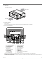
20
1250
1100(Duct)
102
100×10(=1000)
10
24
knockout hole ø27
(Transmission wiring)
knockout hole ø27
(Power souse wiring)
Control box
2×4-ø3 holes
Terminal block
(Transmission)
Terminal block
(Power source)
(100)
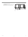
ԘGas pipe
ԙLiquid pipe
Drain hole
(Option)
Terminal block
(MA remocon)
95
422
489
(100)
249
15
29
340(Duct)
ø19.05
ø22.2
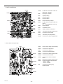
PEFY-P250VMHS-E
ø9.52
105
450
170±5
50
(Actual length)
50
Make the access door
at the appointed position properly
for service maintenance.
Ceiling surface
ԚDrain hose
Access door
450
Drain Piping.
00
㨪2
5
150 55 0
0
Access door
200
㨪3
00
800
Note3
0
135
Note2
730
Required space for service and maintenance.
ԚDrain hose
Drain hose 32mm
<flexible joint>
<accessory>
Note 1.Use M10 screw for the suspension bolt (field supply).
2.Keep the service space for the maintenance from the bottom
ޓޓޓwhen the heat exchanger is cleaned.
3.Keep the service space for the maintenance from the bottom
ޓޓޓwhen the fan motor is changed.
4.Make sure to install the air filter (field supply) on the air intake side.
In case field supplied air filter is used, attach it
ޓޓޓwhere the filter service is easily done.
2×4-ø3 holes
4-14×30 Slot
Suspension bolt hole
ԘGas pipe ԙLiquid pipe
60
PEFY-P200VMHS-E
MODEL
ޓDrain hole
(ޓNormal type)
1067
1120
1124
1034(Suspension bolt pitch)
41
420(Duct)
15
327
10
100
44
164
100
100
100×10(=1000)
50
Air outlet
23
100
50
60 100×3(=300)
1326(Suspension bolt pitch)
2×11-ø3 holes
470
1100(Duct)
100
Air inlet
30
1372
100×3(=300)
- 10 20
More than 20
HWE1016A
More than 20
2×11-ø3 holes
[5] Outlines and Dimensions
Unit: mm
GB
TO MA REMOTE
CONTROLLER
TO OUTDOOR UNIT
BC CONTROLLER
REMOTE CONTROLLER
POWER SUPPLY
ޓAC220㧙240V
ޓ50㨯60Hz
1 1
F001
001
3
TB15
3
2
1
S(SHIELD)
M2
TB5 M1
N
3
1
1
3
DSA
001
(RED)
CNDP
U ZNR
002
(RED)
CNR1
X010
1
NF
5
U ZNR
1
TB2 L
CNACL
CNDB
1 3 5
CNPW2
5
4
CNXB1 3
2
1
X100
3
CNP 1
3
CNFAN 1
3
CNPW1 1
8
3
43
21
P.B.
CNRSP
1234567
CN18V 1
(RED)
CNXC1 CNRSC
12 12345
F100
C016
C015
ZNR
003
U
6
DB01
R
3 1
CN3A
(BLUE)
01
EF 2
SW4
SWA
SW2
SW1
CN25
LED2
LED1
6
4
2
CNINV
1
CNVDC
3
BCD
NF.B.
SW5
3 1
CN15V
901
ON
SW12 SW11
SWC
CNXC2 1 2
I.B.
(GREEN) 2
CNTH 1
5
4
CNCT1 3
2
1
34
CN60 1 2 3 4 5 6
CN44 1 2 3 4
CN4F
ޓCN20
(RED) 1 2
CN41
CNXB2 1 2 3 4 5
1
INV.B.
(BLUE)
CNCT2 2
1
7654321
CNRS2
CN7V 1 2 3 4 5 6
CN32
543
CN100
IPM
1s
10ths
(BRANCH
DIGIT
No. )()ޓ
DIGIT ()
SW14
901
SW3
OFF
8
SWE
CN90
(BLUE)
CN2M
21
F01
78
ACL
345
6 789A
2 2
23
4 56
- 11 23
4 56
HWE1016A
78
CN4F 1 2 3 4
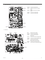
Note 1
ACCT
1 1
2 2
3 3
t°
t°
t°
THHS
TH23
TH22
LEV2
㧹
LEV1
㧹
FS
TH21
Note 1
DP
㧹
㧝㨪
MF
㧹㧿
㧟㨪
WV U
t°
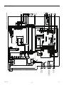
INSIDE SECTION OF CONTROL BOX
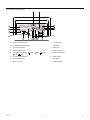
[6] Wiring Diagram
GB
Table.1 SYMBOL EXPLANATION
SYMBOL
I.B.
SYMBOL
NAME
Indoor controller board
P.B.
Power supply board
CN25
Connector
INV.B.
Inverter board
CN32
Connector (Remote switch)
IPM
Intelligent power module
CN41
Connector (HA terminal-A)
F01
Fuse (AC250V 15A)
CN90
Connector (Wireless)
TB2
Power source terminal block
SW1
Switch (for mode selection)
TB5
Transmission terminal block
SW2
Switch (for capacity code)
TB15
Transmission terminal block
SW3
Switch (for mode selection)
TH21
Thermistor (inlet air temp.detection)
SW4
Switch (for model selection)
TH22
Thermistor (piping temp.detection/liquid)
SW5
Switch (for mode selection)
TH23
Thermistor (piping temp.detection/gas)
SW11
Switch (1s digit address set)
THHS
Thermistor (heatsink)
SW12
Switch (10ths digit address set)
SW14
Switch (BRANCH No.)
SWA
Switch (for static pressure selection)
ACL
SWC
Switch (for static pressure selection)
R
SWE
Connector (emergency operation)
DB01
Diode bridge
Noise filter board
ACCT
Current Sensor (AC)
DSA001
Arrester
LED1
LED (Power supply)
ZNR01~
ZNR03
Varistor
LED2
LED (Remote controller supply)
<DP>
Drain pump
<FS>
Float switch
NF.B.
X010,
X100
Aux. relay
F001
Fuse (AC250V 10A)
F100
Fuse (3.15A)
NF
Note
NAME
MF
LEV1, LEV2
Fan motor
Electronic linear expan.valve
AC reactor (Power factor improvement)
Resistor
Inside < > is the optional parts.
Noise filter
1 The part of thin dotted line indicates the circuit for optional parts.
2 To perform a drainage test for the drain pump turn on the SWE on the control board while the indoor unit is being
powerd.
* Be sure to turn off the SWE after completing a drainage test or test run.
3 The wirings to TB2, TB5, TB15 shown in dotted line are field work.
4 Mark
HWE1016A
indicates terminal block,
connector.
- 12 -
GB
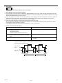
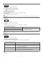
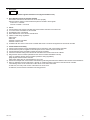
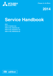
[7] Refrigerant system diagram
(A)
(B)
(G)
(D)
(C)
(H)
(E)
(I)
(A)
Gas pipe thermistor TH23
(B)
Gas pipe
(C)
Liquid pipe
(D)
Brazed connections
(E)
Strainer (#100 mesh)
(F)
Linear expansion valve
(G)
Liquid pipe thermistor TH22
(H)
Heat exchanger
(I)
Room temperature thermistor TH21
HWE1016A
(F)
(E)
- 13 -
GB
[8] Troubleshooting
1. Check methods
1. Component and check points
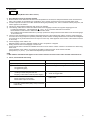
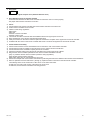
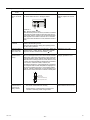
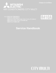
(1) Thermistor
Room temperature thermistor (TH21)
Liquid pipe thermistor (TH22)
Gas pipe thermistor (TH23)
Disconnect the connector and measure the resistance between terminals with a tester.
(Ambient temperature 10°C - 30°C)
Normal
Abnormal
4.3kΩ - 9.6kΩ
Open or short
(Refer to the thermistor characteristic graph below.)
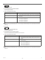
1) Thermistor characteristic graph
Low-temperature thermistor
Room temperature thermistor (TH21)
Liquid pipe thermistor (TH22)
Gas pipe thermistor (TH23)
50
Thermistor R0 = 15 kΩ 3%
Multiplier of B = 3480 kΩ 2%
Rt = 15 exp { 3480(
1 )}
273
15kΩ
9.6kΩ
6.3kΩ
5.2kΩ
4.3kΩ
3.0kΩ
30
(B)
0°C
10°C
20°C
25°C
30°C
40°C
1
273+t
40
20
(A) Temperature
(°C)
(B) Resistance
(kΩ)
10
0
-20
-10
0
10
20
30
40
50
(A)
(2) Fan motor
Refer to the page on "DC fan motor (fan motor/INV board)."(page 48)
(3) Linear expansion valve
Refer to the page on "LEV". ([8] 5)(page 52)
HWE1016A
- 14 -
GB
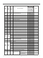
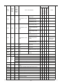
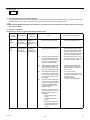
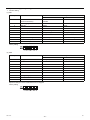
2. Error Code Lists
4300
4305
01
05
(Note)
0900
-
-
Test run
1102
1202
-
Discharge temperature fault
O
1301
-
-
Low pressure fault
O
1302
1402
-
High pressure fault
O
1500
1600
-
Refrigerant overcharge
O
-
1605
-
Preliminary suction pressure fault
O
2500
-
-
Drain sensor submergence
O
2502
-
-
Drain pump fault
O
2503
-
-
Drain sensor (Thd) fault
O
2600
-
-
Water leakage
O
2601
-
-
Water supply cutoff
O
4102
4152
-
Open phase
O
4106
-
-
Transmission power supply fault
O
4109
-
-
Fan operation status detection error
4115
-
-
Power supply signal sync error
4116
-
-
RPM error/Motor error
4220
4225
(Note)
4320
4325
(Note)
Serial communication error
O
O
O
O
[108]
Abnormal bus voltage drop
O
O
[109]
Abnormal bus voltage rise
O
O
[111]
Logic error
O
O
[131]
Low bus voltage at startup
O
-
Heatsink overheat protection
O
4240
4340
-
Overload protection
O
[101]
IPM error
O
O
[104]
Short-circuited IPM/Ground fault
O
O
[105]
Overcurrent error due to short-circuited motor
O
O
[106]
Instantaneous overcurrent (S/W detection)
O
O
[107]
Overcurrent (effective value) (S/W detection)
O
O
[121]
Position detection error at startup
O
[122]
Position detection error during operation
O
4260
5101
HWE1016A
-
1202
-
Heatsink overheat protection at startup
-
Temperature sensor
fault
Return air temperature
(TH21)
OA processing unit inlet
temperature (TH4)
- 15 -
O
O
4330
4335
4350
4355
(Note)
Notes
O
4230
4235
4250
4255
(Note)
LOSSNAY
0403
Error code definition
Indoor unit
Error
(preliminary)
detail
code
Outdoor unit
Error
Code
Preliminary
error
code
Remote controller
Searched unit
O
O
O
O
O
GB
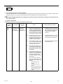
Indoor unit pipe temperature (TH22)
5102
1217
-
Temperature sensor
fault
O
O
Indoor unit gas-side pipe
temperature (TH23)
5103
1205
00
Temperature sensor
fault
O
OA processing unit gasside pipe temperature
(TH3)
Pipe temperature at
heatexchanger outlet
(TH3)
O
O
OA processing unit intake
air temperature (TH1)
5104
1202
-
Temperature sensor
fault
O
Outside temperature
(TH24)
Outdoor unit discharge
temperature (TH4)
O
1204
-
Temperature sensor
fault
Accumulator inlet temperature (TH5)
O
5106
1216
-
Temperature sensor
fault
HIC circuit outlet temperature (TH6)
O
5107
1221
-
Temperature sensor
fault
Outside temperature (TH7)
O
5110
1214
01
Temperature sensor
fault
Heatsink temperature
(THHS)
O
5201
-
-
4300
4305
Detectable
only by the AllFresh type indoor units
O
5105
5301
5305
O
High-pressure sensor fault (63HS1)
O
[115]
ACCT sensor fault
O
[117]
ACCT sensor circuit fault
O
O
[119]
Open-circuited IPM/Loose ACCT connector
O
O
[120]
Faulty ACCT wiring
O
5701
-
-
Loose float switch connector
6201
-
-
Remote controller board fault (nonvolatile memory
error)
O
6202
-
-
Remote controller board fault (clock IC error)
O
6600
-
-
Address overlap
6601
-
-
Polarity setting error
6602
-
-
Transmission processor hardware error
O
O
O
O
6603
-
-
Transmission line bus busy error
O
O
O
O
6606
-
-
Communication error between device and transmission processors
O
O
O
O
6607
-
-
No ACK error
O
O
O
O
HWE1016A
Notes
O
OA processing unit pipe
temperature (TH2)
HIC bypass circuit outlet
temperature (TH2)
Remote controller
Error code definition
LOSSNAY
Error
(preliminary)
detail
code
Indoor unit
Error
Code
Preliminary
error
code
Outdoor unit
Searched unit
O
O
O
O
O
O
- 16 -
GB
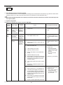
Searched unit
-
No response error
6831
-
-
MA controller signal reception error (No signal reception)
O
O
6832
-
-
MA remote controller signal transmission error
(Synchronization error)
O
O
6833
-
-
MA remote controller signal transmission error
(Hardware error)
O
O
6834
-
-
MA controller signal reception error (Start bit detection error)
O
O
7100
-
-
Total capacity error
O
7101
-
-
Capacity code setting error
O
7102
-
-
Wrong number of connected units
O
7105
-
-
Address setting error
O
7106
-
-
Attribute setting error
7110
-
-
Connection information signal transmission/reception error
7111
-
-
Remote controller sensor fault
7113
-
-
Function setting error
O
7117
-
-
Model setting error
O
7130
-
-
Incompatible unit combination
O
Remote controller
-
LOSSNAY
6608
Error code definition
Indoor unit
Error
(preliminary)
detail
code
Outdoor unit
Error
Code
Preliminary
error
code
O
O
O
O
O
Notes
O
O
O
O
O
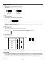
The last digit in the check error codes in the 4000's and 5000's and two-digit detail codes indicate if the codes apply to
compressor inverter on fan inverter.
Example
Code 4225 (detail code 108): Bus voltage drop in the fan inverter system
Code 4230 : Heatsink overheat protection in the compressor inverter system
The last digit
Inverter system
0 or 1
Compressor inverter system
5
Fan inverter system
There are no preliminary error codes or detail codes for indoor units.
XII
HWE1016A
- 17 -
GB
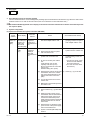
1. Error Code
0403
Serial communication error (Indoor unit)
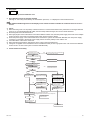
2. Error definition and error detection method
Serial communication cannot be established between the Indoor controller board and the INV board.
3. Cause, check method and remedy
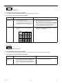
(1) Faulty wiring
Check the following wiring connections.
1) Between Indoor controller board and Power supply board
Indoor controller board Power supply board
CN100
CNRSC
2) Between Power supply board and INV board
Power supply board INV board
CNRSP
CNRS2
(2) INV board failure or Indoor controller board failure or Power supply board failure
If the error persists after a power reset, replace the INV board, the Indoor controller board, or the Power supply board.
Refer to section [8] Troubleshooting, item 4. DC fan motor (fan motor/INV board) for error codes related to the inverter.
(page 48)
1. Error Code
2500
Drain sensor submergence (Models with a drain sensor)
2. Error definition and error detection method
1) If an immersion of the drain sensor in the water is detected while the unit is in any mode other than the Cool/Dry mode and
when the drain pump goes from OFF to ON, this condition is considered preliminary water leakage. While this error is being
detected, humidifier output cannot be turned on.(Applicable to the units manufactured in or after October 2006)
2) If the immersion of the sensor in the water is detected four consecutive times at an hour interval, this is considered water leakage, and "2500" appears on the monitor.
3) Detection of water leakage is also performed while the unit is stopped.
4) Preliminary water leakage is cancelled when the following conditions are met:
One hour after the preliminary water leakage was detected, it is not detected that the drain pump goes from OFF to ON.
The operation mode is changed to Cool/Dry.
The liquid pipe temperature minus the inlet temperature is -10°C [-18°F] or less.
3. Cause, check method and remedy
Cause
Check method and remedy
(1)
Drain water drainage problem
Clogged drain pump
Clogged drain piping
Backflow of drain water from other units
(2)
Adhesion of water drops to the drain sensor
Trickling of water along the lead wire
Rippling of drain water caused by filter clogging
Check for proper drainage.
1)
Check for proper lead wire installation.
2)
Check for clogged filter.
(3)
Failure of the relay circuit for the solenoid valve
Replace the relay.
(4)
Indoor controller board failure
Drain sensor circuit failure
If the above item checks out OK, replace the indoor controller board.
HWE1016A
- 18 -
GB
1. Error Code
2500
Drain sensor submergence (Models with a float switch)
2. Error definition and error detection method
1) If an immersion of the float switch in the water is detected while the unit is in any mode other than the Cool/Dry mode and
when the drain pump goes from OFF to ON, this condition is considered preliminary water leakage. While this error is being
detected, humidifier output cannot be turned on.
2) If the drain pump turns on within one hour after preliminary water leakage is detected and the above-mentioned condition is
detected two consecutive times, water leakage error water leakage is detected, and "2500" appears on the monitor.
3) Detection of water leakage is also performed while the unit is stopped.
4) Preliminary water leakage is cancelled when the following conditions are met:
One hour after the preliminary water leakage was detected, it is not detected that the drain pump goes from OFF to ON.
The operation mode is changed to Cool/Dry.
The liquid pipe temperature minus the inlet temperature is - 10°C [ -18°F] or less.
3. Cause, check method and remedy
Cause
Check method and remedy
(1)
Drain water drainage problem
Clogged drain pump
Clogged drain piping
Backflow of drain water from other units
Check for proper drainage.
(2)
Stuck float switch
Check for slime in the moving parts of the float
switch.
Check for normal operation of the float switch.
(3)
Float switch failure
Check the resistance with the float switch turned on and
turned off.
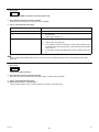
<Reference>
Drain pump operation triggered by a submergence of the liquid level sensor
(except during the Cooing/Dry mode)
6 minutes
Drain pump
output
6 minutes
ON
OFF
ON
Float switch
OFF
input
15
seconds
15
seconds
15
seconds
Submergence of
Sensor in the air
the sensor
Preliminary water leakage
Within 1-hour period
HWE1016A
- 19 -
Submergence of
the sensor
15
seconds
Sensor in the air
15
seconds
Submergence of
the sensor
Water leakage
Within 1-hour period
GB
1. Error Code
2502
Drain pump fault (Models with a drain sensor)
2. Error definition and error detection method
1) Make the drain sensor thermistor self-heat. If the temperature rise is small, it is interpreted that the sensor is immersed in
water. This condition is considered to be a preliminary error, and the unit goes into the 3-minute restart delay mode.
2) If another episode of the above condition is detected during the preliminary error, this is considered a drain pump error, and
"2502" appears on the monitor.
3) This error is always detected while the drain pump is in operation.
4) The following criteria are met when the criteria for the forced stoppage of outdoor unit (system stoppage) are met.
∗"Liquid pipe temperature - inlet temperature
-10°C [ -18 °F] " has been detected for 30 minutes.
∗The immersion of drain sensor is detected 10 consecutive times.
∗The conditions that are listed under items 1) through 3) above are always met before the criteria for the forced stoppage
of the outdoor unit.
5) The indoor unit that detected the conditions that are listed in item 4) above brings the outdoor unit in the same refrigerant
circuit to an error stop (compressor operation prohibited), and the outdoor unit brings all the indoor units in the same refrigerant
circuit that are in any mode other than Fan or Stop to an error stop. "2502" appears on the monitor of the units that came to
an error stop.
6) Forced stoppage of the outdoor unit
Detection timing: The error is detected whether the unit is in operation or stopped.
7) Ending criteria for the forced stoppage of outdoor unit
Power reset the indoor unit that was identified as the error source and the outdoor unit that is connected to the same refrigerant circuit.
Forced stoppage of the outdoor unit cannot be cancelled by stopping the unit via the remote controller.
(Note) Items 1) - 3) and 4) - 7) are detected independently from each other.
The address and attribute that appear on the remote controller are those of the indoor unit that caused the error.
3. Cause, check method and remedy
Cause
Check method and remedy
(1)
Drain pump failure
Check for proper functioning of the drain pump.
(2)
Drain water drainage problem
Clogged drain pump
Clogged drain piping
Check for proper drainage.
(3)
Adhesion of water drops to the drain sensor
Trickling of water along the lead wire
Rippling of drain water caused by filter clogging
1)
Check for proper lead wire installation.
2)
Check for clogged filter.
(4)
Indoor controller board failure
Drain pump drive circuit failure
Drain heater output circuit failure
If the above item checks out OK, replace the indoor controller board.
(5)
Items (1) through (4) above and an indoor unit electronic valve closure failure (leaky valve) occurred simultaneously.
Check the solenoid valves on the indoor unit for leaks.
HWE1016A
- 20 -
GB
1. Error Code
2502
Drain pump fault (Models with a float switch)
2. Error definition and error detection method
1) The immersion of sensor tip in water is detected by the ON/OFF signal from the float switch.
∗Submergence of the sensor
When it is detected that the float switch has been ON for 15 seconds, it is interpreted that the sensor tip is immersed in
water.
∗Sensor in the air
When it is detected that the float switch has been OFF for 15 seconds, it is interpreted that the sensor tip is not immersed
in water.
2) If it is detected that the float switch has been ON for 3 minutes after the immersion of the sensor tip was detected, this is considered a drain pump failure, and "2502" appears on the monitor.
∗The total time it takes for this error to be detected is 3 minutes and 15 seconds, including the time it takes for the first immersion of the sensor tip to be detected.
3) Detection of drain pump failure is performed while the unit is stopped.
4) The following criteria are met when the criteria for the forced stoppage of outdoor unit (system stoppage) are met.
∗"Liquid pipe temperature - inlet temperature
- 10°C [ -18°F] " has been detected for 30 minutes.
∗It is detected by the float switch that the sensor tip has been immersed in water for 15 minutes or more.
∗The conditions that are listed under items 1) through 3) above are always met before the criteria for the forced stoppage
of the outdoor unit.
5) The indoor unit that detected the conditions that are listed in item 4) above brings the outdoor unit in the same refrigerant
circuit to an error stop (compressor operation prohibited), and the outdoor unit brings all the indoor units in the same refrigerant
circuit that are in any mode other than Fan or Stop to an error stop.
6) Forced stoppage of the outdoor unit
Detection timing: The error is detected whether the unit is in operation or stopped.
This error is detected whether the unit is in operation or stopped.
7) Ending criteria for the forced stoppage of outdoor unit
Power reset the indoor unit that was identified as the error source and the outdoor unit that is connected to the same refrigerant circuit.
Forced stoppage of the outdoor unit cannot be cancelled by stopping the unit via the remote controller.
(Note) Items 1) - 3) and 4) - 7) are detected independently from each other.
The address and attribute that appear on the remote controller are those of the indoor unit that caused the error.
3. Cause, check method and remedy
Cause
Check method and remedy
(1)
Drain pump failure
Check for proper functioning of the drain pump
mechanism
(2)
Drain water drainage problem
Clogged drain pump
Clogged drain piping
Check for proper drainage.
(3)
Stuck float switch
Check for slime in the moving parts of the float switch.
Check for normal operation of the float switch.
(4)
Float switch failure
Check the resistance with the float switch turned
on and turned off.
(5)
Indoor controller board failure
Drain pump drive circuit failure
Float switch input circuit failure
Replace indoor controller board.
(6)
Items (1) through (5) above and an indoor unit electronic
valve closure failure (leaky valve) occurred simultaneously.
Check the solenoid valves on the indoor unit for
leaks.
HWE1016A
- 21 -
GB
1. Error Code
2503
Drain sensor (Thd) fault
2. Error definition and error detection method
If the open or short circuit of the thermistor has been detected for 30 seconds, this condition is considered to be a preliminary
error, and the unit goes into the 3-minute restart delay mode.
If another episode of the above condition is detected during the preliminary error, this is considered a drain sensor error.(If
the short or open circuit of the thermistor is no longer detected, normal operation will be restored in 3 minutes.)
This error is detected when one of the following conditions are met.
∗During Cool/Dry operation
∗Liquid pipe temperature minus inlet temperature is equal to or smaller than - 10°C [ -18°F] (except during the defrost cycle)
∗When the liquid temperature thermistor or suction temperature thermistor or short or open circuited.
∗Drain pump is in operation.
∗One hour has elapsed since the drain sensor went off.
Short: 90°C [194 °F] or above
Open: - 20°C [-4 °F] or below
3. Cause, check method and remedy
Cause
Check method and remedy
(1)
Faulty connector (CN31) insertion.
1)
Check for connector connection failure.
Reinsert the connector, restart the operation, and check for
proper operation.
(2)
Broken or semi-broken thermistor wire
2)
Check for a broken thermistor wire.
(3)
Thermistor failure
3)
Check the resistance of the thermistor.
0°C[32 °F]:6.0k
10°C[50 °F]:3.9k
20°C[68°F]:2.6k
30°C[86°F]:1.8k
40°C[104 °F]:1.3k
(4)
Indoor controller board (error detection circuit)
failure
4)
Replace the indoor controller board if the problem recurs
when the unit is operated with the No.-1 and No.-2 pins on
the drain sensor connector (CN31) being short-circuited.
If the above item checks out OK, there are no problems with
the drain sensor.
Turn off the power and turn it back on.
1. Error Code
4109
Indoor unit fan operation error
2. Error definition and error detection method
1) Connector CN28 has remained open-circuited for 100 consecutive secondsduring operation.
3. Cause, check method and remedy
Cause
Check method and remedy
(1)
Auxiliary relay (X13) fault
The coil or the wiring of the auxiliary relay connected to
CN28 is faulty.
(2)
Connector (CN28) is disconnected.
Check the connector for proper connection.
(3)
Blown fuse
Check the fuse on the control circuit board.
(4)
Motor error (thermistor error inside the motor)
Check the unit fan for proper operation in the test run
mode.
If no problems are found with items 1 through 3 above and
the fan does not operate, replace the motor.
HWE1016A
- 22 -
GB
1. Error Code
4116
RPM error/Motor error
2. Error definition and error detection method
LOSSNAY
∗The motor keep running even if the power is OFF.
∗The thermal overload relay is ON. (Only for the three-phase model)
Indoor unit
If detected less than 180rpm or more than 2000rpm, the indoor unit will restart and keep running for 3 minutes.If detected
again, the display will appear.
3. Cause, check method and remedy
Cause
Check method and remedy
(1)
Board failure
Replace the board.
(2)
Motor malfunction
Check for the motor and the solenoid switch.
(3)
Solenoid switch malfunction
1. Error Code
4225
Abnormal bus voltage drop (Indoor unit)
2. Error definition and error detection method
If Vdc 130V or less is detected during Inverter operation. (S/W detection)
3. Cause, check method and remedy
(1) Power supply environment
Check whether the unit makes an instantaneous stop when the detection result is abnormal or a power failure occurs.
Check whether the power voltage is 198V or above across all phases.
(2) Voltage drop detected
Check the voltage at CNVDC (between pins 1 and 3(+)) on the INV board while the inverter is stopped and if it is less than
220V, check the following items.
1) Check the wiring between TB2 and NF board, NF board and ACL, NF board and inrush current resistor, NF board and
DB01, NF board and INV board, NF board and indoor controller board.
2) Check the inrush current resistance.
Measure the interphase resistance of the resistor (R). 22 Ω
10%
3) Check ACL for broken wires.
Check that the resistance between pins 1 and 3 (housing side) of the CNACL connector is not infinite ( ).
4) Check the diode bridge (DB01) for problem.
Refer to section 5. "Troubleshooting the diode bridge".(page 51)
5) If no problems were found with items 1) through 4) above, replace the NF board.
(3) Indoor controller board failure
Confirm that DC12V is applied to the connector CNXB2 (between pins 4 and 5(+)) on the Indoor controller board while the
inverter is operating. If not, replace the Indoor controller board.
(4) NF board failure
If the unit stops within 10 seconds after resuming operation and the same error is detected, replace the NF board.
(5) INV board failure
If no problems were found with items (1) through (4) above, replace the INV board.
Refer to section [8] Troubleshooting, item 4. DC fan motor (fan motor/INV board) for error codes related to the inverter.
(page 48)
HWE1016A
- 23 -
GB
1. Error Code
4225
Abnormal bus voltage rise (Indoor unit)
2. Error definition and error detection method
If Vdc 425V is detected during inverter operation.
3. Cause, check method and remedy
(1) Different voltage connection
Check the power supply voltage on the power supply terminal block (TB2).
(2) INV board failure
If the problem recurs, replace the INV board.
Refer to section [8] Troubleshooting, item 4. DC fan motor (fan motor/INV board) for error codes related to the inverter.
(page 48)
1. Error Code
4225
Logic error (Indoor unit)
2. Error definition and error detection method
H/W error
If only the H/W error logic circuit operates, and no identifiable error is detected.
3. Cause, Check method and remedy
Cause
(1)
External noise
(2)
INV board failure
Check method and remedy
If the problem recurs when the unit is put into operation, replace the INV board.
Refer to section [8] Troubleshooting, item 4. DC fan motor (fan motor/INV board) for error codes related to the inverter.
(page 48)
1. Error Code
4235
Heatsink overheat protection (Indoor unit)
2. Error definition and error detection method
When the heat sink temperature (THHS) remains at or above 85°C [185°F] is detected.
3. Cause, check method and remedy
Cause
Check method and remedy
(1)
Air passage blockage
Check that the heat sink cooling air passage is not blocked
(2)
Fan motor error
Check the fan motor for proper operation (sound, vibration, and rotation).
If any problems were found, check the items listed in sections 2 [3] and [4].
->Refer to [8] 4.2[3][4].(page 50)
(3)
THHS failure
If the problem persists after resuming operation, replace the THHS sensor.
(4)
INV board fault
If no problems were found with items (1) through (3) and the same error is detected after resuming operation, replace the INV board.
Refer to section [8] Troubleshooting, item 4. DC fan motor (fan motor/INV board) for error codes related to the inverter.
(page 48)
HWE1016A
- 24 -
GB
1. Error Code
4255
IPM error (Indoor unit)
2. Error definition and error detection method
IPM error signal is detected.
3. Cause, check method and remedy
Cause
Check method and remedy
(1)
Power supply environment
Check the power supply voltage.
Check whether the power voltage is 198V or above across all phases.
(2)
Static pressure setting error
Check that the static pressure setting and the design static pressure
are correct.
(3)
Inverter failure or fan motor error 1)
Refer to [8] 4.2.[1].(page 49)
2)
Refer to [8] 4.2.[2].(page 49)
3)
Refer to [8] 4.2.[3].(page 50)
4)
Refer to [8] 4.2.[4].(page 50)
Refer to section [8] Troubleshooting, item 4. DC fan motor (fan motor/INV board) for error codes related to the inverter.
(page 48)
1. Error Code
4255
Instantaneous overcurrent (Indoor unit)
Overcurrent (Indoor unit)
2. Error definition and error detection method
Overcurrent 18 Arms and above is detected by the current sensor.
3. Cause, check method and remedy
Cause
Check method and remedy
(1)
Power supply environment
Check the power supply voltage.
Check whether the power voltage is 198V or above across all
phases.
(2)
Static pressure setting error
Check that the static pressure setting and the design static pressure are correct.
(3)
Inverter failure or fan motor error
1)
Refer to [8] 4.2.[1].(page 49)
2)
Refer to [8] 4.2.[2].(page 49)
3)
Refer to [8] 4.2.[3].(page 50)
4)
Refer to [8] 4.2.[4].(page 50)
Refer to section [8] Troubleshooting, item 4. DC fan motor (fan motor/INV board) for error codes related to the inverter.
(page 48)
HWE1016A
- 25 -
GB
1. Error Code
4255
Short-circuited IPM/Ground fault (Indoor unit)
2. Error definition and error detection method
When IPM/IGBT short damage or grounding on the load side is detected just before starting the inverter.
3. Cause, check method and remedy
Cause
(1)
Ground fault of the fan motor
(2)
Inverter failure
Check method and remedy
Refer to [8] 4.2.[4].(page 50)
1)
Refer to [8] 4.2.[1].(page 49)
2)
Refer to [8] 4.2.[2].(page 49)
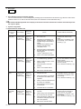
Refer to section [8] Troubleshooting, item 4. DC fan motor (fan motor/INV board) for error codes related to the inverter.
(page 48)
1. Error Code
4255
Overcurrent error due to short-circuited motor (Indoor unit)
2. Error definition and error detection method
When a short is detected on the load side just before starting the inverter operation.
3. Cause, Check method and remedy
Cause
(1)
(2)
Check method and remedy
Short-circuited fan motor coil or inverter failure
Output wiring
1)
Refer to [8] 4.2.[1].(page 49)
2)
Refer to [8] 4.2.[2].(page 49)
3)
Refer to [8] 4.2.[3].(page 50)
Check for a short circuit
Refer to section [8] Troubleshooting, item 4. DC fan motor (fan motor/INV board) for error codes related to the inverter.
(page 48)
HWE1016A
- 26 -
GB
1. Error Code
4255
Position detection error at startup (Indoor unit)
2. Error definition and error detection method
Position error is detected by the hall sensor at inverter startup.
3. Cause, Check method and remedy
Cause
(1)
Loose connector
(2)
Inverter failure or fan motor error
Check method and remedy
Check the CNCT1 and CNINV connectors on the
INV board for proper connection.
1)
Refer to [8] 4.2.[2].(page 49)
2)
Refer to [8] 4.2.[3].(page 50)
Refer to section [8] Troubleshooting, item 4. DC fan motor (fan motor/INV board) for error codes related to the inverter.
(page 48)
1. Error Code
4255
Position detection error during operation (Indoor unit)
2. Error definition and error detection method
Position error is detected by the hall sensor during operation.
3. Cause, Check method and remedy
Cause
(1)
Loose connector
(2)
Inverter failure or fan motor error
Check method and remedy
Check the CNCT1 and CNINV connectors on the
INV board for proper connection.
1)
Refer to [8] 4.2.[2].(page 49)
2)
Refer to [8] 4.2.[3].(page 50)
Refer to section [8] Troubleshooting, item 4. DC fan motor (fan motor/INV board) for error codes related to the inverter.
(page 48)
HWE1016A
- 27 -
GB
1. Error Code
5101
Return air temperature sensor (TH21) fault (Indoor unit)
Return air temperature sensor (TH4) fault (OA processing unit)
5102
Pipe temperature sensor (TH22) fault (Indoor unit)
Pipe temperature sensor (TH2) fault (OA processing unit)
5103
Gas-side pipe temperature sensor (TH23) fault (Indoor unit)
Gas-side pipe temperature sensor (TH3) fault (OA processing unit)
5104
Intake air temperature sensor (TH1) fault (OA processing unit)
Intake air temperature sensor (TH24) fault (All-fresh (100% outdoor air) type indoor unit)
2. Error definition and error detection method
If a short or an open is detected during thermostat ON, the outdoor unit turns to anti-restart mode for 3 minutes. When the
error is not restored after 3 minutes (if restored, the outdoor unit runs normally), the outdoor unit makes an error stop.
Short: detectable at 90°C [194°F] or higher
Open: detectable at -40°C [-40°F] or lower
Sensor error at gas-side cannot be detected under the following conditions.
∗During heating operation
∗During cooling operation for 3 minutes after the compressor turns on.
3. Cause, check method and remedy
Cause
(1)
Thermistor failure
(2)
Connector contact failure
(3)
Disconnected wire or partial disconnected
thermistor wire
(4)
Unattached thermistor or contact failure
(5)
Indoor board (detection circuit) failure
HWE1016A
Check method and remedy
Check the thermistor resistor.
0°C [32°F]: 15 kohm
10°C [50°F]: 9.7 kohm
20°C [68°F] : 6.4 kohm
30°C [86°F] : 4.3 kohm
40°C [104°F] : 3.1 kohm
Check the connector contact.
When no fault is found, the indoor board is a failure.
- 28 -
GB
1. Error Code
5110
Heatsink temperature sensor (THHS) fault (Indoor unit)
2. Error definition and error detection method
When a short or an open of THHS is detected just before or during the inverter operation.
3. Cause, check method and remedy
Cause
Check method and remedy
(1)
Loose connector
Check the CNTH on the INV board for proper connection.
(2)
THHS sensor fault
If the problem persists after resuming operation, replace the THHS sensor.
(3)
INV board failure
If no problems were found with items (1) and (2) above and the problem persists after resuming operation, replace the INV board.
Refer to section [8] Troubleshooting, item 4. DC fan motor (fan motor/INV board) for error codes related to the inverter.
(page 48)
1. Error Code
5305
ACCT sensor circuit fault (Indoor unit)
2. Error definition and error detection method
When abnormal value is detected by the ACCT detection circuit immediately before the inverter starts
3. Cause, check method and remedy
Cause
Check method and remedy
(1)
INV board failure
Refer to [8] 4.2.[1].(page 49)
(2)
Fan motor error
Refer to [8] 4.2.[4].(page 50)
Refer to section [8] Troubleshooting, item 4. DC fan motor (fan motor/INV board) for error codes related to the inverter.
(page 48)
HWE1016A
- 29 -
GB
1. Error Code
5305
Open-circuited IPM/Loose ACCT connector (Indoor unit)
2. Error definition and error detection method
ACCT sensor detected that not enough current is available.
3. Cause, check method and remedy
Cause
Check method and remedy
(1)
Disconnected ACCT sensor
Check CNCT2 on the INV board for proper connection.
(2)
ACCT sensor fault
Disconnect the CNCT2 connector, and check the resistance between
the terminals.
Refer to [8] 4.4.(page 51)
(3)
Inverter failure or fan motor error
1)
Refer to [8] 4.2.[2].(page 49)
2)
Refer to [8] 4.2.[4].(page 50)
3)
If no problems were found with items 1) and 2) above and the problem persists after resuming operation, replace the INV board and the
ACCT sensor.
4)
If the problem persists after taking step 3) above, replace the fan motor.
Refer to section [8] Troubleshooting, item 4. DC fan motor (fan motor/INV board) for error codes related to the inverter.
(page 48)
1. Error Code
5701
Loose float switch connector
2. Error definition and error detection method
Detection of the disconnected float switch (open-phase condition) during operation
3. Cause, check method and remedy
(1) CN4F disconnection or contact failure
Check for disconnection of the connector (CN4F) on the indoor controller board.
HWE1016A
- 30 -
GB
1. Error Code
6600
Address overlap
2. Error definition and error detection method
An error in which signals from more than one indoor units with the same address are received
The address and attribute that appear on the remote controller indicate the controller that detected the error.
3. Cause, check method and remedy
Cause
Check method and remedy
(1)
Two or more of the following have the same address:
Outdoor units, indoor units, LOSSNAY units, controllers such as ME remote controllers.
<Example>
6600 "01" appears on the remote controller
Unit #01 detected the error.
Two or more units in the system have 01 as their address.
(2)
Signals are distorted by the noise on the transmission
line.
HWE1016A
- 31 -
Find the unit that has the same address as that of the error
source.Once the unit is found, correct the address.
Then, turn off the outdoor units, indoor units, and
LOSSNAY units, keep them all turned off for at least
five minutes, and turn them back on.
When air conditioning units are operating normally despite
the address overlap error
Check the transmission wave shape and noise on the
transmission line.
Refer to the service handbook that came with the outdoor
unit.
GB
1. Error Code
6602
Transmission processor hardware error
2. Error definition and error detection method
Although "0" was surely transmitted by the transmission processor, "1" is displayed on the transmission line.
The address/attribute appeared on the display on the remote controller indicates the controller where an error occurred.
3. Cause
1) When the wiring work of or the polarity of either the indoor or outdoor transmission line is performed or is changed while the
power is on, the transmitted data will collide, the wave shape will be changed, and an error will be detected.
2) Grounding fault of the transmission line
3) When grouping the indoor units that are connected to different outdoor units, the male power supply connectors on the multiple
outdoor units are connected to the female power supply switch connector (CN40).
4) When the power supply unit for transmission lines is used in the system connected with MELANS, the male power supply
connector is connected to the female power supply switch connector (CN40) on the outdoor unit.
5) Controller failure of the source of the error
6) When the transmission data is changed due to the noise on the transmission line
7) Voltage is not applied on the transmission line for centralized control (in case of grouped indoor units connected to different
outdoor units or in case of the system connected with MELANS)
4. Check method and remedy
YES
Is the transmission line work
performed while the power is on?
Turn off the power source of outdoor/indoor
units, and turn them on again.
NO
Check the power source of the indoor unit.
NO
198 / 264V?
Faulty power source work
YES
Check the transmission line work is performed
and the shielded wire is treated properly.
Grounding fault or does the shielded
wire contact with the transmission line?
YES
Improper transmission line work
NO
System ?
Single-outdoor-unit system
Multiple-outdoor-unit system
System with the power supply
unit for transmission lines
Confirm that the power supply
connector on the outdoor
unit is not plugged into CN40.
Confirm that the power supply
connector on the outdoor
unit is not plugged into CN40.
Is the male power supply connector
connected to the female power supply
switch connector (CN40) on only one
of the outdoor unit?
YES
NO
Tightly reconnect the male power
supply connector to the female
power supply switch connector (CN40).
Investigation into the
transmission line noise
Noise exist?
NO
Is the male power supply connector
connected to the female power supply
switch connector (CN40) ?
YES
Disconnect the male
power supply on
CN40 and connect it to CN41
*For the investigation method, follow
<Investigation method of transmission wave shape/noise>
YES
Investigation into the
cause of the noise
NO
Controller failure of the
source of the error
Correct the error.
HWE1016A
- 32 -
GB
1. Error Code
6603
Transmission line bus busy error
2. Error definition and error detection method
Generated error when the command cannot be transmitted for 4-10 minutes in a row due to bus-busy
Generated error when the command cannot be transmitted to the transmission line for 4-10 minutes in a row due to noise
The address/attribute appeared on the display on the remote controller indicates the controller where an error occurred.
3. Cause, check method and remedy
Cause
Check method and remedy
(1)
The transmission processor cannot be transmitted as the short-wavelength voltage like noise exists consecutively on the transmission line.
(2)
Error source controller failure
Check the transmission wave shape and noise on the
transmission line.
Refer to the service handbook that came with the outdoor
unit.
-> No noise indicates that the error source controller is a
failure.
-> If noise exists, investigate the noise.
1. Error Code
6606
Communication error between device and transmission processors
2. Error definition and error detection method
Communication error between the main microcomputer on the indoor unit board and the microcomputer for transmission
The address/attribute appeared on the display on the remote controller indicates the controller where an error occurred.
3. Cause, check method and remedy
Cause
Check method and remedy
(1)
Data is not properly transmitted due to accidental
erroneous operation of the controller of the error
source.
(2)
Error source controller failure
HWE1016A
- 33 -
Turn off the power source of the outdoor and the indoor
units.(When the power source is turned off separately, the
microcomputer will not be reset, and the error will not be
corrected.)
-> If the same error occurs, the error source controller is
a failure.
GB
1. Error Code
6607
No ACK error
2. Error definition and error detection method
The error is detected when no acknowledgement (ACK signal) is received after the transmission. (eg. When the data is transmitted six times in a row with 30 seconds interval, the error is detected on the transmission side.)
The address/attribute appeared on the display on the remote controller indicates the controller which did not provide
the response (ACK).
3. System configuration
(1) System with one outdoor unit
Error
source address
Outdoor
unit (OC)
Indoor unit
(IC)
LOSSNAY
(LC)
ME remote
controller
(RC)
HWE1016A
Error display
ME remote
controller (RC)
MA remote
controller (MA)
ME remote
controller (RC)
MA remote
controller (MA)
ME remote
controller (RC)
MA remote
controller (MA)
ME remote
controller (RC)
MA remote
controller (MA)
Detection
method
No acknowledgement
(ACK) at IC
transmission to OC
No acknowledgement
(ACK) at RC
transmission to IC
No acknowledgement
(ACK) at IC
transmission to LC
No acknowledgement
(ACK) at IC
transmission to RC
Cause
(1)
Contact failure of transmission
line of OC or IC
(2)
Decrease of transmission line
voltage/signal by exceeding acceptable range of transmission
wiring.
Farthest:200 m [656ft] or less
Remote controller wiring:
10m [32ft] or less
(3)
Erroneous sizing of transmission
line (Not within the range below).
Wire diameter:
1.25mm2 [AWG16] or more
(4)
Indoor unit control board failure
(1)
When IC unit address is changed
or modified during operation.
(2)
Faulty or disconnected IC transmission wiring
(3)
Disconnected IC connector
(CN2M)
(4)
Indoor unit controller failure
(5)
ME remote controller failure
(1)
The power source of LOSSNAY
has been shut off.
(2)
When the address of LOSSNAY
is changed in the middle of the
operation
(3)
Faulty or disconnected transmission wiring of LOSSNAY
(4)
Disconnected connector (CN1)
on LOSSNAY
(5)
Controller failure of LOSSNAY
(1)
Faulty transmission wiring at IC
unit side.
(2)
Faulty wiring of the transmission
line for ME remote controller
(3)
When the address of ME remote
controller is changed in the middle of the operation
(4)
ME remote controller failure
- 34 -
Check method and remedy
Turn off the power source of the
outdoor unit, and turn it on
again.
If the error is accidental, it will
run normally. If not, check the
causes (1) - (4).
Turn off the outdoor/indoor units
for 5 or more minutes, and turn
them on again.
If the error is accidental, they
will run normally.
If not, check the causes (1) - (5).
Turn off the power source of
LOSSNAY and turn it on again.
If the error is accidental, it will
run normally.
If not, check the causes (1) - (5).
Turn off the power source of the
outdoor unit for 5 minutes or
more, and turn it on again.
If the error is accidental, it will
run normally.
If not, check the causes (1) - (4).
GB
1. Error Code
6607
No ACK error
2. Error definition and error detection method
The error is detected when no acknowledgement (ACK signal) is received after the transmission. (eg. When the data is transmitted six times in a row with 30 seconds interval, the error is detected on the transmission side.)
The address/attribute appeared on the display on the remote controller indicates the controller which did not provide
the response (ACK).
3. System configuration
(2) Grouping of units in a system with multiple outdoor units
Error
source
address
Error display
Detection
method
Outdoor
unit
(OC)
ME remote
controller (RC)
MA remote
controller (MA)
No acknowledgement
(ACK) at IC
transmission to
OC
Indoor
unit
(IC)
ME remote
controller (RC)
MA remote
controller (MA)
No acknowledgement
(ACK) at RC
transmission to
IC
Cause
Check method and remedy
Same cause as that for system with one outdoor unit
Same remedy as that for system with one outdoor unit
(1)
Same causes as (1) - (5) for 1)
system with one outdoor unit
Turn off the power sources of
the outdoor and indoor units
for 5 or more minutes, and turn
them on again. If the error is
accidental, the will run normally.If not, check the cause 2).
(2)
Disconnection or short circuit 2)
of the transmission line for
the outdoor unit on the terminal block for centralized control line connection (TB7)
Check the causes of (1) - (5). If
the cause is found, correct it. If
no cause is found, check 3).
(3)
When multiple outdoor units 3)
are connected and the power source of one of the outdoor units has been shut off.
Check the LED displays for
troubleshooting on other remote controllers whether an
error occurs.
(4)
The male power supply connector of the outdoor unit is
not connected to the female
power supply switch connector (CN40).
(5)
The male power supply connectors on 2 or more outdoor
units are connected to the female power supply switch
connector (CN40) for centralized control.
If an error is found,
-> If an error is found, check
the check code definition, and
correct the error.
If no error is found,
-> Indoor unit board failure
If an error occurs, after the
unit runs normally once, the
following causes may be
considered.
Total capacity error
(7100)
Capacity code error
(7101)
Error in the number of
connected units (7102)
Address setting error
(7105)
HWE1016A
- 35 -
GB
1. Error Code
6607
No ACK error
2. Error definition and error detection method
The error is detected when no acknowledgement (ACK signal) is received after the transmission. (eg. When the data is transmitted six times in a row with 30 seconds interval, the error is detected on the transmission side.)
The address/attribute appeared on the display on the remote controller indicates the controller which did not provide
the response (ACK).
3. System configuration
(2) Grouping of units in a system with multiple outdoor units
Error
source
address
LOSSNAY
(LC)
Error display
ME remote
controller (RC)
MA remote
controller (MA)
Detection
method
No acknowledgement
(ACK) at IC
transmission to
LC
Cause
Check method and remedy
(1)
Factors (1) through (5) in the 1)
"Factors in system with one
outdoor unit" (When performing an interlocked operation
of the LOSSNAY unit and the
indoor units that are connected to different outdoor units.)
Turn off the power source of
LOSSNAY for 5 or more minutes, and turn it on again. If the
error is accidental, it will run
normally.If not, check the
cause 2).
(2)
Disconnection or short circuit 2)
of the transmission line for
the outdoor unit on the terminal block for centralized control line connection (TB7)
Check the causes of (1) - (5). If
the cause is found, correct it. If
no cause is found, check 3).
(3)
When multiple outdoor units
are connected and the power
source of one of the outdoor
units has been shut off.
Same cause as that for indoor
unit described in 3)
(4)
The male power supply connector of the outdoor unit is
not connected to the female
power supply switch connector (CN40).
(5)
The male power supply connectors on 2 or more outdoor
units are connected to the female power supply switch
connector (CN40) for centralized control.
3)
If an error occurs, after the
unit runs normally once, the
following causes may be considered.
Total capacity error
(7100)
Capacity code error
(7101)
Error in the number of
connected units (7102)
Address setting error
(7105)
HWE1016A
- 36 -
GB
1. Error Code
6607
No ACK error
2. Error definition and error detection method
The error is detected when no acknowledgement (ACK signal) is received after the transmission. (eg. When the data is transmitted six times in a row with 30 seconds interval, the error is detected on the transmission side.)
The address/attribute appeared on the display on the remote controller indicates the controller which did not provide
the response (ACK).
3. System configuration
(2) Grouping of units in a system with multiple outdoor units
Error
source
address
Error display
ME remote controller
(RC)
ME remote
controller (RC)
MA remote
controller (MA)
Detection
method
No acknowledgement
(ACK) at IC
transmission to
RC
Cause
Check method and remedy
(1)
Same causes as (1) - (4) for
system with one outdoor unit
1)
Turn off the power source of
LOSSNAY for 5 or more minutes, and turn it on again. If the
error is accidental, it will run
normally.If not, check the
cause 2).
(2)
Disconnection or short circuit 2)
of the transmission line for
the outdoor unit on the terminal block for centralized control line connection (TB7)
Check the causes of (1) - (5). If
the cause is found, correct it. If
no cause is found, check 3).
(3)
When multiple outdoor units
are connected and the power
source of one of the outdoor
units has been shut off.
Same cause as that for indoor
unit described in 3)
(4)
The male power supply connector of the outdoor unit is
not connected to the female
power supply switch connector (CN40).
(5)
The male power supply connectors on 2 or more outdoor
units are connected to the female power supply switch
connector (CN40) for centralized control.
3)
If the problem recurs after
normal operation is restored,
the problem is caused by one
of the following factors:
Total capacity error
(7100)
Capacity code setting
error (7101)
Error in the number of
connected units (7102)
Address setting error
(7105)
HWE1016A
- 37 -
GB
1. Error Code
6607
No ACK error
2. Error definition and error detection method
The error is detected when no acknowledgement (ACK signal) is received after the transmission. (eg. When the data is transmitted six times in a row with 30 seconds interval, the error is detected on the transmission side.)
The address/attribute appeared on the display on the remote controller indicates the controller which did not provide
the response (ACK).
3. System configuration
(3) System connected to the system controllers (MELANS)
Error
source
address
Error display
Detection
method
Cause
Check method and remedy
Outdoor
unit
(OC)
ME remote
controller (RC)
System controller (SC)
MA remote
controller (MA)
No acknowledgement
(ACK) at IC
transmission to OC
Same cause as that for system with one
outdoor unit
Same remedy as that for
system with one outdoor
unit
Indoor
unit
(IC)
ME remote
controller (RC)
MA remote
controller (MA)
No acknowledgement
(ACK) at RC
transmission to IC
Same as grouping of units in a system
with multiple outdoor units
Same remedy as that for
grouping of units in a system with multiple outdoor
units
Error occurrence on some IC
Same remedy as that for
system with one outdoor
unit
System control- No acknowl- 1.
ler (SC)
edgement
(ACK) at SC (1)
transmission to IC
2.
HWE1016A
Same cause as that for system with one
outdoor unit
Error occurrence on all IC in the system
with one outdoor unit
1) Check the LED display
for troubleshooting on the
outdoor unit.
(1)
Total capacity error (7100)
(2)
Capacity code error (7101)
(3)
Error in the number of connected units
(7102)
(4)
Address setting error (7105)
(5)
Disconnection or short circuit of the trans- 2) Check (5) - (7) on the left.
mission line for the outdoor unit on the terminal block for centralized control line
connection (TB7)
(6)
Turn off the power source of the outdoor
unit
(7)
Malfunction of electrical system for the
outdoor unit
3.
Error occurrence on all IC
(1)
Same causes as (1) - (7) described in 2.
(2)
The male power supply connectors on 2
or more outdoor units are connected to
the female power supply switch connector
(CN40) for the transmission line for centralized control.
(3)
Disconnection or shutdown of the power
source of the power supply unit for transmission line
(4)
System controller (MELANS) malfunction
- 38 -
If an error is found,
check the check code
definition, and correct
the error.
If no error is found,
check 2).
Check voltage of the
transmission line for centralized control.
20V or more: Check (1)
and (2) on the left.
Less than 20V: Check
(3) on the left.
GB
1. Error Code
6607
No ACK error
2. Error definition and error detection method
The error is detected when no acknowledgement (ACK signal) is received after the transmission. (eg. When the data is transmitted six times in a row with 30 seconds interval, the error is detected on the transmission side.)
The address/attribute appeared on the display on the remote controller indicates the controller which did not provide
the response (ACK).
3. System configuration
(3) System connected to the system controllers (MELANS)
Error
source
address
ME remote controller
(RC)
Error display
Detection
method
ME remote
controller (RC)
System controller (SC)
MA remote
controller (MA)
No acknowledgement
(ACK) at IC
transmission to
RC
System controller
(SC)
No acknowledgement
(ACK) at
MELANS
transmission to
RC
Cause
1.
Check method and remedy
Same as grouping of units in a system with multiple outdoor units
Same remedy as that for
grouping of units in a system
with multiple outdoor units
Error occurrence on some IC
Same remedy as that for
system with one outdoor unit
(1) Same cause as that for system
with one outdoor unit
2.
Error occurrence on all IC in the
system with one outdoor unit
1)
If an error is found, check
the check code definition,
and correct the error.
If no error is found, check
the cause 2).
(1) An error is found by the outdoor
unit.
Total capacity error (7100)
Capacity code error (7101)
Error in the number of connected
units (7102)
Address setting error (7105)
(2) Disconnection or short circuit of the
transmission line for the outdoor
unit on the terminal block for centralized control line connection
(TB7)
Check the LED display for
troubleshooting on the outdoor unit.
2)
Check (2) - (4) on the left.
(3) Turn off the power source of the
outdoor unit
(4) Malfunction of electrical system for
the outdoor unit
3.
Error occurrence on all IC
Check (1) - (4) on the left.
(1) Same causes as (1) - (4) described
in 2.
(2) When the power supply unit for
transmission lines is used and the
male power supply connector is
connected to the female power
supply switch connector (CN40) for
the transmission line for centralized control
(3) Disconnection or shutdown of the
power source of the power supply
unit for transmission line
(4) System controller (MELANS) malfunction
HWE1016A
- 39 -
GB
1. Error Code
6607
No ACK error
2. Error definition and error detection method
The error is detected when no acknowledgement (ACK signal) is received after the transmission. (eg. When the data is transmitted six times in a row with 30 seconds interval, the error is detected on the transmission side.)
The address/attribute appeared on the display on the remote controller indicates the controller which did not provide
the response (ACK).
3. System configuration
(3) System connected to the system controllers (MELANS)
Error
source
address
System
controller
(SC)
HWE1016A
Error display
ME remote
controller
(RC)
MA remote
controller
(MA)
Detection
method
No acknowledgement
(ACK) at IC
transmission to
SC
Cause
1.
Error display on some displays on
ME remote controllers
(1)
Faulty wiring of the transmission
line for ME remote controller
(2)
Disconnection or contact failure of
the transmission connector for ME
remote controller
(3)
ME remote controller failure
2.
Error occurrence on all IC in the
system with one outdoor unit
(1)
An error is found by the outdoor
unit.
Total capacity error (7100)
Capacity code error (7101)
Error in the number of connected
units (7102)
Address setting error (7105)
(2)
Disconnection or short circuit of the
transmission line for the outdoor
unit on the terminal block for centralized control line connection
(TB7)
(3)
Turn off the power source of the
outdoor unit
(4)
Malfunction of electrical system for
the outdoor unit
3.
Error display on all displays on ME
remote controllers
(1)
Same causes as (1) - (4) described
in 2.
(2)
When the power supply unit for
transmission lines is used and the
male power supply connector is
connected to the female power supply switch connector (CN40) for the
transmission line for centralized
control
(3)
Disconnection or shutdown of the
power source of the power supply
unit for transmission line
(4)
System controller (MELANS) malfunction
- 40 -
Check method and remedy
Check (1) - (3) on the left.
1) Check the LED display for
troubleshooting on the outdoor unit.
If an error is found, check
the check code definition,
and correct the error.
If no error is found, check
the cause 2)
2) Check (2) - (4) on the left.
Check (1) - (4) on the left
GB
1. Error Code
6607
No ACK error
2. Error definition and error detection method
The error is detected when no acknowledgement (ACK signal) is received after the transmission. (eg. When the data is transmitted six times in a row with 30 seconds interval, the error is detected on the transmission side.)
The address/attribute appeared on the display on the remote controller indicates the controller which did not provide
the response (ACK).
3. System configuration
(4) Errors that are not limited to a particular system
Error
source address
Address
which
should not
be existed
Error display
Detection
method
-
-
Cause
(1)
Although the address of ME
remote controller has been
changed after the group is set
using ME remote controller,
the indoor unit is keeping the
memory of the previous address. The same symptom will
appear for the registration with
SC.
(2)
Although the address of
LOSSNAY has been changed
after the interlock registration
of LOSSNAY is made using
ME remote controller, the indoor unit is keeping the memory of the previous address.
Check method and remedy
Delete unnecessary information of non-existing address
which some indoor units have.
Use either of the following two
methods for deletion.
1)
Address deletion by ME remote
controller
Delete unnecessary address information using the manual setting function of ME remote
controller. Refer to Outdoor service handbook.
2)
Deletion of connection information of the outdoor unit by the
deleting switch
Note that the above method
will delete all the group settings set via the ME remote
controller and all the interlock settings between LOSSNAY units and indoor units.
Turn off the power source of
the outdoor unit, and wait for
5 minutes.
Turn on the dip switch (SW22) on the outdoor unit control
board.
Turn on the power source of
the outdoor unit, and wait for
5 minutes.
Turn off the power source of
the outdoor unit, and wait for
5 minutes.
Turn off the dip switch (SW22) on the outdoor unit control
board.
Turn on the power source of
the outdoor unit.
HWE1016A
- 41 -
GB
1. Error Code
6608
No response error
2. Error definition and error detection method
When no response command is returned although acknowledgement (ACK) is received after transmission, an error is detected.
When the data is transmitted 10 times in a row with 3 seconds interval, an error is detected on the transmission side.
The address/attribute appeared on the display on the remote controller indicates the controller where an error occurred.
3. Cause
1) The transmission line work is performed while the power is on, the transmitted data will collide, and the wave shape will be
changed.
2) The transmission is sent and received repeatedly due to noise.
3) Decrease of transmission line voltage/signal by exceeding acceptable range of transmission wiring.
Farthest:200m [656ft] or less
Remote controller wiring:12m [39ft] or less
4) The transmission line voltage/signal is decreased due to erroneous sizing of transmission line.
Wire diameter: 1.25mm2[AWG16] or more
4. Check method and remedy
1) When an error occurs during commissioning, turn off the power sources for the outdoor unit, indoor unit, and LOSSNAY for 5
or more minutes, and then turn them on again.
When they return to normal operation, the cause of the error is the transmission line work performed with the power on.
If an error occurs again, check the cause 2).
2) Check 3) and 4) above.
If the cause is found, correct it.
If no cause is found, check 3).
3) Check transmission wave shape/ noise on trans-mission line by following the instructions detailed in the Outdoor service
handbook.
Noise is the most possible cause of the error "6608".
HWE1016A
- 42 -
GB
1. Error Code
6831
MA controller signal reception error (No signal reception)
2. Error definition and error detection method
Communication between the MA remote controller and the indoor unit is not done properly.
No proper data has been received for 3 minutes.
3.
1)
2)
3)
4)
5)
6)
7)
Cause
Contact failure of the remote controller lines of MA remote controller or the indoor unit.
All the remote controllers are set to SUB.
Failure to meet wiring regulations
Wire length
Wire size
Number of remote controllers
Number of indoor units
The remote controller is removed after the installation without turning the power source off.
Noise interference on the remote controller transmission lines
Faulty circuit that is on the indoor board and performs transmission/ reception of the signal from the remote controller
Problems with the circuit on the remote controller that sends or receives the signals from the remote controller
4.
1)
2)
3)
4)
5)
Check method and remedy
Check for disconnected or loose transmission lines for the indoor units or MA remote controllers.
Confirm that the power is supplied to the main power source and the remote controller line.
Confirm that MA remote controller's capacity limit is not exceeded.
Check the sub/main setting of the MA remote controllers.One of them must be set to MAIN.
Diagnose the remote controller (described in the remote controller installation manual).
[OK]: no problems with the remote controller (check the wiring regulations)
[NG]: Replace the MA remote controller.
[6832, 6833, ERC]: Due to noise interference <Go to 6)>
6) Check wave shape/noise on MA remote controller line by following the instructions detailed in the Outdoor service handbook.
7) When no problems are found with items 1) through 6), replace the indoor unit board or the MA remote controller.
The following status can be confirmed on LED1 and 2 on the indoor unit board.
If LED1 is lit, the main power source of the indoor unit is turned on.
If LED2 is lit, the MA remote controller line is being powered.
HWE1016A
- 43 -
GB
1. Error Code
6832
MA remote controller signal transmission error (Synchronization error)
2. Error definition and error detection method
MA remote controller and the indoor unit is not done properly.
Failure to detect opening in the transmission path and unable to send signals
∗Indoor unit : 3 minutes
∗Remote controller : 6 seconds
3.
1)
2)
3)
4)
5)
Cause
Contact failure of the remote controller lines of MA remote controller or the indoor unit
2 or more remote controllers are set to MAIN
Overlapped indoor unit address
Noise interference on the remote controller lines
Failure to meet wiring regulations
Wire length
Wire size
Number of remote controllers
Number of indoor units
6) Problems with the circuit on the remote controller that sends or receives the signals from the remote controller
4.
1)
2)
3)
4)
5)
Check method and remedy
Check for disconnected or loose transmission lines for the indoor units or MA remote controllers.
Confirm that the power is supplied to the main power source and the remote controller line.
Confirm that MA remote controller's capacity limit is not exceeded.
Check the sub/main setting of the MA remote controllers.One of them must be set to MAIN.
Diagnose the remote controller (described in the remote controller installation manual).
[OK]: no problems with the remote controller (check the wiring regulations)
[NG]: Replace the MA remote controller.
[6832, 6833, ERC]: Due to noise interference <Go to 6)>
6) Check wave shape/noise on MA remote controller line by following the instructions detailed in the Outdoor service handbook.
7) When no problems are found with items 1) through 6), replace the indoor unit board or the MA remote controller.
The following status can be confirmed on LED1 and 2 on the indoor unit board.
If LED1 is lit, the main power source of the indoor unit is turned on.
If LED2 is lit, the MA remote controller line is being powered.
HWE1016A
- 44 -
GB
1. Error Code
6833
MA remote controller signal transmission error (Hardware error)
2. Error definition and error detection method
Communication between the MA remote controller and the indoor unit is not done properly.
An error occurs when the transmitted data and the received data differ for 30 times in a row.
3.
1)
2)
3)
4)
5)
Cause
Contact failure of the remote controller lines of MA remote controller or the indoor unit
2 or more remote controllers are set to MAIN
Overlapped indoor unit address
Noise interference on the remote controller lines
Failure to meet wiring regulations
Wire length
Wire size
Number of remote controllers
Number of indoor units
6) Problems with the circuit on the remote controller that sends or receives the signals from the remote controller
4.
1)
2)
3)
4)
5)
Check method and remedy
Check for disconnected or loose transmission lines for the indoor units or MA remote controllers.
Confirm that the power is supplied to the main power source and the remote controller line.
Confirm that MA remote controller's capacity limit is not exceeded.
Check the sub/main setting of the MA remote controllers.One of them must be set to MAIN.
Diagnose the remote controller (described in the remote controller installation manual).
[OK]: no problems with the remote controller (check the wiring regulations)
[NG]: Replace the MA remote controller.
[6832, 6833, ERC]: Due to noise interference <Go to 6)>
6) Check wave shape/noise on MA remote controller line by following the instructions detailed in the Outdoor service handbook.
7) When no problems are found with items 1) through 6), replace the indoor unit board or the MA remote controller.
The following status can be confirmed on LED1 and 2 on the indoor unit board.
If LED1 is lit, the main power source of the indoor unit is turned on.
If LED2 is lit, the MA remote controller line is being powered.
HWE1016A
- 45 -
GB
1. Error Code
6834
MA controller signal reception error (Start bit detection error)
2. Error definition and error detection method
Communication between the MA remote controller and the indoor unit is not done properly.
No proper data has been received for 2 minutes.
3.
1)
2)
3)
4)
5)
6)
7)
Cause
Contact failure of the remote controller lines of MA remote controller or the indoor unit.
All the remote controllers are set to SUB.
Failure to meet wiring regulations
Wire length
Wire size
Number of remote controllers
Number of indoor units
The remote controller is removed after the installation without turning the power source off.
Noise interference on the remote controller transmission lines
Faulty circuit that is on the indoor board and performs transmission/ reception of the signal from the remote controller
Problems with the circuit on the remote controller that sends or receives the signals from the remote controller
4.
1)
2)
3)
4)
5)
Check method and remedy
Check for disconnected or loose transmission lines for the indoor units or MA remote controllers.
Confirm that the power is supplied to the main power source and the remote controller line.
Confirm that MA remote controller's capacity limit is not exceeded.
Check the sub/main setting of the MA remote controllers.One of them must be set to MAIN.
Diagnose the remote controller (described in the remote controller installation manual).
[OK]: no problems with the remote controller (check the wiring regulations)
[NG]: Replace the MA remote controller.
[6832, 6833, ERC]: Due to noise interference <Go to 6)>
6) Check wave shape/noise on MA remote controller line by following the instructions detailed in the Outdoor service handbook.
7) When no problems are found with items 1) through 6), replace the indoor unit board or the MA remote controller.
The following status can be confirmed on LED1 and 2 on the indoor unit board.
If LED1 is lit, the main power source of the indoor unit is turned on
If LED2 is lit, the MA remote controller line is being powered.
HWE1016A
- 46 -
GB
1. Error Code
7101
Capacity code setting error
2. Error definition and error detection method
Connection of incompatible (wrong capacity code) indoor unit or outdoor unit
3. Error source, cause, check method and remedy
Error source
Outdoor unit
Indoor unit
Cause
(1)
Check method and remedy
The model name (capacity code) set by
the switch (SW2) is wrong.
1)
*The capacity of the indoor unit can be
confirmed by the self-diagnosis function
(SW1 operation) of the outdoor unit.
Outdoor unit
(2)
The model selection switches (SW5-1 5-4) on the outdoor unit are set incorrectly.
Check the model name (capacity code) of the indoor unit which has the error source address set by
the switch (SW2 on indoor unit board).
When the model name set by the switch is different
from that of the unit connected, turn off the power
source of the outdoor and the indoor units, and
change the setting of the capacity code.
Check the setting for the model selection switch on
the outdoor unit (Dipswitches SW5-1 - 5-4 on the
outdoor unit control board).
SW5
Model
1
2
3
4
200 model OFF ON
OFF OFF
250 model
OFF OFF
ON
ON
300 model OFF OFF ON
350 model OFF ON ON
400 model ON ON ON
OFF
OFF
OFF
450 model OFF OFF OFF ON
1. Error Code
7111
Remote controller sensor fault
2. Error definition and error detection method
This error occurs when the temperature data is not sent although the remote controller sensor is specified.
3. Error source, cause, check method and remedy
Error source
Indoor unit
OA processing unit
HWE1016A
Cause
Check method and remedy
The remote controller without the temperature
sensor (the wireless remote controller or the
ME compact remote controller (mounted
type)) is used and the remote controller sensor for the indoor unit is specified. (SW1-1 is
ON.)
- 47 -
Replace the remote controller with the one
with built-in temperature sensor.
GB
3. DC fan motor (fan motor/INV board)
If there are problems only with the fan motor, replace the fan motor only.
(Fan motor failure will cause an overcurrent to pass through the inverter, but the inverter is protected from damage with the
protection function that will stop the inverter when an overcurrent is detected.)
If the inverter fails, replace the failed components on the inverter.
If both the fan motor and inverter fail, replace the fan motor and all applicable parts on the inverter.
1. Troubleshooting the inverter-related problems
Error codes and symptoms
[1]
Inverter-related errors
4255, 4225, 4235, 5110, 5305
[2]
Main power breaker is tripped.
Check items
Check the error history on the outdoor unit circuit board LED.
1) Check the breaker capacity.
2) Check the electric circuits other than the inverter circuits for short-circuit and
ground fault.
3) If no problems are found with items 1) and 2), see 3.-[1].
[3]
The main earth leakage breaker
is tripped.
1) Check the capacity and the sensitivity current of the earth leakage breaker.
2) Insulation resistance failure of the electrical components other than the inverter
3) If no problems are found with items 1) and 2), see 3.-[1].
[4]
Only the fan motor is inoperative. Check the display on the remote controller. If the fan is in operation, proceed to
section 2.-[2] and 2.-[3].
[5]
The fan motor vibrates excessive- See 2.-[2] and 2.-[3].
ly or makes abnormal sounds.
[6]
Peripheral devices pick up electrical noise.
1) Check that the power wire to the peripheral devices are not routed adjacent
to the power wire to the indoor unit.
2) Check that the inverter output wiring is not routed adjacent to the power wire
or transmission line.
3) Check that a shielded cable is used if required. Check that the shield is properly grounded.
4) Insulation resistance failure of the electrical components other than the inverter
5) Connect the unit to a different power supply circuit.
6) If the problem appeared suddenly, there is a possibility that the inverter output
line had a ground fault. See section 2.-[2] and 2.-[3].
For problems other than the ones listed above, consult your dealer.
[7]
Accidental malfunction (due to
external noise)
1) Check that the unit is properly grounded.
2) Check that a shielded cable is used if required. Check that the shield is properly grounded.
3) Check that the transmission line or wiring to external devices are not routed
adjacent to the power wires or are placed in the same conduit with them.
For problems other than the ones listed above, consult your dealer.
1) Inside the inverter is a large capacity electrolytic capacitor, and the residual voltage that remains after the main power is turned
off presents a risk of electric shock. Before checking the inverter-related parts, turn off the main power, keep it turned off for
at least 10 minutes, and check that the voltage at both ends of the main capacitor (C015, C016) has dropped to a safe level.
Measure the voltage at both ends of the electrolytic capacitor at the check point where "CHECK VOLTAGE" is written in the
left top area of the NF board.
2) The IPM on the inverter becomes damaged if there are loose screws or connectors. When a problem occurs after replacing
components, faulty wiring is often the cause of the problem. Check the wiring, screws, connectors, and Fasten terminals for
proper connection.
3) Do not plug or unplug the inverter connectors while the main power is turned on, as this will result in damage to the circuit
board.
4) Electric current sensor will break if a current is passed through the sensor without it being connected to the circuit board. Connect the current sensor to the appropriate connectors on the circuit board before operating the inverter.
HWE1016A
- 48 -
GB
2. Troubleshooting the inverter output-related problems
Check items
[1]
Check the
INV board
error detection circuit.
(unloaded)
[2]
Check the
inverter for
damage.
(unloaded)
Actions to take
(1) Turn off the breaker.
Be sure to turn off the
breaker.
1)
Overcurrent errors
Error code:4255
Replace the INV board.
(2) Disconnect the connector CNINV from the INV
board.
2)
Logic error
Error code:4225
Replace the INV board.
(3) Turn on the breaker.
3)
ACCT sensor circuit failure
Error code:5305
Replace the INV board.
(4) Operate the indoor
units.
4)
Position detection error
Error code:4255
If the problem described at left happens
when the power is turned on for the first
time, replace the INV board.
Removing the connector CNINV while
the power is turned on can cause the
problem described at left. Be sure to
turn off the power before disconnecting
the connector CNINV.
5)
Open-circuited IPM or disconnected ACCT sensor
Error code:5305
Normal
(1) Turn off the breaker.
Be sure to turn off the
breaker.
1)
An error is detected in less
than 30 seconds of startup.
(LED2 on the INV board
lights up.)
Replace the INV board.
(2) Disconnect the connector CNINV from the INV
board.
2)
The line voltage imbalance
is 5V or greater.
Replace the INV board.
(3) Turn SW2-1 on the INV
board to ON.
3)
There is no line voltage imbalance.
An error is detected after 30
seconds of startup (LED2
on the INV board lights up.),
and the units will stop.
Normal
Reconnect the CNINV connector, and
set the SW2 back to its original setting
after checking.
(4) Turn on the breaker.
(5) Operate the indoor
units.
The units will operate for
approximately 30 seconds unloaded and then
stop.
Error code:4255
During the unloaded operation, a constant line
voltage of approximately
20V will be output.
HWE1016A
Symptoms
- 49 -
GB
Check items
[3]
Check for
inverter
damage.
(loaded)
[4]
Check the
fan motor
for a ground
fault and
check the
coil for
problems.
Symptoms
Actions to take
(1) Turn off the breaker.
1)
The units stop within 10 sec- Check to see if the fan motor is locked.
onds of startup, and a posiReplace the fan motor if it is locked.
tion detection error or an
If the problem persists after replacing
overcurrent error is detectthe fan motor, replace the INV board.
ed.
Error code:4255
If the fan motor is not locked, go to item
[4].
If no problems were found with item [4],
replace the INV board.
If the problem persists after replacing
the INV board, replace the fan motor.
(2) Turn on the breaker.
2)
An overcurrent error is detected after approximately
10 seconds of operation.
Error code:4255
a)Replace the INV board.
b)If the problem persists after replacing
the INV board, replace the fan motor.
(3) Operate the indoor
units.
3)
Overcurrent error due to
short-circuited motor
Error code:4255
a)If no problems were found with items
[1] and [2], check for short-circuited motor wiring.
b)If no problems were found with item a),
replace the fan motor.
c)If the problem persists after replacing
the fan motor, replace the INV board.
4)
A line voltage imbalance ex- a)If a voltage imbalance is detected, go to
ceeds the greater of the folitem [4].
lowing after the rotation
b)If no problems were found with item [4],
replace the INV board.
speed has been stabilized:
5% or 5V.
c)If the problem persists after replacing
the INV board, replace the fan motor.
1)
Insulation resistance failure
of the fan motor
Insulation resistance of below 1 MΩ is considered abnormal.
Replace the fan motor.
2)
Broken fan motor wire
Reference value: Normal
wirewound resistance is
several ohms.
(Varies with the temperature)
Replace the fan motor.
Disconnect the indoor unit fan
motor wiring, and check the
resistance and the wirewound resistance of the fan
motor.
3. Troubleshooting when the main power breaker trips
Check items
[1]
Check the resistance between the
terminals of power supply terminal
block TB2 with an ohmmeter.
[2]
Turn the power back on and check
again.
[3]
Check the indoor unit for normal
operation.
Symptoms
Actions to take
1) 0 to several ohms, or insulation resistance failure
Check the components in the main inverter circuit.
*Refer to "4. Simple check on the main inverter circuit components".(page 51)
1) Main power breaker is tripped.
a) Diode bridge
b) Inrush current limiting resistor
2) Nothing appears on the rec) AC reactor (ACL)
mote controller.
d) Current sensor (ACCT)
1) The indoor unit operates normally without tripping the main
breaker.
a) Look for a possible short-circuit, and if
found, repair.
b) If no problems are found with item "a)"
there may be problems with the fan
motor.
2) Main power breaker is tripped. The fan motor may have had a ground
fault. See section 2.-[1].
HWE1016A
- 50 -
GB
4. Simple check on the main inverter circuit components
Turn off the power supply, take the following components out of the control box, and then check the components.
Parts name
Evaluation criteria
Diode bridge
Refer to "5. Troubleshooting the diode bridge".
Inrush current limiting resistor R
Measure the resistance between terminals : 22 Ω
AC reactor (ACL)
Measure the resistance between terminals. : 1 Ω or less
Measure the resistance between terminals and the chassis:
Current sensor
ACCT
Disconnect the CNCT2 connector, and check the resistance between the terminals.
580 Ω
30 Ω
THHS sensor
Disconnect the connector CNTH, and measure the resistance between connector terminals.
Check that the terminals are not short-circuited (0 Ω) or open-circuited ( Ω).
10%
5. Troubleshooting the diode bridge
Measure the resistance between terminals of the diode bridge with a tester, and use the measured value for troubleshooting.
1) Read before taking measurements.
Check the polarity before taking measurements. Black is positive on a regular multimeter when it is used to measure resistance.
Check that the circuit is not completely open ( Ω) or short-circuited (- 0 Ω).
These resistance measurement values are provided only as a guide, and small deviations from these values are allowed.
If the resistance between a given terminal and other terminals all fall within a range of minus 50% and plus 100%, the resistance is normal.
2) Tester restrictions
Use a tester that has an internal voltage supply of 1.5 V or greater.
Use a dry-battery-powered tester.
(An accurate diode resistance measurement cannot be obtained with a button-battery-operated card tester because of its low
applied voltage.)
Use a tester that can measure in small increments.
It will allow for more accurate measurement.
3) External view
<Reference values for resistance check>
+
Black ( + )
~(N)
-
~(L)
Red (-)
+
-
~(L)
~(N)
+
-
-
5 - 200 Ω
5 - 200 Ω
-
-
-
~(L)
5 - 200 Ω
-
-
~(N)
5 - 200 Ω
-
-
4) Internal circuit diagram
+
L
N
6. Precautions for inverter parts replacement
1) Check for faulty or loose wiring.
To avoid damage to the IPM, thoroughly check the wiring to the main circuit components in the diode bridge.
2) Securely attach the diode bridge with mounting screws.
HWE1016A
- 51 -
GB
4. LEV
LEV operation
An LEV (Indoor unit: Linear expansion valve), is a stepping-motor-driven valve that operates by receiving the pulse signals
from the indoor and outdoor unit control boards.
1. Indoor LEV
The valve opening changes according to the number of pulses.
(1) Indoor controller board and LEV connection.
(G)
12VDC
(A)
6
(C)
(B)
5
(A)
(C)
4
(E)
(D)
3
(E)
2
(F)
1
(J)
4
M
6
5
2
1
(F) (B) (D)
3
(I)
(H)
(A)
Brown
(F)
White
(B)
Red
(G)
Control board
(C)
Blue
(H)
Connection (CN60,CN7V)
(D)
Orange
(I)
Drive circuit
(E)
Yellow
(J)
Linear expansion valve
(2) Pulse signal output and valve operation
Output
(phase)
number
Output state
1
1
ON
2
OFF
3
OFF
4
ON
2
3
ON
OFF
ON
ON
OFF
ON
OFF
OFF
4
OFF
OFF
ON
ON
Output pulses change in the following orders when the
Valve is closed; 1
2
3
4
1
Valve is open; 4
3
2
1
4
*1. When the LEV opening angle does not change,
all the output phases will be off.
*2. When the output is open phase or remains ON,
the motor cannot run smoothly, and rattles and vibrates.
(3) LEV valve closing and opening operation
Valve opening (refrigerant flow rate)
D
C
*When the power is turned on, the valve closing signal of 2200 pulses
will be output from the indoor board to LEV to fix the valve position.
It must be fixed at point A .
When the valve operates smoothly, no sound from LEV or no vibration
occurs, however, when the pulses change from E to A in the chart or
the valve is locked, a big sound occurs.
*Whether a sound is generated or not can be determined by
holding a screwdriver against it, then placing your ear against the handle.
Valve closed
A
Valve open
Fully open: 2000 pulses
E
B
Pulses
80 - 100 pulses
HWE1016A
- 52 -
GB
2. Judgment methods and possible failure mode
Judgment method
Malfunction
mode
Microcomputer
driver circuit failure
Remedy
Disconnect the control board connector and connect
the check LED as shown in the figure below.
6
When the drive circuit has a
problem, replace the control
board.
5
4
3
2
1k
LED
1
resistance : 0.25W 1k
LED : DC15V 20mA or more
When the main power is turned on, the indoor controller
board outputs pulse signals to the indoor unit LEV for
10 seconds, and the outdoor unit circuit board outputs
pulse signals to the outdoor unit LEV for 17 seconds.
If any of the LED remains lit or unlit, the drive circuit is
faulty.
LEV mechanism
is locked
If the LEV is locked, the drive motor runs idle, and
makes a small clicking sound.
When the valve makes a closing and opening sound,
the valve has a problem.
Replace the LEV.
Disconnected or
short-circuited
LEV motor coil
Measure resistance between the coils (red - white, red
-orange, brown - yellow, brown - blue) using a tester.
They are normal if resistance is 150ohm 10%.
Replace the LEV coils.
If there is a large amount of
Incomple sealing When checking the refrigerant leak from the indoor
(leak from the
LEV, run the target indoor unit in the fan mode, and the leakage, replace the LEV.
valve)
other indoor units in the cooling mode. Then, check the
liquid temperature (TH22) with the self-diagnosis LED.
When the unit is running in the fan mode, the LEV is fully closed, and the temperature detected by the thermistor is not low. If there is a leak, however, the
temperature will be low. If the temperature is extremely
low compared with the inlet temperature displayed on
the remote controller, the LEV is not properly sealed,
however, if there is a little leak, it is not necessary to replace the LEV when there are no effects to other parts.
Thermistor
(liquid piping
temperature detection)
Linear Expansion Valve
Faulty wire connections in the
connector or
faulty contact
HWE1016A
1.
Check for loose pins on the connector and check
the colors of the lead wires visually
2.
Disconnect the control board's connector and
conduct a continuity check using a tester.
- 53 -
Check the continuity at the
points where an error occurs.
GB
5. Address switch setting
Make sure that power to the unit is turned off.
Indoor controller board
SW1
SW2
SW3
SW4
SWA
SW14 SW12 SW11
SW5
SWC
1. Address is set with a combination of SW12 (10's digit) and SW11 (1's digit).
To set the address to "3," set SW12 to "0" and SW11 to "3."
To set the address to "25," set SW 12 to "2" and SW 11 to "5."
HWE1016A
- 54 -
GB
6. Test point diagram
1. Indoor controller board
CN100
CN2M
CN41
CN3A
CN51
CN52
CN20
CN4F
CN44
SW2
SWE
SW4
SW3
CN2M
For M-NET transmission cable connection (24 - 30VDC)
SWE
Emergency operation
SW2
Capacity setting
SW4
Function setting
SW3
Function setting
CN32
Remote start/stop adapter
CN3A
For MA remote controller cable connection
(10 - 13 VDC (Between 1 and 3.))
CN52
Remote display
CN51
Centralized control
CN41
JAMA standard HA terminal A
CN44
Thermistor (liquid/gas temperature)
CN4F
Connector for float switch
CN20
Thermistor (Inlet temperature)
CN100
Connect to the Power supply board
CNDP
Power supply voltage (220-240VAC)
CNACL
Connect to the AC reactor
CNR1
Connect to the Resistor
CNDB
Connect to the Diode bridge
CNPW1
Connect to the Power supply board
CNFAN
Connect to the INV board
CNXB1
Connect to the indoor controller
board
TP001,
TP002
Measure the charged voltage of the
inverter electrolytic capacitor here.
TP001···Anode
TP002···Cathode
CNP
Connect to the drain pump
(Optional parts)
CN32
2. Noise filter board (NF board)
CNR1
CNDB
CNACL
TP002
TP001
CNPW1
CNFAN
CNP
CNXB1
CNDP
HWE1016A
- 55 -
GB
3. Power supply board
CN100
CN2M
CNPW2
Connect to the NF board
CNPW2
CNCX1
Connect to the indoor controller
board
CN18V
CNRSC
Connect to the indoor controller
board
CNRSP
Connect to the INV board
CN18V
Connect to the INV board
SW2
Inverter function setting
CNVDC
Connect to the NF board
CNINV
Connect to the FAN motor
(Power line)
CN15V
Connect to the Power supply board
CNRS2
Connect to the Power supply board
CNCT1
Connect to the FAN motor
(Rotor position sensor input)
CNCT2
Connect to the Current sensor
CN41
CN3A
CN51
CN52
CN20
CN4F
CN44
SW2
SWE
CNRSP
SW4
CNXC1
SW3
CNRSC
CN32
4. INV board
CNINV
CNVDC
CN100
CN2M
CN41
CN3A
CN51
CN52
CN15V CNTH
CN20
Connect to the Thermistor (heat sink)
CN4F
CN44
SW2
CNRS2
SWE
SW4
SW2
HWE1016A
CN32
SW3
CNTH CNCT1
CNCT2
- 56 -
GB
7. Dipswitch setting (Factory setting)
1. Function setting
(1) SW1
Switch position
Function
Switch setting
ON
OFF
1
Active Thermistor
(Intake air thermistor)
Built-in thermistor on the remote
controller
Indoor unit
2
Filter clogging detection
Available
Unavailable
3
Filter life
2500 hr
100 hr
4
Outdoor air intake
Enabled
Disabled
5
Remote display
Thermo-ON signal
Fan output
6
Humidifier operation
During heating mode
During heating operation
7
Fan speed
Low
Very low
8
Fan speed at heating Thermo-OFF Preset fan speed
Follows the setting of SW1-7
9
Auto restart after power failure
Enabled
Disabled
10
Power start/stop
Enabled
Disabled
Factory setting
(2) SW3
Switch position
Function
Switch setting
ON
1
Unit type
Cooling only
OFF
Heat pump
2
-
-
-
3
-
-
-
4
-
-
-
5
-
-
-
6
-
-
-
7
-
-
-
8
Heating 4-deg up
9
-
-
-
10
-
-
-
Disabled
Enabled
Dipswitch settings must be made while the unit is stopped.
Factory setting
HWE1016A
- 57 -
GB
2. Capacity code setting
(1) SW2
Dipswitch settings must be made while the unit is stopped.
Factory setting
The switches are set to correspond to the unit capacity.
PEFY-P200
PEFY-P250
3. Model setting
(1) SW4
1) Indoor controller board
Dipswitch settings must be made while the unit is stopped.
Factory setting
Note:
Changes made to the dipswitches SW1, SW2, and SW3 will become effective when the unit comes to a stop (remote controller
off). There is no need to power cycle the unit.
4. Power voltage setting
(1) SW5
1) Indoor controller board
Dipswitch settings must be operated with the main power turned OFF.
Factory setting
220V
(208V)
Set SW5 to 240V side when the power supply is 240 volts.
When the power supply is 220 and 230 volts, set SW5 to 220V side.
240V
(230V)
5. External static pressure
(1) SWA, SWC
1) Indoor controller board
All models
External static pressure
SWA
50Pa
3
2
1
100Pa
3
2
1
150Pa
3
2
1
200Pa
3
2
1
250Pa
3
2
1
SWC
Factory
setting
3
2
1
SWA
2
1
SWC
Note:
Changes that are made to the dipswitches SWA and SWC immediately become effective regardless of the unit's operation
status (RUN/STOP) or the remote controller status (ON/OFF).
CAUTION
If the static pressure setting for the duct is lower than that for the unit, the fan of the unit may repeat start/stop, and the static
pressure setting may automatically be lowered. Check the static pressure setting, and then match the static pressure setting
for the unit to that for the duct. When the static pressure setting is lowered, reset the power supply of the system or change
the static pressure setting, and then the static pressure setting that has been automatically lowered will be reset.
HWE1016A
- 58 -
GB
When using PAR-30MAA remote controller, the static pressure settings can be made from the remote controller.
To set the external static pressure from the function selection screen on the remote controller (Only PAR-30MAA)
Follow the instructions below and the instructions detailed in the remote controller manual for how to set the switches.
1. Set the function setting No. 32 (Switch setting/Function selection) to “2”.
2. Set the function setting No. 8 and No. 10 to appropriate values, according to the external static pressure.
Selection
Function
setting
No.
Initial
setting
Current
setting
External static
pressure setting
No. 32
Switch setting
1
Function selection
2
O
Function setting No.
No. 8
No. 10
50Pa
1
1
100Pa
2
1
150Pa
3
1
200Pa
2
2
250Pa
3
2
Initial
setting
Current
setting
O
[Important]
Be sure to write down the settings for all functions in the “Current setting” row if any of the initial settings has been
changed.
2) Selecting a function
*The steps below explain how to set the settings on the MA Smart Remote Controller.
To change the settings
1. Select Function setting from the Service menu to bring up the Function
setting screen. (Refer to the remote controller manual for how to set the
items in the service menu.)
Function setting
M-NET address
Function No.
Data
Function
Set / Conf
Select:
Cursor
2. Using the F1 through F4 buttons, set the settings for the M-NET address,
Function No., and Data, select “Set”, and press the Enter button. The
settings signals will be sent from the remote controller to the indoor units.
Address
Function setting
M-NET address
Function No.
Data
Sending data
3. “Sending data” will appear on the screen, and when signal transmission
is successfully completed, “Setting completed” will appear. Press the
BACK button to return to the Function setting screen.
Function setting
M-NET address
Function No.
Data
Setting completed
Return:
To confirm the setting
1. Select Function setting from the Service menu to bring up the Function setting screen. (Refer to the remote
controller manual for how to set the items in the service menu.)
2. Using the F1 through F4 buttons, set the settings for the M-NET address, Function No., and Data, select “Conf”,
and press the Enter button.
3. “Checking” will appear on the screen, and when signal transmission is
successfully completed, the current settings values will be displayed.
Function setting
M-NET address
Function No.
Data
Checking
Notes:
The actual static pressure setting and the Dip switch setting may not match if the setting was set from the remote
controller.
To check the static pressure setting, check it on the remote controller, not on the dip switch.
HWE1016A
- 59 -
GB
6. 1s and 10ths digits
(1) SW11, SW12 (Rotary switch)
The use of a network remote controller (PAR-F27MEA) requires address setting.
1) Indoor control board
Address settings must be made while the unit is stopped.
Factory setting
7. Connection No. setting
(1) SW14 (Rotary switch)
This switch is used when the unit connected to an R2 series of outdoor unit.
1) Indoor control board
Factory setting
Changes to the dipswitches SW11, SW12, SW14, and SW15 must be made while the unit is stopped and the remote controller
is OFF.
HWE1016A
- 60 -
GB
[9] Disassembly Procedure
1. Control box
Exercise caution when removing heavy parts.
1. Removing the control box cover
(1) Remove the two fixing screws on the cover (A) to remove it.
(A)
Fig.1
Fig.2
HWE1016A
- 61 -
GB
2. Thermistor (Intake air)
Exercise caution when removing heavy parts.
1. Remove the control box cover according to the procedure in section 1. Control box.
2. Disconnect the connector (CN20) from the Indoor controller board.
3. Pull out the thermistor holder (B) and thermistor (C) on
the control box.
室内基板
(B),(C)
Fig.3
HWE1016A
- 62 -
GB
3. Thermistor (Gas pipe) (Liquid pipe) · LEV
Exercise caution when removing heavy parts.
1. Remove the control box cover according to the procedure in section 1. Control box.
2. Removing the maintenance cover
(1) Remove the ten fixing screws on the cover (D) , cover
(E) , and cover (F) to remove the maintenance cover.
(D)
(F)
(E)
Fig.4
3. Removing the thermistor
(1) Disconnect the connector (CN44) from the Indoor controller board.
(2) Remove the thermistor (G) from the thermistor holder
(H)on the copper tube.
Thermistor size
Liquid pipe: ø8mm
Gas pipe: ø6mm
4. Removing the LEV
(1) Disconnect the connectors (CN60 and CN7V) from the
Indoor controller board.
(2) Remove the drive motor (J) using two spanners.
(3) When replacing the valve body (K), protect the surrounding parts (e.g., insulation and wires) from brazing
torch flame.
HWE1016A
- 63 -
Indoor controller board
(J)
(K) (G),(H)
Fig.5
GB
4. Drainpan
Exercise caution when removing heavy parts.
1. Removing the bottom plate
(1) Remove the twelve fixing screws on the bottom plate
(L) to remove it.
(L)
Fig.6
2. Removing the drainpan
(1) Pull out the drain pan (M) in the direction of the arrow.
(M)
Fig.7
Note
Drain the water out of the drain pan before
removing it.
HWE1016A
- 64 -
GB
5. Heat exchanger
Exercise caution when removing heavy parts.
1. Remove the control box cover according to the procedure in section 1. Control box.
2. Remove the maintenance cover according to the procedure in section 3. Thermistor (Gas pipe) (Liquid
pipe) · LEV.
3. Remove the thermistor and disconnect LEV connector
according to the procedure in section 3. Thermistor
(Gas pipe) (Liquid pipe) · LEV.
4. Remove the drainpan according to the procedure in
section 4. Drainpan.
Fig.8
5. Removing the Heat exchanger
(1) Remove the four fixing screws on the heat exchanger
(N) to remove it.
(N)
Fig.9
HWE1016A
- 65 -
GB
6. Reactor, fan, and fan motor
Exercise caution when removing heavy parts.
1. Remove the control box cover according to the procedure in section 1. Control box.
Noise filter board
INV board
2. Removing the fan motor and ACL cable
(1) Disconnect the connector (CNCT1) from the INV
board and connector (CNACL) from the noise filter
board. Then, disconnect the relay connector.
(2) Remove the ground wire on the motor from the white
connector.
(3) Remove the cable through the rubber bush.
3. Removing the bottom plate
(1) Remove the ten fixing screws on the bottom plate (T)
to remove it.
Connector
(WHITE)
(T)
Fig.10
4. Removing the wiring
(1) Remove the three screws and two clamps that are
used to connect the wiring.
Fig.11
5. Removing the reactor
(1) Remove the two fixing screws on the reactor base (U)
to remove it.
(U)
Fig.12
6. Removing the fan case
(1) Remove the eight fixing screws on the fan case (V) to
remove it.
(V)
Fig.13
HWE1016A
- 66 -
GB
Exercise caution when removing heavy parts.
7. Removing the fan and fan motor
(1) Remove the two fixing screws and attachment on the
fan motor (W).
(2) Pull out the fan motor in the direction of the arrow.
(W)
Fig.14
HWE1016A
- 67 -
GB
[10] Optional parts
Drain pump
PAC-KE05DM-F
Long-life filter
PAC-KE85LAF
Filter box
PAC-KE250TB-F
HWE1016A
- 68 -
GB
HWE1016A
Printed in Japan
New publication effective Jun. 2011
Specifications subject to change without notice