1
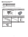
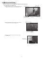
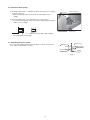
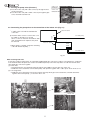
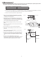
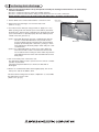
WT06249X01
MITSUBISHI ELECTRIC
Air Conditioning For Building Application
Drain Water Lift-Up Kit
PAC-KE05DM-F
Installation Manual
This installation manual contains only the description of how to install the Drain water Lift-Up Kit PAC-KE05DM-F. For information about how to
wire and how to install air conditioning units, see the installation manual for them.
For your safety, first be sure to read “ 1 Safety Precautions “ described below thoroughly and then install the Drain water Lift-Up Kit PACKE05DM-F correctly.
1 Safety Precautions
● The following two symbols are used to denote dangers that may be caused by incorrect use and their degree:
WARNING
CAUTION
This symbol denotes what could lead to serious injury or death if your misuse the PAC-KE05DM-F.
This symbol denotes what could lead to a personal injury or damage to your property if you misuse the PAC-KE05DM-F.
● After reading this installation manual, keep it in a place where the final user can see it anytime he or she wants to it.
When someone moves, repairs or uses the PAC-KE05DM-F, make sure that this manual is forwarded to the final user.
WARNING
Always have the unit installed by Authorized Mitsubishi
Representative or similar professional.
Improper installation by the user could result in problems such as
water leakage, electric shock or fire.
Install the unit according to this Installation Manual.
If the unit is installed improperly, water leakage, electric shock or
fire may result.
Always use the designated cables and connect them properly.
When connecting the terminals, make sure that external forces
from the cable is not being conveyed to the terminal and then
tighten it securely.
Improper or loose connections could cause excessive heat or fire.
Have all electric work performed by a properly licensed
electrician. Electric work should be performed in strict
adherence to procedures to this Installation Manual. Always
provide a dedicated power supply.
If the capacity of the power supply is inadequate, it could result in
problems such electric shock or fire.
Only use Mitsubishi-approved accessories, such as an air
cleaner, humidifier or electric heater.
Always have such accessories installed by an Authorized Mitsubishi
Representative or similar professional. Improper installation by the
user may result in water leakage, electric shock or fire.
Never modify the unit and always have repairs performed by an
Authorized Mitsubishi Representative.
Improper repair could result in problems such water leakage,
electric shock or fire.
CAUTION
PRECAUTIONS BEFORE INSTALLATION
Never use for special applications such as storing food, plants,
precision equipment or art.
The quality of these items may deteriorate.
Never use the unit in special environments.
Special environments with high concentrations of oil, steam or
sulfuric gases will reduce the performance of the air condition and
cause its parts to deteriorate.
Never install the unit where run-off could result in damage.
If the humidity in the room exceeds 80% or if the drain becomes
clogged, water may drain off of the indoor unit. When the unit is
used for heating, there may be drainage from the outdoor unit. If
required, provide collector drain for the outdoor unit.
Always provide adequate signal noise protection when
installing in facilities such as hospitals and communication
stations.
Equipment at these facilities, such as inverters, in-house generators,
high-frequency medical equipment, two-way communication
equipment, may cause the air conditioner to operate improperly.
Conversely, the signal noise from the air conditioner may affect
the operation of medical equipment and two-way communication
equipment and this could interfere with the medical treatment being
given a patient or cause disturbances or interference in video
broadcasting equipment.
PRECAUTIONS BEFORE REMOVE AND ELECTRIC WORK
Route wiring so that there is no tension.
Tension could cause the wire to break and this could result in
excessive heat or fire.
Dispose of packing materials properly.
PRECAUTIONS BEFORE TEST RUN
Use care when transporting the unit.
•Always use two or more people for lifting a product weight 20 kg.
or more.
•Some products are packaged with plastic wrapping bands.
Never use these for lifting or transporting the product.
•Never touch the fins on the heat exchanger. They are sharp and
could cause cuts.
•Never allow children to play with the plastic bags used for
packaging. Always tear them up when disposing. A child could
suffocate in these bags.
Never touch the switch with wet hands.
Electric shock could occur.
Never operate the air conditioner with the air filter removed.
Particles will enter into the air conditioner and cause damage.
Never operate the air conditioner with the panel or guard
removed.
The hand could come in contact with rotating, hot or high-pressure
components. They could cause electrical shock or entanglement.
Never turn off the power supply immediately after stopping the unit.
Wait five minutes or more before turning off the power supply.
Turning off the power supply before that time could result in water
leakage or damage.
2 Confirming the Supplied Parts
1. Model names and applicable models
Model name
Applicable types
PAC-KE05DM-F
PEFY-P200VMHS-E, PEFY-P250VMHS-E
PEFY-P72NMHSU-E, PEFY-P96NMHSU-E
2. Provided parts
Check that the packet includes the following parts in addition to this installation manual.
PARTS
1DRAIN PUMP ASSY.
2RUBBER PLUG
Drain socket
SHAPE
Float switch
Q'TY
PARTS
1
3BAND (Small)
1
4BAND (Large)
5INSULATION PIPE
SHAPE
Q'TY
PARTS
4
1
6PTT SCREW 4×10
SHAPE
Q'TY
4 + 1 (spare)
1
3 Attach the Drain Pump
The drain pump must be attached before installation of the indoor unit.
3-1 Preparation for the indoor unit
(1) Remove the fixing screws (5 locations) shown Photo 3-1,
and remove the control box cover and the wire cover.
Fixing screw
Control box cover
Fixing screws
Wire cover
Photo 3-1
(2) Remove the fixing screws (3 locations) shown in Photo
3-2, and remove the heat exchanger cover.
Heat exchanger cover
Fixing screws
Photo 3-2
(3) Open the knockout hole shown in Photo 3-3 using a
screwdriver etc.
Knockout hole
Photo 3-3
3-2. Attach the drain pump
(1) Attach the drain pump 1 and drain socket as shown in Photo 3-4 using
four PTT screws 6.
* When attaching the drain socket, make sure that drain hose is
straight.
Drain socket
Drain pump assy 1
(2) Insert the rubber plug 2 into the drain port to close the port.
* To prevent water leakage, make sure that the rubber plug is pushed in
firmly as far as it will go.
Rubber plug 2
Photo 3-4
Do not insert the rubber plub obliquely.
Insert the rubber plug straight.
3-3. Attaching the drain socket
As shown in the drawing below, insert the drain socket into the knockout
hole, and fix it with the PTT screw 6.
Inside unit
Outside unit
Drain socket
6PTT screw
Frame
Fig.3-1
4 Wiring
2-wire cord
4-1. Passing the pump wires (Photo 4-1)
From drain pump
a) Pass the 2-wire cord (with a blue connector) through the hole
shown in the photo.
b) Pass the 2-wire cord (with a white connector) through the pipe
sensor and LEV lead wire hole.
2-wire cord
From float switch
Photo 4-1
4-2. Connecting the pump wires to the control box of the indoor unit (Fig. 4-1)
a) Connect the blue connector of the 2-wire cord
to CNP on the noise filter board inside the
control box.
b) Insert the white connector of the 2-wire cord
into CN4F on the indoor P.C. board.
Since a connector has been inserted into both
CNP and CN4F before shipment, they must
be removed.
Noise filter board
C
N
P
Blue
from drain pump
2-wire cord
Indoor P.C. board
White
CN4F
c) When wiring is complete, fasten the remaining
cords with the band (small) 3.
from float switch
2-wire cord
Fig. 4-1
When fastening lead wires
Power wires and low-voltage wires are separately bundled inside the control box to reduce noise interference. Lead wires
from the Drain Water Lift-Up Kit also need to be bundled separately. Follow the steps below to hold them and the lead
wires inside the control box together.
(1) Power wires
* Feed the lead wires from the drain pump through the wire saddle as shown with "A" in Photo 4-2.
* Bundle the excess lead wires from the drain pump, and clip them together with a cable clip as shown in Photo 4-3.
(2) Low voltage wires
* Bundle the excess lead wires from the float switch, then keep them, pipe sensor lead wires, and LEV lead wires
together with a band (small) 3 as shown in Photo 4-4.
Photo 4-3
Photo 4-2
Photo 4-4
5 Drain piping work
Be sure to wind commercially available insulating material (with a form polyethylene's specific gravity of 0.03
and thickness given below) onto all pipes which pass through rooms.
1 Select the thickness of insulating material by pipe size.
Pipe size
6.4 mm to 25.4 mm
28.6 mm to 38.1 mm
Insulating material's thickness
More than 10 mm
More than 15 mm
2 If the unit is used on the highest story of a building and under conditions of high temperature and humidity, it is necessary
to use pipe size and insulating material's thickness more than those given in the table above.
3 If there are customer's specifications, simply follow them.
1. Ensure that the drain piping is downward (pitch of more than
1/100) to the outdoor (discharge) side. Do not provide any trap
or irregularity on the way. (Fig. 5-1)
Fig. 5-1
25 cm
2. Ensure that any cross-wise drain piping is less than 20 meters
(excluding the difference of elevation). If the drain piping is long,
provide support bracket to prevent it from waving. Never provide
any air vent pipe. Otherwise drain may be ejected.
3. Use a hard vinyl chloride pipe ø32 mm (1-1/4 inch) for drain
piping.
Support bracket
1.5 – 2 m
Downward pitch of
more than 1/100
Fig. 5-2
Take as large as possible. About 10 cm.
Indoor
unit
4. Ensure that collected pipes are 10 cm lower than the unit body’s
drain port. (Fig. 5-2)
Insulation
Indoor
unit
5. Do not provide any odor trap at the drain discharge port.
Indoor
unit
Collective piping
6. Put the end of the drain piping in a position where no odor is
generated.
Fig. 5-3
7. Do not insert the end of the drain piping into any sewer where
sulfuric gases are generated.
Hard vinyl chloride 90°
elbow (field supply)
Less than 300 mm
9. Be sure to use the supplied drain hose (Accessory).
Connect each connection with vinyl chloride adhesive. Otherwise
the Drain Water Lift-Up Kit cannot be serviced later. Also, the
end connection may be eroded by resin and so cracked.
Less than 700 mm
8. The intake of the drain piping can be made 700 mm higher than
the Indoor unit. If there are some obstacles under the ceiling,
use elbows to make it at least height according to the site. (Fig.
5-3)
Hard vinyl
chloride (ø32mm)
(field supply)
Hard vinyl chloride
90° elbow
(field supply)
Drain hose
(Accessory)
Indoor unit
Take the following steps to install the drain hose.
1. Insert the drain hose (supplied with the indoor unit) into the drain port.
(The drain hose must not be bent more than 45° to prevent the hose from breaking or clogging.)
2. Attach the drain pipe (O.D. ø32 PVC TUBE, field supply).
(Attach the pipe with glue for the hard vinyl chloride pipe, and fix it with the band (small) 3.)
3. Perform insulation work on the drain pipe (O.D. ø32 PVC TUBE) and on the socket (including elbow).
4. Follow the steps in the next section to confirm the drain discharge.
5. Wrap the insulation pipe 5 around the connection part between the drain socket and the drain hose, and then install the
band (large) 4.
Edges should be flush with each other!
The seam faces up.
Fig.5-4
Max. 210 ± 5 mm (linear dimensions)
Drain pipe
(O.D. ø32 PVC TUBE)
Drain hose
(field supply)
(supplied with the indoor unit)
Indoor unit
5 Insulation pipe (accessory)
4 Band (large) (accessory)
35
25
25
(Visible part) (Insertion margin)
Insulating material
(field supply)
(Insertion margin)
3 Band (small) (accessory)
Note:
If the rise portion is long, there will be a lot of returned water in an operation stop, generating slime or odor during off-season.
Ensure that the rise portion is at a minimum.
Caution:
Pipe the drain piping to ensure that it discharges drain, and insulate it to prevent dew condensation.
A failure to the piping work may cause water leakage and so wet your property.
6 Confirming drain discharge
▲
Make sure that the Drain Water Lift-Up Kit operates normally for discharge and that there is no water leakage
from the connections.
•Be sure to confirm the above in a period of heating operation.
•Be sure to confirm the above before ceiling work is done in the case of a new construction.
•Before pouring water, be sure to confirm again the rubber plug is pushed in straight all the way.
1. Set the SWE of the control board inside the control box to ON.
Inlet water
Drain hose
2. Remove the heat exchanger cover from the indoor unit.
(Refer to 3-1 (2).)
3. Pour water into the drain pan using a kettle etc. (Approx. 2 to 3 ℓ)
When pouring, make sure that the spout of the kettle is placed into
the drain pan to prevent water overflowing from the drain pan. (If the
spout of the kettle is not placed properly, the water will be poured
outside of the unit.) (Photo 6-1)
(Note 1) If the drain discharge cannot be confirmed even after the
amount of water described above was poured, the unit
may be inclined reversely. Check that the unit is installed
properly (horizontally) with a level. Also, pouring too much
water will immerse the drain pump in water and pose a risk
of malfunctions.
(Note 2) If a submersible pump is used to pour water, adjust the
water amount with a valve so that the water amount will
not exceed 0.4 ℓ/min. Pouring too much water may result in
water leakage from the indoor unit and malfunctions of the
drain pump.
4. Turn on the main power of the indoor unit.
The drain pump will be forced to operate even if no remote controller
operation is performed.
Check the transparent drain hose to make sure that drain is
discharged.
5. When it is confirmed that drain is discharged properly, turn off the
main power, and set the SWE to OFF.
Check that all the wiring work has been completed. If so, reassemble
the drain pipe in reverse order.
(Refer to 3-1 (2)➞(1).)
Photo 6-1