1
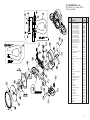
Separation of Pressure
Bar and Gauge
Movement on 5"
Diameter Units up to
20,000 lb/10000 kg
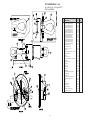
Reassembly of Pressure
Bar and Gauge
Movement on 5"
Diameter Units up to
20,000 lb/10000 kg
If you are installing a new
pressure bar, be sure the
capacity marking on the new
bar matches the marking on
the old bar. The capacity letter
along with other numbers are
located on the narrow side of
the bar between the end of the
radius and the end of the
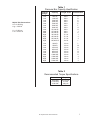
pressure bar. See Table 1 for a
list of letters and capacities.
6
These steps cover disassembly of the 5" diameter units up to 20,000lb/
10000kg capacity to remove the pressure bar.
1.
Remove the three 6-32 x ¼ pan head bezel screws holding the bezel
to the housing.
2.
Lift off the bezel, crystal, and max hand assembly.
3.
Remove two ¼-28 x ¾ socket head cap screws and two ¼ flat washers holding the housing to the pressure bar.
4.
Remove two ¼-28 x ¾ socket head cap screws and two ¼ flat washers holding the gauge movement assembly. Set aside the gauge
movement assembly with the dial inlay and pointer attached.
5.
Remove two ¼-28 x ¾ socket head cap screws and two ¼ flat washers holding the zero adjust bracket. Set aside the zero adjust bracket
assembly.
6.
The pressure bar has four needle bearings. Remove the bearings with
a mechanical press with the plunge ram within ½ degree of the bearing
hole axis. Under no circumstances should the bearings be removed by
impact. Take care that the plunger does not contact the sides of the
bearing hole as you push out the bearing.
These steps cover reassembly of the 5" diameter units up to 20,000lb/
10000kg capacity. See Table 2 for a list of proper torque for the screws.
1.
Reinsert the bearings with a mechanical press with the plunge ram
within ½ degree of the bearing hole axis. Insure that the bearing hole,
bearing outer surface and ram are all free of debris, dirt or particles.
To facilitate bearing installation, an anti-seize compound such as FelPro C5-A may be used, provided any excess lubricant is wiped off after
bearing installation. Carefully insert the bearings one at a time, insuring
that the bearing remains properly aligned to the bearing hole axis.
Reverse sides to install the second bearing. Always assembly the
bearing with the stamped end against the shoulder of the pressing tool.
2.
Attach the zero adjust bracket assembly and the gauge movement
assembly with the four ¼-28 x ¾ socket head cap screws and four ¼
flat washers.
3.
Install the dynamometer housing to the pressure bar with the two ¼-28
x ¾ socket head cap screws and two ¼ flat washers.
4.
Install the bezel assembly to the housing with the three 6-32 x ¼ pan
head bezel screws.
5.
Reinstall shackles and/or hook assemblies.
6.
Calibrate per procedures in the Calibration section of this manual.
AP Dynamometer Service Manual