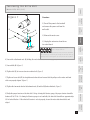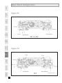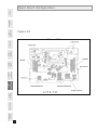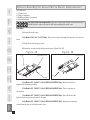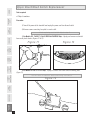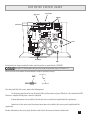
1
H o r i z o n Fitness
Models
T61, T62, T63, T64,
CST 3.5, CST 4.5,
DT650, DT850, WT950,
PST 6, PST 8,
1.2T, 2.2T, 3.2T, 4.2T,
5.2T
2006
Treadmill Service Manual
Table of C ontents
Warranty
3
Safety Instructions
4
Recommended Tools
6
Maintenance
7
Proper Heart Rate Usage
14
Horizon Fitness “5-Step” Diagnostic Process
16
Voltage Checks and LED Diagnosis
18
Wiring Diagrams and Schematics
22
Engineering Mode
31
Troubleshooting
34
Spare Parts Replacement
46
REFER TO THE SUPPLEMENTAL SHEET ON THE LAST PAGE OF THE SERVICE MANUAL
FOR THE MID SEASON PRODUCTION CHANGE ON THE LOWER CONTROL BOARD.
WARRANTY
LIM I T E D H O M E - U S E WARRANTY
SAFETY
INSTRUCTIONS
Horizon Fitness extends the following exclusive, limited warranty, which shall apply to the use of the device in the home,
for residential, non-commercial purposes only. Any other use shall void this warranty.
Horizon Fitness hereby offers the following limited warranties for the following components of the device, for the time
period indicated:
Elevation
7 Years
10 Years
12 Years
15 Years
7 Years
10 Years
12 Years
15 Years
20 Years
22 Years
25 Years
25 Years
25 Years
25 Years
25 Years
12 Years
Frame
Lifetime
Lifetime
Lifetime
Lifetime
Lifetime
Lifetime
Lifetime
Lifetime
Lifetime
Lifetime
Lifetime
Lifetime
Lifetime
Lifetime
Lifetime
Lifetime
RECOMMENDED
TOOLS
Motor
7 Years
10 Years
12 Years
15 Years
7 Years
10 Years
12 Years
15 Years
20 Years
22 Years
25 Years
25 Years
25 Years
25 Years
25 Years
12 Years
MAINTENANCE
Parts
1 Year
1 Year
1 Year
1 Year
1 Year
1 Year
1 Year
1 Year
1 Year
1 Year
2 Years
2 Years
2 Years
2 Years
2 Years
1 Year
PROPER
HEART REATE
USAGE
Labor
1 Year
1 Year
1 Year
1 Year
1 Year
1 Year
1 Year
1 Year
1 Year
1 Year
1 Year
1 Year
1 Year
1 Year
1 Year
1 Year
5-STEP
DIAGNOSTIC
PROCESS
Model
T61
T62
T63
T64
DT650
DT850
CST 3.5
CST 4.5
PST 6
PST 8
1.2T
2.2T
3.2T
4.2T
5.2T
WT950
VOLTAGE CHECKS
AND
LED DIAGNOSIS
Horizon Fitness warranties the frame, electronics, and parts against defects in workmanship and materials for the above
warranty periods, so long as it remains in the possession of the original owner.
Horizon Fitness shall cover the labor cost for the repair of the device for the above warranty periods, so long as the
device remains in the possession of the original owner.
TROUBLESHOOTING
ENGINEERING
MODE
WIRING DIAGRAMS
AND SCHEMATICS
EXCLUSIONS AND LIMITATIONS
This warranty applies only to the original owner and is not transferable. This warranty is expressly limited to the repair
or replacement of a defective frame, electronic component, or defective part. The warranty does not cover normal wear
and tear, improper assembly or maintenance, or installation of parts or accessories not originally intended or compatible
with the treadmill as sold. The warranty does not apply to damage or failure due to accident, abuse, corrosion, discoloration of paint or plastic, or neglect. Horizon Fitness shall not be responsible for incidental or consequential damages.
All returns must be pre-authorized by Horizon Fitness. Horizon Fitness’ obligation under this warranty is limited to
replacing or repairing, at Horizon Fitness’ option, the product at one of its authorized service centers. A Horizon authorized service center must receive all products for which a warranty claim is made. These products must be received with
all freight and other transportation charges prepaid, accompanied by sufficient proof of purchase. Parts and electronic
components reconditioned to As New Condition by Horizon Fitness or its vendors may sometimes be supplied as warranty
replacement parts and constitute fulfillment of warranty terms. This warranty gives you specific legal rights, and your
rights may vary from state to state.
SPARE PARTS
REPLACEMENT
WARRANTY REGISTRATION
Your warranty card must be completed and sent to Horizon Fitness or register on line at www.horizonfitness.com, before a
warranty claim can be processed.
Im p o r t a n t S a f e t y I n s t r u c t i o n s
WARRANTY
Warning statements indicate a particularly dangerous activity.
You should be extremely cautious when doing the following:
SAFETY
INSTRUCTIONS
• Removing power from the treadmill, or removing the power cord from the wall outlet. Always ensure that the treadmill is unplugged from the wall outlet when you inspect or adjust the treadmill, or when you
isolate, remove, or replace a treadmill component.
• Removing the motor cover exposes high voltage components and potentially dangerous machinery.
Exercise extreme caution when you perform maintenance procedures with the motor cover removed.
• During service operations you will be very close to moving machinery and high voltage components.
When you perform maintenance procedures with the hood removed, remove jewelry (especially from ears and
neck), tie up long hair, remove neckties, and do not wear loose clothing.
• When the treadmill is operating, the capacitor will hold a lethal amount of charge. Do not touch the
capacitor as serious injury or death might result.
• When the treadmill is turned off and the power cord is removed from the wall outlet, the capacitor
will hold voltage for 30-60 seconds. Allow the capacitor to discharge for a period of one minute before you
touch or work near the capacitor. Do not attempt to discharge the capacitor by any other means.
• Exercise caution when touching any wire or electrical component during treadmill operation.
• When it is necessary to lift the treadmill, ensure that the treadmill has adequate support. Do not lift
the
treadmill by the front.
RECOMMENDED
TOOLS
MAINTENANCE
PROPER
HEART RATE
USAGE
5-STEP
DIAGNOSIS
PROCESS
Safety guidelines you should know and follow include:
VOLTAGE CHECKS
AND
LED DIAGNOSIS
WIRING DIAGRAMS
AND
SCHEMATICS
ENGINEERING
MODE
TROUBLESHOOTING
SPARE PARTS
REPLACEMENT
• Read the owner’s manual and follow all operation instructions.
• Operate the treadmill on a solid, level surface. Locate the rear of the treadmill at least four feet
from walls or furniture. Keep the area behind the treadmill clear.
• Visually check the treadmill before beginning service or maintenance operations. If it is not completely
assembled or is damaged in any way, exercise extreme caution while operating and checking the treadmill.
• When operating the treadmill, do not wear loose clothing. Do not wear shoes with heels or leather
soles. Check the soles of your shoes and remove any embedded stones. Tie long hair back.
• Use care when getting on or off the treadmill. Use the handrails whenever possible. Do not get on or
off the treadmill when the running belt is moving.
• Before starting the running belt, straddle the belt by placing your feet firmly on the guiderails of the
treadmill. You should also step off the belt and onto the guiderails of the treadmill after turning off the running belt.
• Do not rock the unit. Do not stand or climb on the handrails, electronic console, or motor cover.
• Do not set anything on the handrails, electronic console, or motor cover. Never place liquids on any
part of the treadmill.
• To prevent electrical shock, keep all electrical components, such as the drive motor, power cord, and
circuit breaker away from water and other liquids.
• Do not use accessory attachments that are not recommended by the manufacturer-such attachments might cause injuries.
• Turn off the treadmill when adjusting or working near the rear roller. Do not make any adjustments
to the running belt when someone is standing on the machine.
• Keep all loose items away from the treadmill running surface. A treadmill running belt will not stop
immediately if an object becomes caught in the belt or rollers.
Connect this appliance to a properly grounded, dedicated 20-amp outlet only.
See grounding Instructions.
WARRANTY
WARNING
(SPVOEFE0VUMFU
RECOMMENDED
TOOLS
MAINTENANCE
Improper connection of the equipment-grounding conductor can result in a risk of electric
shock. Check with a qualified electrician if you are in doubt as to whether the product is properly grounded. Do not modify the plug provided with the product, if it will not fit in the outlet;
have a proper outlet installed by a qualified electrician.
Figure 1
PROPER
HEART REATE
USAGE
WARNING
SAFETY
INSTRUCTIONS
GROUNDING INSTRUCTIONS
This product must be grounded. If a treadmill should malfunction or breakdown, grounding provide
a path of least resistance for electrical current to reduce the risk of electrical shock. This product is equipped
with a cord having an equipment-grounding conductor and a grounding plug. The plug must be plugged into
an appropriate outlet that is properly installed and grounded in accordance with local codes and ordinances.
"EBQUFS
5"4'PS
(SPVOEJOH4DSFX
WIRING DIAGRAMS
AND SCHEMATICS
(SPVOEFE0VUMFU#PY
VOLTAGE CHECKS
AND
LED DIAGNOSIS
(SPVOEJOH1JO
5-STEP
DIAGNOSTIC
PROCESS
.FUBM4DSFX
SPARE PARTS
REPLACEMENT
TROUBLESHOOTING
ENGINEERING
MODE
SAFETY TIPS
• Never use the treadmill before securing the safety tether clip to your clothing.
• If you experience chest pains, nausea, dizziness, or shortness of breath, stop exercising
immediately and consult your physician before continuing.
• Do not wear clothes that might catch on any part of the treadmill.
• Keep power cord away from heated surfaces.
• Keep children off of treadmill at all times.
• Do not use treadmill outdoors.
• Unplug treadmill before moving it.
• Do not remove the treadmill motor cover or roller covers.
• Treadmill should be plugged into a dedicated 20 amp circuit for optimal
performance.
Re q u i r e d To o l s a n d E q u i p m e n t
WARRANTY
The following list is a summary of the tools and equipment required by the procedures in this manual.
Tools are not supplied by Horizon Fitness.
SAFETY
INSTRUCTIONS
RECOMMENDED
TOOLS
MAINTENANCE
PROPER
HEART RATE
USAGE
5-STEP
DIAGNOSIS
PROCESS
VOLTAGE CHECKS
AND
LED DIAGNOSIS
WIRING DIAGRAMS
AND
SCHEMATICS
ENGINEERING
MODE
• Phillips screwdrivers
• Anti-static wrist strap (when handling electronic parts)
• Flat-head screwdrivers
• Digital multi-meter
• Drive belt tension gauge
• Allen wrench set (Metric)
• Open-end wrenches of assorted sizes (Metric)
• Clamp-on amp meter
• 1⁄2” drive ratchet and sockets of assorted sizes
• Blue Thread Lock
• Cable ties
• Motor commutator stone
• Needle nose pliers
• Damp cloth
• Rubber mallet
• Drop cloth
• Ruler
• Snap ring pliers
• Wire cutters
TROUBLESHOOTING
Note:
The motor commutator stone can be ordered from Horizon Fitness.
SPARE PARTS
REPLACEMENT
WARRANTY
Preventativ e M a i n t e n a n c e P r o c e d u r e s
Cleanliness of your Horizon Fitness treadmill and its operating environment will keep maintenance
problems and service calls to a minimum. For this reason, Horizon Fitness recommends that the following
SAFETY
INSTRUCTIONS
preventive maintenance schedule be followed.
After Each Use
WARNING
RECOMMENDED
TOOLS
• Turn off the treadmill with the on/off switch, and unplug the power cord from the wall outlet.
To remove power from the treadmill, the power cord must be disconected from the wall outlet.
MAINTENANCE
• Wipe down the running belt, deck, motor cover, and console casing with a damp cloth. Never use
• Inspect the power cord. If the power cord is damaged, contact Horizon Fitness.
• Make sure the power cord is not underneath the treadmill or in any other area where it can become
PROPER
HEART REATE
USAGE
solvents, as they can cause damage to the treadmill.
pinched or cut.
• Check the tension and alignment of the running belt. Make sure that the treadmill belt will not
5-STEP
DIAGNOSTIC
PROCESS
damage any other components on the treadmill by being misaligned.
VOLTAGE CHECKS
AND
LED DIAGNOSIS
Every Week
• Turn off the treadmill with the on/off switch.
• Unplug the power cord at the wall outlet.
• Fold the treadmill into the upright position; making sure that the foot lock latch is secure.
• Move the treadmill to a remote location.
• Wipe or vacuum any dust particles or other objects that may have accumulated underneath the
WIRING DIAGRAMS
AND SCHEMATICS
Clean underneath the treadmill, following these steps:
ENGINEERING
MODE
treadmill.
• Return the treadmill to its previous position.
TROUBLESHOOTING
Every Month
• Inspect all assembly bolts of the machine for proper tightness.
• Add lubrication to deck and running belt. Use lubrication provided by Horizon Fitness only!
• Lubricate the air shocks with a Teflon based spray.
SPARE PARTS
REPLACEMENT
Each 3-6 months
Te n s i o n i n g t h e R u n n i n g B e l t
WARRANTY
If you can feel a slipping sensation when running on the treadmill, the running belt must be tight-
SAFETY
INSTRUCTIONS
ened. In most cases, the belt has stretched from use, causing the belt to slip. This is a normal and common
adjustment. Make sure that the unit is turned off and not running. To eliminate this slipping, tension both
the rear roller bolts with the appropriate sized Allen wrench, turning both the left and right bolt 1/4 TURN as
RECOMMENDED
TOOLS
shown below. Try the treadmill again to check for slipping. Repeat if necessary, but NEVER TURN the roller
bolts more than 1/4 turn at a time. MAINTENANCE
PROPER
HEART RATE
USAGE
Figure 2
5-STEP
DIAGNOSIS
PROCESS
VOLTAGE CHECKS
AND
LED DIAGNOSIS
WIRING DIAGRAMS
AND
SCHEMATICS
ENGINEERING
MODE
5FOTJPOJOH5IF3VOOJOHCFMU
TROUBLESHOOTING
SPARE PARTS
REPLACEMENT
WARRANTY
Aligining th e R u n n i n g B e l t
1) If the running belt moves rapidly to one side when performing the next step, press the Stop button
SAFETY
INSTRUCTIONS
immediately.
• Turn on the treadmill. With the treadmill speed between 6-8 mph, stand behind the treadmill and watch the
RECOMMENDED
TOOLS
movement of the running belt. As you watch the running belt, make sure that the belt runs without moving
MAINTENANCE
from one side to the other and that the belt is centered between the side rails.
2) If the running belt is not tracking properly, follow the procedures below:
• If the running belt tracks to the left, turn the left roller bolt clockwise 1⁄4 of a turn, keeping the belt tension
PROPER
HEART REATE
USAGE
in mind. Over-tightening the running belt may cause damage to the running belt and roller bearings.
• If the running belt tracks to the right, turn the right roller bolt clockwise 1⁄4 of a turn, keeping the belt ten-
VOLTAGE CHECKS
AND
LED DIAGNOSIS
Figure 3
5-STEP
DIAGNOSTIC
PROCESS
sion in mind. Over-tightening the running belt may cause damage to the running belt and roller bearings.
#FMUJTUPPGBSUPUIFSJHIUTJEF
SPARE PARTS
REPLACEMENT
#FMUJTUPPGBSUPUIFMFGUTJEF
TROUBLESHOOTING
ENGINEERING
MODE
WIRING DIAGRAMS
AND SCHEMATICS
Figure 4
Te n s i o n i n g t h e D r i v e B e l t
(Models: T61, T62, T63, T64 , C S T 3 . 5 , C S T 4 . 5 , D T 6 5 0 , 1 . 2 T, 2 . 2 T, 3 . 2 T, 4 . 2 T, D T 8 5 0 , W T 9 5 0 )
WARRANTY
SAFETY
INSTRUCTIONS
Figure 5
"
$
F i gure 6
#
RECOMMENDED
TOOLS
"
$
MAINTENANCE
#
Procedure:
PROPER
HEART RATE
USAGE
1) Turn off the power to the treadmill and remove the power cord from the wall outlet.
5-STEP
DIAGNOSIS
PROCESS
2) Remove the motor cover.
3) Unplug the motor wires from the motor control board.
VOLTAGE CHECKS
AND
LED DIAGNOSIS
Before contin u i n g , i t i s a g o o d i d e a t o w e i g h d o w n t h e t r e a d m i l l d e c k t o p r event the tread m i l l f r o m s p r i n g i n g u p . R e m o v i n g t h e w e i g h t o f t h e m o t o r w i l l
significantly r e d u c e t h e w e i g h t i n t h e f r o n t e n d o f t h e t r e a d m i l l .
WIRING DIAGRAMS
AND
SCHEMATICS
ENGINEERING
MODE
4) Loosen the attachment nuts (A) holding the motor bracket to the frame. (Figures 5 & 6)
5) Tighten bolt (B) to increase tension on drive belt. (Figures 5 & 6)
6) Tighten or loosen bolt (C) to straighten motor bracket and ensure that the pulleys on the motor and front
roller are properly aligned. (Figures 5 & 6)
TROUBLESHOOTING
7) Tighten the two motor bracket attachment nuts (A) when finished. (Figures 5 & 6)
8) Verify the proper tension on the drive belt. Using a timing belt tension gauge, the proper tension should be
SPARE PARTS
REPLACEMENT
between 65 to 75 lbs. If a timing belt tension gauge is not available, the drive belt should have approximately 3/8 of
inch deflection. If the drive belt tension is not set properly, loosen the motor attachment bolts and adjust.
10
Tensioning t h e D r i v e B e l t
%
Procedure:
1) Turn off the power to the treadmill and remove the power cord from the wall outlet.
#
SAFETY
INSTRUCTIONS
RECOMMENDED
TOOLS
F igure 7
WARRANTY
(Models: PST6, PST 8, 5.2T)
"
2) Remove the motor cover.
3) Unplug the motor wires from the mo
tor control board.
Before continuing, it is a good idea to weigh down the
treadmill deck to prevent the treadmill
PROPER
HEART REATE
USAGE
MAINTENANCE
$
from springing up. Removing the weight of the motor will sig5-STEP
DIAGNOSTIC
PROCESS
nificantly reduce the weight in the front end of the treadmill.
4) Loosen the attachment nuts (A) holding the motor bracket to the frame. (Figure 7)
VOLTAGE CHECKS
AND
LED DIAGNOSIS
5) Loosen Bolt (B). (Figure 7)
WIRING DIAGRAMS
AND SCHEMATICS
6) Tighten bolt (C) to increase tension on drive belt. (Figure 7)
7) Tighten or loosen bolt (D) to straighten motor bracket and ensure that the pulleys on the motor and front
roller are properly aligned. (Figure 7)
ENGINEERING
MODE
8) Tighten the two motor bracket attachment nuts (A) and bolt (B) when finished. (Figure 7)
TROUBLESHOOTING
9) Verify the proper tension on the drive belt. Using a timing belt tension gauge, the proper tension should be
between 65 to 75 lbs. If a timing belt tension gauge is not available, the drive belt should have approximately
3/8 of inch deflection. If the drive belt tension is not set properly, loosen the motor attachment bolts and
SPARE PARTS
REPLACEMENT
adjust.
11
St o n i n g t h e M o t or C o m m u t a t o r
WARRANTY
1) Unplug the power cord from the wall outlet.
SAFETY
INSTRUCTIONS
D o n o t p l u g i n t h e p o w e r c o r d a n d d o n o t t u r n o n t h e t r e a d m i l l w h e n the motor
b r u s h e s a r e r e m o v e d f r o m t h e d r i v e m o t o r.
2) Remove the brush covers on the drive motor.
RECOMMENDED
TOOLS
3) Gently insert commutator stone into motor so that it makes contact with commutator.
Figure 49
MAINTENANCE
$PNNVUBUPS
PROPER
HEART RATE
USAGE
5-STEP
DIAGNOSIS
PROCESS
$PNNVUBUPS4UPOF
VOLTAGE CHECKS
AND
LED DIAGNOSIS
4) Spin the motor flywheel by hand until any abnormal marks are removed and the commutator has a
shiny copper finish.
WIRING DIAGRAMS
AND
SCHEMATICS
ENGINEERING
MODE
TROUBLESHOOTING
SPARE PARTS
REPLACEMENT
12
5) Blow any dust and particles with compressed air from the motor commutator when finished.
6) Run the treadmill for 15 minutes at 3-5 mph to seat the brushes properly.
7) Inspect the motor commutator again for any unusual wear.
8) Repeat stoning process if necessary.
WARRANTY
Treadmill D e c k P r o c e d u r e s
There are three different situations where you would be required to add lubrication to a Horizon Fitness treadmill.
SAFETY
INSTRUCTIONS
1. MAINTENANCE
Silicone needs to be applied to a Horizon Fitness treadmill regularly. Horizon Fitness recommends that lubrication be
applied every three to six months depending on the number of users and the frequency of use.
RECOMMENDED
TOOLS
3VOOJOH#FMU
MAINTENANCE
3VOOJOH%FDL
Silicone Oil Application
PROPER
HEART REATE
USAGE
Figure 8
5-STEP
DIAGNOSTIC
PROCESS
2. BELT REPLACEMENT
When lubrication is added to a treadmill deck at the factory it is infused into the filament backing of the running belt,
providing a low friction, long lasting coat. When replacing the original belt on a treadmill, this new belt will not be
properly coated. Always add lubrication when replacing the belt.
VOLTAGE CHECKS
AND
LED DIAGNOSIS
3. BREAKER TRIPS
With time, the lubrication between the running deck and running belt of the treadmill will wear down. The lack of lubrication between the deck and belt will cause a high amount of friction when running on the treadmill. This, in turn, will
cause the treadmill breaker to trip. If this happens, lubrication should be added.
WIRING DIAGRAMS
AND SCHEMATICS
a. With the 6mm Allen wrench loosen the bolts that hold the rear roller in place. It is not necessary to take off
the roller, just loosen it enough so that you can fit your hands underneath the belt comfortably.
It is a good idea to note the position of the rear roller before removing. For best
results, place two removable marks on the left and right side of the deck and the running belt. When reinstalling, match up the marks for proper tension.
ENGINEERING
MODE
b. Take a small amount of silicon oil (20 cc squeeze bottle provided by Horizon Fitness) and apply it to the
entire top surface of the running deck.
c. Tighten rear roller to proper position.
SPARE PARTS
REPLACEMENT
Please contact the Horizon Fitness service department to obtain the proper lubrication for
reapplication.
TROUBLESHOOTING
d. Wipe off any excessive silicon oil that may have seeped out from underneath the
running belt with a damp cloth.
13
Pr o p e r H e a r t R a te U s a g e
WARRANTY
SAFETY
INSTRUCTIONS
HAND GRIPS
Place the palm of you hands directly on the grip pulse handlebars. Both hands must grip the bars for your heart rate to
register. It takes 5 consecutive heartbeats (15-20 seconds) for your heart rate to register accuratly. When gripping the pulse handlebars, do not grip tightly. Holding the grips tightly may elevate your blood pressure. Keep a loose, cupping hold. You may experience
an erratic readout if consistently holding the grip pulse handlebars. Make sure to clean the pulse sensors to ensure proper contact
can be maintained.
RECOMMENDED
TOOLS
WIRELESS CHEST TRANSMITTER
(T64 & 4.2 Chest strap sold separately, PST 8, 5.2T)
Prior to wearing the wireless chest transmitter, moisten the two rubber electrodes with water. Center the chest strap just
below the breast or pectoral muscles, directly over your sternum, with the logo facing out.
MAINTENANCE
The chest strap must be tight and properly placed to receive an accurate and consistent readout. If the chest strap is too loose, or positioned improperly, you may receive
an erratic or inconsistent heart rate readout.
WARNING
PROPER
HEART RATE
USAGE
T h e h e a r t r a t e function is not a medical device. Various factors may affect the accur a c y o f y o u r h eart rate reading. The heart rate reading is intended only as an exercise
aid.
Figure 9
Figure 10
#"$,4*%&0'$)&4553"/4.*55&3
5-STEP
DIAGNOSIS
PROCESS
VOLTAGE CHECKS
AND
LED DIAGNOSIS
"11-:.0*4563&)&3&
TROUBLESHOOTING-HEART RATE
WIRING DIAGRAMS
AND
SCHEMATICS
Check your exercise environment for sources of interference such as fluorescent lights, computers, underground
fencing, home security systems or appliances containing large motors. These items may cause erratic heart rate readouts.
You may experience an erratic readout under the following conditions:
ENGINEERING
MODE
• Gripping the heart rate handlebars too tight. Try to maintain moderate pressure while holding onto the heart rate
handlebars.
• Constant movement and vibration due to constantly holding the heart rate handlebars while exercising. If you are
receiving erratic heart rate readouts, try to only hold the grips long enough to monitor your heart rate.
TROUBLESHOOTING
• When you are breathing heavily during a workout.
• When your hands are constricted by wearing a ring.
• When your hands are dry or cold. Try to moisten your palms by rubbing them together to warm them.
• Anyone with heavy arrhythmia.
SPARE PARTS
REPLACEMENT
• Anyone with arteriosclerosis or peripheral circulation disorder.
• Anyone whose skin on the measuring palm is especially thick.
14
WARRANTY
Lubricating t h e A i r S h o c k
SAFETY
INSTRUCTIONS
Procedure:
1) Fold the treadmill to the upright position; making sure the treadmill is locked securely.
2) Add lubricating oil on the shaft of the air shock.
MAINTENANCE
RECOMMENDED
TOOLS
3) Lift the frame up and down, repeating this several times to allow the lubricating oil blend into air
PROPER
HEART REATE
USAGE
Figure 11
TROUBLESHOOTING
ENGINEERING
MODE
WIRING DIAGRAMS
AND SCHEMATICS
VOLTAGE CHECKS
AND
LED DIAGNOSIS
5-STEP
DIAGNOSTIC
PROCESS
"JS4IPDL
SPARE PARTS
REPLACEMENT
shock
15
Fi v e - S t e p D i a g n o s i s P r o c e s s
WARRANTY
SAFETY
INSTRUCTIONS
The following steps are provided as routine checkpoints when diagnosing problems on a H orizon Fitness treadmill. If followed correctly, these checkpoints
should help diagnos the majority of problems that may be encountered.
1. Proper supplying power to treadmill.
RECOMMENDED
TOOLS
• Make sure the treadmill is not on an extension cord or surge protector. Extension cords and surge protectors
create energy loss, which prevents proper voltage from being supplied to the treadmill.
• Make sure the treadmill is on a dedicated circuit. Horizon Fitness recommends a 20 amp dedicated circuit,
but a 15 amp dedicated circuit may be sufficient.
MAINTENANCE
• Make sure that proper voltage is being supplied from the wall outlet.
PROPER
HEART RATE
USAGE
H a z a r d o u s v o l tages will be tested in the following procedure.
E x e r c i s e e x t r e me caution when performing these procedures. Do not connect or
WARNING
d i s c o n n e c t a n y wiring, connectors, or other components with the power applied to the
treadmill.
• Disconnect the treadmill power cord from the wall outlet. Using an AC voltmeter, verify that the proper AC
voltage is present at the wall outlet. Nominal 120 volts AC may vary between approximately 105 volts AC and 135 volts
AC. If the AC voltage is missing or incorrect, check the AC service or consult an electrician.
5-STEP
DIAGNOSIS
PROCESS
Figure 12
VOLTAGE CHECKS
AND
LED DIAGNOSIS
7"$
WIRING DIAGRAMS
AND
SCHEMATICS
ENGINEERING
MODE
TROUBLESHOOTING
2. Proper Wiring
• Verify that all wires are secure and attached in the correct position. (Reference Wiring Diagrams and Sce-
matics section.)
SPARE PARTS
REPLACEMENT
• Verify that there aren’t any pinches or cuts in any of the wires, especially the console cable connecting from
the motor control board to the upper board. Replace any wires that are pinched or cut.
16
WARRANTY
Fiv e-Step D i a g n o s i s P r o c e s s
3. Proper Motor Function
RECOMMENDED
TOOLS
Fig u r e 1 3
SAFETY
INSTRUCTIONS
• Verify that the treadmill is properly lubricated (Reference Maintenance Section) and drive motor is
operating at the proper amperage rating. To verify the current draw, place a clamp meter around the red motor
wire. If a clamp meter is not available, an additional wire harness can be produced to measure amperage
with a standard voltmeter.
Figure 14
#MBDL.PUPS
$POOFDUJPO
61
3
3
-&% %
2
4+&%&&
-&% 2
-&% 2
;+
51
%
3
$
$ 64
MAINTENANCE
/5$
$0*-7%$
$
+29'4"
"7 "$
+1
$
6
6
%
3
$
3
2
%
-
51
%
3
$
3
4(/%
+0)/40/'*5/&44
3
-&% 3
3
$
3
$
3
$
3
$
3
2
%8
% ';
$)*/ "
$2$
8+5
3
$)* / "
+29'4"
$2$
$0*- 7%$
$ 64
"7 "$
3FE.PUPS
$POOFDUJPO
3
%
3
3
$
%
2
%-4
3
%
%
51
%-4 #-
3
/5$
%
3
$
#MBDL.PUPS
8JSF
PROPER
HEART REATE
USAGE
3FE.PUPS8JSF
• Remove the brush covers on the drive motor and inspect the brushes and the motor commutator
5-STEP
DIAGNOSTIC
PROCESS
for any uneven wear. If the surface of the motor brush is pitted, rough, has burn marks, or the commutator
has a black residue on it, replace the motor brush and stone the motor commutator. (Reference Motor Brush
VOLTAGE CHECKS
AND
LED DIAGNOSIS
Replacement and Stoning the Commutator in Spare Parts Replacement Section.)
4. Proper Speed Calibration
• To ensure proper belt speed and proper calibration use engineering mode to verify that machine is
WIRING DIAGRAMS
AND SCHEMATICS
running in MPH not KM (all models) and that the correct roller diameter is set (1.2T - 5.2T only). (Reference
Engineering Mode Section.)
• Auto-calibrate the machine from engineering mode if the belt speed is erratic or the belt speed does
ENGINEERING
MODE
not correspond to what is displayed on the console. (Reference Engineering Mode Section.)
5. Voltage Checkpoints/Diagnostic LED’s
• Verify that the motor control board is functioning properly by referencing the Diagnostic LED’s
• Verify that proper voltage is being transferred through the console cable.
If the techniques described in the five-step diagnostic process did not resolve the problem, reference the
symptoms in the table of contents and review other possible causes in the troubleshooting section.
SPARE PARTS
REPLACEMENT
TROUBLESHOOTING
located on the lower control board. (Reference Voltage Checks & LED Diagnosis Section.)
17
Co n s o l e C a b l e V o l t a g e C h a r t ( D C V o l t s )
WARRANTY
F i g u r e 15
SAFETY
INSTRUCTIONS
#*ODMJOF7$$
#*ODMJOF1PU
#*ODMJOF(/%
#%JHJUBM(/%
#%JHJUBM(/%
#31.
#1PXFS7PMUBHFUP6$#
RECOMMENDED
TOOLS
#1PXFS7PMUBHFUP6$#
#4QFFE$PNNBOE18.
#%SJWF.PUPS3FMBZ
#*ODMJOF%PXO
#*ODMJOF6Q
$033&$570-5"(&'038*3&)"3/&44
MAINTENANCE
##MBDLWEDDPOTUBOU ##MVFWEDDPOTUBOU3BOHFUPWEED
##SPXOWEDBUJODMJOFWEDBUNBYJODMJOF #1VSQMFWEDDPOTUBOU3BOHFUPWED
7PMUBHFDIBOHFTXJUIFBDIDIBOHFJOJODMJOF #(SFZWEDCFGPSFTUBSUFEWEDBUNQIWEDBUNQI
##SPXOOBHSPVOE 7PMUBHFDIBOHFTBTTQFFEDIBOHFT
#0SBOHFOBHSPVOE #8IJUFWEDCFGPSFTUBSUFEWEDBGUFSTUBSUFE
#:FMMPXOBHSPVOE #1JOLWEDCFGPSFTUBSUFEWEDXIJMFJODMJOJOH
#(SFFO8IFOTQFFETFOTPSBMJHOFEUPNBHOFUTIPSU
WEDXIJMFEFDMJOJOH7PMUBHFDPOTUBOUXIJMFJODMJOJOHEFDMJOJOH
WED8IFOTFOTPSOPUBMJHOFEPQFOWED #-U#MVFWEDCFGPSFTUBSUFEWEDXIJMFJODMJOJHWED
XIJMFEFDMJOJOH7PMUBHFDPOTUBOUXIJMFJODMJOJOHEFDMJOJOH
PROPER
HEART RATE
USAGE
Console Cable Voltage Check
5-STEP
DIAGNOSIS
PROCESS
Figure 16
VOLTAGE CHECKS
AND
LED DIAGNOSIS
V DC
WIRING DIAGRAMS
AND
SCHEMATICS
GND
GND
M
VD
P
Mo
Dow
UP
ENGINEERING
MODE
TROUBLESHOOTING
To check the voltage of a specific function (i.e. elevation, motor control, etc), place the negative lead of your
multi-meter on pin B3, B4 or B5, and place the positive lead on the desired pin. Follow the voltage chart
above for the correct voltages.
SPARE PARTS
REPLACEMENT
Wire colors are subject to change.
18
"$8JSFT
ENGINEERING
MODE
7"$
WIRING DIAGRAMS
AND SCHEMATICS
VOLTAGE CHECKS
AND
LED DIAGNOSIS
Figure 18
TROUBLESHOOTING
Spin motor flywheel to produce voltage
5-STEP
DIAGNOSTIC
PROCESS
PROPER
HEART REATE
USAGE
MAINTENANCE
7%$
RECOMMENDED
TOOLS
SAFETY
INSTRUCTIONS
Figure 17
SPARE PARTS
REPLACEMENT
Motor Voltage Check
WARRANTY
Motor/AC W i r e V o l t a g e C h e c k
AC Wire Voltage Check
19
Lo w e r B o a r d L E D D i a g n o s i s
WARRANTY
Figure 19 a
R5
D5
UP
R7
R9
Q4
SJED08043EE
LED4
LED5
Q2
LED 4
LED3
Q1
ZJ
R6
LED 2
CQC
C
R14
TP1
R29
C9
US
NTC
COIL 12VDC
JQX-15FS-A
30A 120/240VAC
D18
D10
C8
U1
U3
D17
L3
R24
D20
07
R32
R33
C33
08
D9
MAINTENANCE
C1
Q9
SGND
TP4
D6
JP5
C30
R35
D3 FZ
CHINA
CHINA
R28
C34
12
JOHNSONFITNESS
R8
LED2
US
JQX-15FS-A
COIL 12VDC
CQC
WJ28025T
08
04
LED 3
30A 120/240VAC
C
RECOMMENDED
TOOLS
DW
R26
R27
C14
R10
C15
R11
C16
R12
C17
R13
Q3
SAFETY
INSTRUCTIONS
LED 5
Q10
DLS3
R17
NTC
DLS2
D1
D21
D19
TP2
BL
R19
LED 1
2%$
LED 1
R18
C20
PROPER
HEART RATE
USAGE
5-STEP
DIAGNOSIS
PROCESS
VOLTAGE CHECKS
AND
LED DIAGNOSIS
LED 1: Transfer indicators - When the power switch is turned on, LED 1 lights up, meaning that power is supplied to the lower board. This LED should remain on while operating the drive motor and elevation motor. If
the LED’s are not lit, check the AC service from the wall outlet.
WIRING DIAGRAMS
AND
SCHEMATICS
LED 2 & 3: Motor indicator - The LED 3 will come on if the motor starts to run. The motor control board will
begin detecting the status of the motor and if everything is OK then LED 2 will turn on in 1 or 2 seconds.
LED 4 & 5: Incline Motor Indicator - When the upper board is commanding the incline motor to move UP or
DOWN, the LED’s go on. LED 4 is for the UP function, and LED 5 is for the DOWN function.
ENGINEERING
MODE
TROUBLESHOOTING
SPARE PARTS
REPLACEMENT
20
WARRANTY
Lower Boar d L E D D i a g n o s i s
SAFETY
INSTRUCTIONS
Figure 19 b
LED 4
LED 5
LED 2
Q15
R34
MODEL-SDH-T046
CQC
CHINA
DF26
C
USE
JP2
C28 R26
CQC
SGND
Q6 R1
R12
S/N J505-07-26-0068
P3
Q7 R32
R2
VER:H101
C39 C38
Q14R35
R33
UP
DW
R11
JDYFL01 REV f 05.05.12
C12 C14
JOHNSONFITNESS
US
CHINA
DF26
C
US
COIL 12VDC
D18
GND_S
JQX-15FS-A
AC2
30A 120/240VAC
R13
C26
C30
D17
R14
TZR1
C36
C31
Q8
0527
C35
Q5
U1
U2
D19 R31
C33
C37U3C 1
R7
D13
D4
R4
AC1
C6
QC
0
OK 4
D2
D3
R8 Q12 Q4
7 D10 D7 R9 D9
BL
NTC1
PROPER
HEART REATE
USAGE
36 R16
JQX-15FS-A
C24 R1
NTC1
MAINTENANCE
R28
R27
30A 120/240VAC
COIL 12VDC
C40
06
D14 D8 D16
C25
MT0302038
WJ28025T
05
RECOMMENDED
TOOLS
LED 3
R23
GND_P
RED
Q10 Q2
R22
R5
Q3
R24
C20
R19
R6
R21
R20
D6
JP1
C3
5-STEP
DIAGNOSTIC
PROCESS
LED 1
VOLTAGE CHECKS
AND
LED DIAGNOSIS
LED 1: DC Voltage Indicator - When the power switch is turned on, LED 1 dimly lights up. If the belt begins to
run LED1 will remain. Power is stored in the board, do not touch.
WIRING DIAGRAMS
AND SCHEMATICS
LED 2 & 3: Motor indicator - The LED 3 will come on if the motor starts to run. The motor control board will
begin detecting the status of the motor and if everything is OK then LED 2 will turn on in 1 or 2 seconds.
SPARE PARTS
REPLACEMENT
TROUBLESHOOTING
ENGINEERING
MODE
LED 4 & 5: Incline Motor Indicator - When the upper board is commanding the incline motor to move UP or
DOWN, the LED’s go on. LED 4 is for the UP function, and LED 5 is for the DOWN function.
21
Di g i t a l D r i v e W i r i n g D i a g r a m
SAFETY
INSTRUCTIONS
Optic Speed Sensor
BLACK
WHITE
RED
BLUE
BLACK
GREEN
+GND
PULSE
+5V
GND
GND
MAINTENANCE
Speed Sensor
Drive Motor
0-90 VDC
BLACK
RED
Digital Ground
5-STEP
DIAGNOSIS
PROCESS
MCB
Digital Ground
PROPER
HEART RATE
USAGE
EL - Vcc (+2.5v)
EL - Pot
Gnd
RECOMMENDED
TOOLS
VOLTAGE CHECKS
AND
LED DIAGNOSIS
BLACK
RED
WHITE
WHITE
BLACK
WIRING DIAGRAMS
AND
SCHEMATICS
+2.5vdc
EL. Pol
EL. GND
GREEN
BREAKER
ENGINEERING
MODE
Incline Motor
GREEN
WHITE
BLACK
Power Cord
110-120 VAC
TROUBLESHOOTING
SPARE PARTS
REPLACEMENT
22
RPM
Power Voltage (+15V)
Power Voltage (+15V)
Speed Command pwr
RELAY
DOWN Incline
UP Incline
WARRANTY
Figure 20
WARRANTY
Power Sour c e W i r i n g D i a g r a m
&
"
'
RECOMMENDED
TOOLS
%
SAFETY
INSTRUCTIONS
Figure 21
#
'
MAINTENANCE
"
$
$
0/0''
48*5$)
#3&",&3
PROPER
HEART REATE
USAGE
40$,&5
VOLTAGE CHECKS
AND
LED DIAGNOSIS
5-STEP
DIAGNOSTIC
PROCESS
A – Socket wire to breaker or on/off switch. Wire l e n g t h w i l l d e t e r m i n e c o n n e c t i o n p o i n t .
B – Ground
Wire l e n g t h w i l l d e t e r m i n e c o n n e c t i o n p o i n t .
C – Socket wire to breaker or on/off switch. D – On/Off switch to motor control board.
WIRING DIAGRAMS
WIRING DIAGRAMS
AND
AND SCHEMATICS
SCHEMATICS
E – On/Off switch to motor control board.
SPARE PARTS
REPLACEMENT
TROUBLESHOOTING
ENGINEERING
MODE
F – On/Off switch to breaker.
23
Up p e r B o a r d C o n f i g u r a t i o n s
WARRANTY
SAFETY
INSTRUCTIONS
Fig u r e 2 2
RECOMMENDED
TOOLS
MAINTENANCE
PROPER
HEART RATE
USAGE
T61 & T62
5-STEP
DIAGNOSIS
PROCESS
VOLTAGE CHECKS
AND
LED DIAGNOSIS
Fig u r e 2 3
WIRING DIAGRAMS
AND
SCHEMATICS
ENGINEERING
MODE
TROUBLESHOOTING
SPARE PARTS
REPLACEMENT
T63
24
DT650
SPARE PARTS
REPLACEMENT
TROUBLESHOOTING
ENGINEERING
MODE
WIRING DIAGRAMS
WIRING DIAGRAMS
AND
AND SCHEMATICS
SCHEMATICS
Fig u r e 2 5
VOLTAGE CHECKS
AND
LED DIAGNOSIS
5-STEP
DIAGNOSTIC
PROCESS
PROPER
HEART REATE
USAGE
MAINTENANCE
RECOMMENDED
TOOLS
Fig u r e 2 4
SAFETY
INSTRUCTIONS
WARRANTY
Upper Boar d C o n f i g u r a t i o n s
T64
25
Up p e r B o a r d C o n f i g u r a t i o n s
WARRANTY
SAFETY
INSTRUCTIONS
Fig u r e 2 6
RECOMMENDED
TOOLS
MAINTENANCE
PROPER
HEART RATE
USAGE
DT850
5-STEP
DIAGNOSIS
PROCESS
VOLTAGE CHECKS
AND
LED DIAGNOSIS
Fig u r e 2 7
WIRING DIAGRAMS
AND
SCHEMATICS
ENGINEERING
MODE
TROUBLESHOOTING
SPARE PARTS
REPLACEMENT
CST 3.5
26
PST6
SPARE PARTS
REPLACEMENT
TROUBLESHOOTING
ENGINEERING
MODE
WIRING DIAGRAMS
WIRING DIAGRAMS
AND
AND SCHEMATICS
SCHEMATICS
Fig u r e 2 9
VOLTAGE CHECKS
AND
LED DIAGNOSIS
5-STEP
DIAGNOSTIC
PROCESS
PROPER
HEART REATE
USAGE
MAINTENANCE
RECOMMENDED
TOOLS
Fig u r e 2 8
SAFETY
INSTRUCTIONS
WARRANTY
Upper Boar d C o n f i g u r a t i o n s
CST 4.5
27
Up p e r B o a r d C o n f i g u r a t i o n s
WARRANTY
SAFETY
INSTRUCTIONS
Fi g u r e 3 0
RECOMMENDED
TOOLS
MAINTENANCE
PROPER
HEART RATE
USAGE
PST8
5-STEP
DIAGNOSIS
PROCESS
VOLTAGE CHECKS
AND
LED DIAGNOSIS
Fi g u r e 3 1
WIRING DIAGRAMS
AND
SCHEMATICS
ENGINEERING
MODE
TROUBLESHOOTING
SPARE PARTS
REPLACEMENT
1.2T
28
3.2T
SPARE PARTS
REPLACEMENT
TROUBLESHOOTING
ENGINEERING
MODE
WIRING DIAGRAMS
WIRING DIAGRAMS
AND
AND SCHEMATICS
SCHEMATICS
Fi g u r e 3 3
VOLTAGE CHECKS
AND
LED DIAGNOSIS
5-STEP
DIAGNOSTIC
PROCESS
PROPER
HEART REATE
USAGE
MAINTENANCE
RECOMMENDED
TOOLS
Fi g u r e 3 2
SAFETY
INSTRUCTIONS
WARRANTY
Upper Boar d C o n f i g u r a t i o n s
2.2T
29
Up p e r B o a r d C o n f i g u r a t i o n s
WARRANTY
SAFETY
INSTRUCTIONS
RECOMMENDED
TOOLS
Fig u r e 3 4
MAINTENANCE
PROPER
HEART RATE
USAGE
5-STEP
DIAGNOSIS
PROCESS
VOLTAGE CHECKS
AND
LED DIAGNOSIS
WIRING DIAGRAMS
AND
SCHEMATICS
ENGINEERING
MODE
4.2T & 5.2T
TROUBLESHOOTING
SPARE PARTS
REPLACEMENT
30
Engineering M o d e
WARRANTY
(Models: T61, T62, T63, T64, CST 3.5, CST 4.5, DT650, DT850, WT950, PST 6, PST 8)
Entering Engineering Mode
SAFETY
INSTRUCTIONS
Press and hold “Stop” to exit all engineering modes.
Power on the treadmill and have the safety key in position on the console. Press and hold the elevation “+” and speed “-” for about 5 seconds to enter the Engineering Mode Menu. The console should beep three times and Eng0 should be displayed once in
the Engineering Mode Menu.
RECOMMENDED
TOOLS
Eng0 – Display and Button Check
1. While in the Engineering Mode Menu, press Speed “+” or “-” until Eng0 appears in the display.
2. Press “Enter” to select Eng0.
3. Press “Start” button to verify all LED’s
MAINTENANCE
Eng1– Hardware Test
1. While in the Engineering Mode Menu, press Speed “+” or “-” until Eng1 appears in the display.
2. Press “Enter” to select Eng1.
3. Press “Start” button to verify belt movement, sensor wire, and elevation function.
5-STEP
DIAGNOSTIC
PROCESS
PROPER
HEART REATE
USAGE
Eng2 - Auto Calibration
1. While in the Engineering Mode Menu, press Speed “+” or “-” until Eng2 appears in the display.
2. Press, “Enter” to select.
3. Press, “Start” to begin.
• The treadmill running belt will begin moving and will automatically begin the auto-calibration sequence to properly set and store
the speed values.
• Upon successful calibration there will be four beeps and it will automatically exit Engineering Mode and will return you to the
original screen.
Eng3 – Software Setup
VOLTAGE CHECKS
AND
LED DIAGNOSIS
Using incorrect software settings will result in erratic speeds,
incorrect button function, etc.
ENGINEERING
MODE
WIRING DIAGRAMS
AND SCHEMATICS
1. While in the Engineering Mode Menu, press Speed “+” or “-” until Eng3 appears in the display.
2. Press, “Enter” to select.
3. Press, “Enter” to change software version. Each time the select button is pressed, a number will change in the upper right hand corner (ex. 1-10). This number represents the number of programs for that software version. The settings are as follows:
1-10 = T64
You can only change software ver1-8 = T63
sion for the T61-T64 Models.
1-6 = T62
1-4 = T61
4. Press, “Start” to change the distance parameters between miles and kilometers. This number is shown in the upper left
hand corner of the display. 0 represents miles and 1 represents kilometers.
Eng4 – Historical Information
TROUBLESHOOTING
The historical information is stored in the upper control board. If the upper
board is ever replaced all current information will be lost and reset to zero.
SPARE PARTS
REPLACEMENT
1. While in the Engineering Mode Menu, press Speed “+” or “-” until Eng4 appears in the display.
2. Press, “Enter” to select.
3. Press Speed “+” or “-” buttons to view accumulated time/distance. This includes time spent at each speed in hours as
well as distance in miles. This number is shown in the upper right hand corner of the display.
31
En g i n e e r i n g M o d e
WARRANTY
(M odels 1.2T, 2.2T, 3.2T, 4.2 T, 5 . 2 T )
Entering Engineering Mode
Press and hold “Stop” to exit all engineering modes.
SAFETY
INSTRUCTIONS
Power on the treadmill and have the safety key in position on the console. Press and hold the elevation “+” and speed “-” for about
5 seconds to enter the Engineering Mode Menu. The console should beep three times and Eng0 should be displayed once in the
Engineering Mode Menu
RECOMMENDED
TOOLS
The 1.2T uses the “Select” button and not the “Enter”
button to select the engineering mode on the screen.
MAINTENANCE
Eng0 – Display and Button Check
1. While in the Engineering Mode menu, press Speed “+” or “-” until Eng0 appears in the
display.
2. Press “Enter” to select Eng0.
3. Press “Start” button to verify all LED’s
PROPER
HEART RATE
USAGE
Eng1– Hardware Test
1. While in the Engineering Mode menu, press Speed “+” or “-” until Eng1 appears in the
display.
2. Press “Enter” to select Eng1 and “Start” to get the belt started.
3. Press “Start” button to verify belt movement, sensor wire, and elevation function.
5-STEP
DIAGNOSIS
PROCESS
Eng2 - Auto Calibration
1. While in the Engineering Mode Menu, press the Speed “+” or “-” until Eng2 appears in the display.
2. Press, “Enter” to select.
3. Press, “Start” to begin.
VOLTAGE CHECKS
AND
LED DIAGNOSIS
• The treadmill running belt will begin moving and will automatically begin the auto-calibration sequence to properly set and store
the speed values.
• Upon successful calibration there will be four beeps and it will automatically exit Engineering Mode and will return you to the
original screen.
Eng3 – Manual Calibration
WIRING DIAGRAMS
AND
SCHEMATICS
Use to manually calibrate the running belt speed if auto calibration is unsuccessful.
ENGINEERING
MODE
1. While in the Engineering Mode Menu, press the Speed “+” or “-” button until Eng3 appears in the display.
2. Press, “Enter” to select.
3. Press Speed “+” or “-” until the display shows P1
4. Press, “START” to begin.
5. Press Speed “+” or “-” until the speed is approximately 0.5 mph.
6. Press and hold “Start” for 3 – 5 seconds until the console beeps 3 times.
7. Press and hold “Stop” for 3 – 5 seconds until the console beeps 2 times.
8. Press Speed “+” until the display shows P2.
9. Repeat steps 4-7 with the speed being adjusted to 2.4 mph.
10. Press Speed “+” until the display shows P3.
11. Repeat steps 4-7 with the speed being adjusted to 6.0 mph.
12. Press Speed “+” until the display shows P4.
13. Repeat steps 4-7 with the speed being adjusted to 8.4 mph.
14. Press Speed “+” until the display shows P5.
15. Repeat steps 4-7 with the speed being adjusted to 12.0 mph.
16. Press and hold “Stop” for 3 – 5 seconds to return to the Engineering Menu.
TROUBLESHOOTING
SPARE PARTS
REPLACEMENT
32
Engineering M o d e C o n t i n u e d
WARRANTY
( M o dels 1.2T, 2.2T, 3.2T, 4.2T, 5.2T)
Eng4 – Roller Diameter Check
SAFETY
INSTRUCTIONS
It is important to verify proper roller values as
improper values can create inaccurate speeds.
PROPER
HEART REATE
USAGE
MAINTENANCE
RECOMMENDED
TOOLS
1. While in the Engineering Mode Menu, press the Speed “+” or “-” button until Eng4 appears in the display.
2. Press, “Enter” to select.
3. Press Speed “+” or “-” until proper value is reached. (Please refer to the following chart for value)
4. Press and hold “Start” for 3 – 5 seconds until the console beeps 3 times. The value has now been properly saved.
Roller Values:
Elite 1.2T = 1481
Elite 2.2T = 1481
Elite 3.2T = 1481
Elite 4.2T = 1952
Elite 5.2T = 1972
VOLTAGE CHECKS
AND
LED DIAGNOSIS
5-STEP
DIAGNOSTIC
PROCESS
Eng5 – Software Change (4.2T and 5.2T Only)
1. While in the Engineering Mode Menu, press the Speed “+” or “-” button until Eng5 appears in the display.
2. Press, “Enter” to select.
3. Press “Enter” to toggle between 4.2T and 5.2T software versions.
4. Press and hold “Start” for 3 – 5 seconds until the console beeps 3 times. The value has now been properly saved.
WIRING DIAGRAMS
AND SCHEMATICS
Eng6 – Change from Miles to KM (2.2T, 4.2T, 5.2T Models Only)
To Change the 1.2T from miles to KM remove B jumper on back of upper control board.
SPARE PARTS
REPLACEMENT
TROUBLESHOOTING
ENGINEERING
MODE
1. While in the Engineering Mode Menu, press the Speed “+” or “-” button until Eng6 appears in the display.
2. Press, “Enter” to select
3. Press “Enter” to toggle between Miles and KM software versions (0 = Miles, 1 = KM)
Press and hold “Start” for 3 – 5 seconds until the console beeps 3 times. The value has now been properly saved.
33
Sa f e t y K e y / R e e d S w i t c h Tr o u b l e s h o o t i n g
WARRANTY
Symptom
Possible Cause Test Procedure
SAFETY
INSTRUCTIONS
Console only displays
Safety key or reed switch
dashes in the display
is positioned incorrectly or
window – Slot style key. safety key has failed.
RECOMMENDED
TOOLS
MAINTENANCE
Failed reed switch.
PROPER
HEART RATE
USAGE
5-STEP
DIAGNOSIS
PROCESS
-Verify that the safety key
is in position and that it is
secure.
-Manually adjust the
position of the reed switch
trigger and/or the plastic
tab on the console shell.
(Reference Upper Board/
Reed Switch Replacement
in Spare Parts Replacement section.)
-Replace safety key.
-If plastic tab is broken
replace console shell.
-Short the switch connector
on the upper board by using
a flat blade screwdriver or by
placing a jumper switch on
the connector.
-Engage reed switch manually to ensure its function
If the upper board still displays dashes then replace
upper board. Otherwise
replace reed switch. (Reference Upper Board/ Reed
Switch Replacement in
Spare Parts Replacement
section.)
Replace safety key.
Console only displays
Safety key is positioned incor- -Remove safety key and
dashes in the display win- rectly or has failed.
reapply.
dow – Magnet style key.
-Test magnet.
VOLTAGE CHECKS
AND
LED DIAGNOSIS
Failed reed switch.
Repair
WIRING DIAGRAMS
AND
SCHEMATICS
Short the switch connector
on the upper board by using
a flat blade screwdriver or by
placing a jumper switch on
the connector.
ENGINEERING
MODE
TROUBLESHOOTING
SPARE PARTS
REPLACEMENT
34
34
If the upper board still displays dashes then replace
upper board. Otherwise
replace reed switch. (Reference Upper Board/ Reed
Switch Replacement in
Spare Parts Replacement
section.)
No display on the console Breaker on machine has
and power switch on
tripped or has failed.
machine is lit.
Failed power switch.
Reset breaker.
Replace breaker if necessary.
Make sure power switch is
turned on.
Replace power switch if
necessary.
Failed power cord.
Take voltage check of power Replace power cord.
cord.
Improper wiring or AC wires
have failed.
-Check all wiring coming
Connect wires correctly or
in from the power switch to replace as needed.
the motor control board and
to the upper board. (Refer-
RECOMMENDED
TOOLS
Check for dedicated circuit Reset breaker.
(20 amp is ideal) and check
wall outlet voltage (120
VAC)
MAINTENANCE
No display on the console Circuit breaker in home has
and power switch on
tripped.
machine is dark.
SAFETY
INSTRUCTIONS
Repair
PROPER
HEART REATE
USAGE
Possible Cause Test Procedure
5-STEP
DIAGNOSTIC
PROCESS
ence Wiring Diagrams and
Schematics section.)
-Verify LED’s on motor control board (Reference Voltage
VOLTAGE CHECKS
AND
LED DIAGNOSIS
Checks and LED Diagnosis
section.) If LED’s are not
lit on motor control board
perform voltage check on
AC wires. (Reference Voltage
Checks and LED Diagnosis
section.)
Failed Upper board
Replace console cable.
(Reference Console Cable
Replacement in Spare Parts
Replacement section.)
ENGINEERING
MODE
If LED’s on motor control
board are present, Check
console cable voltages at
B7, B8 (Reference Voltage
Check voltage and continuity Replace upper board.
of console cable. (Refer(Reference Upper Board/Reed
ence Voltage Checks and LED Switch Replacement in Spare
Diagnosis section.)
Parts Replacement section.)
TROUBLESHOOTING
Failed Console cable.
WIRING DIAGRAMS
AND SCHEMATICS
Checks and LED Diagnosis
section.)
SPARE PARTS
REPLACEMENT
Symptom
WARRANTY
Console/Up p e r B o a r d Tr o u b l e s h o o t i n g
35
C o n s o l e / U p p e r B o a r d Tr o u b l e s h o o t i n g C o n t i n u e d
WARRANTY
Symptom
SAFETY
INSTRUCTIONS
Running belt stops,
console resets during
workout.
Possible Cause Test Procedure
Repair
-Verify that the safety key
is in position and that it is
secure.
-Manually adjust the
position of the reed switch
trigger and/or the plastic
tab on the console shell.
(Slot style safety key
only)
- Replace safety key.
- If plastic tab is broken
replace console shell.
(Slot style safety key
only)
Inadequate power.
-Check for dedicated circuit (20 amp is ideal) and
check wall outlet voltage
(120 VAC)
-Make sure machine is not
on extension cord or surge
protector.
If the AC voltage is missing or incorrect, check the
AC service or consult an
electrician.
Damaged or improper
wiring.
-Verify there are no pinch- Replace parts as needed.
es or cuts in the power
cord, power wires motor
wires, or console cable.
-Verify the connections of
above wires and cords
RECOMMENDED
TOOLS
Safety key or reed switch
is positioned incorrectly/
Safety key is damaged.
MAINTENANCE
PROPER
HEART RATE
USAGE
5-STEP
DIAGNOSIS
PROCESS
VOLTAGE CHECKS
AND
LED DIAGNOSIS
WIRING DIAGRAMS
AND
SCHEMATICS
Inadequate lubrication on Place hand underneath
Apply silicone. (Reference
deck and running belt.
running belt and feel for Maintenance section.)
adequate silicone application.
ENGINEERING
MODE
TROUBLESHOOTING
SPARE PARTS
REPLACEMENT
36
36
Symptom
Possible Cause Test Procedure
WARRANTY
Membrane K e y P a d / O v e r l a y Tr o u b l e s h o o t i n g
Repair
RECOMMENDED
TOOLS
Replace overlay and membrane keypad. (Reference
Membrane Keypad/EL
Paper/Overlay Replacement
in Spare Parts Replacement
section.)
-Massage buttons on keypad
to make sure that none are
stuck.
-Remove overlay and press
keypad for proper function.
-Peel up overlay and repositioning it.
MAINTENANCE
Overlay defective or sticking or membrane keypad
defective
PROPER
HEART REATE
USAGE
Replace overlay. (Reference Membrane Keypad/EL
Paper/Overlay Replacement
in Spare Parts Replacement
section.)
5-STEP
DIAGNOSTIC
PROCESS
Overlay defective or sticking. -Remove overlay and press
keypad for proper function.
-Peel up overlay and repositioning it.
VOLTAGE CHECKS
AND
LED DIAGNOSIS
Replace upper board. (Reference Upper Board/Reed
Switch Replacement in
Spare Parts Replacement
section.)
WIRING DIAGRAMS
AND SCHEMATICS
Keys are pressed and
there are corresponding
beeps, but console does
not respond. (Sometime the
key will not beep until it is
released)
ENGINEERING
MODE
Upper board defective.
TROUBLESHOOTING
Replace membrane keypad.
(Reference Membrane
Keypad/EL Paper/Overlay
Replacement in Spare Parts
Replacement section.)
SPARE PARTS
REPLACEMENT
Unit starts as soon as
safety key is in place or
console will reset itself
after a few seconds of
use.
Membrane keypad defective. Keys are pressed, some of
the buttons may function
but there are no corresponding beeps.
SAFETY
INSTRUCTIONS
All or some of the keys on Ribbon cables connecting
Verify the ribbon cables are Remove and reseat cables.
the console will not work the membrane keypad to
connected securely into the
upper board are not seated upper board.
properly or are disconnected.
37
H e a r t R a t e Tr o u bl e s h o o t i n g
WARRANTY
Symptom
Possible Cause Test Procedure
SAFETY
INSTRUCTIONS
Heart rate erratic or
User error.
no heart rate function.
(Hand Grips)
Failed heart rate grips.
RECOMMENDED
TOOLS
Failed heart rate receiver.
Repair
(Reference Proper Heart
Rate Usage section.)
(Reference Proper Heart If there is absolutely no
Rate Usage section.)
heart response, replace
heart rate grips.
MAINTENANCE
(Reference Proper Heart If proper heart rate
Rate Usage section.)
instructions are followed
and heart rate continues
to be erratic, replace heart
rate receiver.
PROPER
HEART RATE
USAGE
Failed upper board.
Replace upper board.
. (Reference Upper
Board/Reed Switch Replacement in Spare Parts
Replacement section.)
5-STEP
DIAGNOSIS
PROCESS
Heart rate erratic or
User error.
no heart rate function. (Telemetric chest
strap)
Electromagnetic interference.
VOLTAGE CHECKS
AND
LED DIAGNOSIS
WIRING DIAGRAMS
AND
SCHEMATICS
Failed telemetric chest
strap or polar receiver.
(Reference Proper Heart
Rate Usage section.)
Remove interference from
Check immediate area
for causes of interference vicinity of the unit.
(Florescent lighting,
electric dog fences,
large electric motors,
etc.)
ENGINEERING
MODE
(Reference Proper Heart Replace chest strap and/
or upper board. (ReferRate Usage section.)
ence Upper Board/Reed
Switch Replacement in
Spare Parts Replacement
section.)
TROUBLESHOOTING
SPARE PARTS
REPLACEMENT
38
38
Dry air in home.
Use humidifier to increase
humidity in air.
Inadequate lubrication on Place hand underneath
deck and running belt.
running belt and feel for
adequate silicone application.
Apply silicone lubrication
(Reference Treadmill
Deck Procedures/lube in
Maintenance section.)
Inspect heart rate receiver Reattach grounding wire.
to insure that grounding
wire is attached.
VOLTAGE CHECKS
AND
LED DIAGNOSIS
Improper grounding of
heart rate receiver.
RECOMMENDED
TOOLS
Wear cotton clothing to
reduce static on the body
or spray static guard on
clothing prior to using
machine.
MAINTENANCE
Nylon clothing.
PROPER
HEART REATE
USAGE
Place a rubber mat under
machine to reduce static
carried from carpet.
5-STEP
DIAGNOSTIC
PROCESS
Machine on carpet.
SAFETY
INSTRUCTIONS
Repair
ENGINEERING
MODE
WIRING DIAGRAMS
AND SCHEMATICS
Defective grounding fibers Feel underside of running If it is rough or worn in texin running belt.
belt. It should have a
ture, replace running belt
smooth cottony feel to it. and lubricate.
TROUBLESHOOTING
Static shocks when
touching machine
Possible Cause Test Procedure
SPARE PARTS
REPLACEMENT
Symptom
WARRANTY
Static Trou b l e s h o o t i n g
39
N o M o t o r M o v e m e n t Tr o u b l e s h o o t i n g
WARRANTY
Symptom
Possible Cause Test Procedure
SAFETY
INSTRUCTIONS
No motor movement
Inadequate power.
- Upon pressing start,
console responds
normally, keys respond
normally, and elevation works but no belt
movement.
RECOMMENDED
TOOLS
-Check for dedicated circuit (20 amp is ideal) and
check wall outlet voltage
(120 VAC)
-Make sure machine is not
on extension cord or surge
protector.
Repair
If the AC voltage is missing or incorrect, check the
AC service or consult an
electrician.
MAINTENANCE
Damaged or improper wir- -Verify there are no pinch- Replace parts as needed.
ing.
es or cuts in the power
cord, power wires motor
wires, or console cable.
-Verify the connections of
above wires and cords.
PROPER
HEART RATE
USAGE
5-STEP
DIAGNOSIS
PROCESS
Replace MCB. (Reference
Motor Control Board Replacement in Spare Parts
Failed drive motor.
Replace drive motor.
(Reference Optical
Disk/Digital Sensor/Drive
Motor Replacement in
VOLTAGE CHECKS
AND
LED DIAGNOSIS
Failed motor control board Verify power to MCB (Ref(MCB).
erence Voltage Checks
and LED Diagnosis section.)
Measure voltage output
from motor. (Reference
Voltage Checks and LED
Diagnosis section.)
Replacement section.)
Spare Parts Replacement
section.)
WIRING DIAGRAMS
AND
SCHEMATICS
Replace optic sensor.
(Reference Optical
Disk/Digital Sensor/Drive
Motor Replacement in
Failed optic sensor.
ENGINEERING
MODE
Spare Parts Replacement
section.)
TROUBLESHOOTING
SPARE PARTS
REPLACEMENT
40
40
Replace optic sensor. (Reference Optical Disk/Digital Sensor/Drive Motor Replacement
on in Spare Parts Replacement section.)
Erratic speeds - Upon
Failed motor control board
pressing start, belt speed (MCB).
increases rapidly and does
not stop.
Replace MCB. (Reference Motor Control Board Replacement in Spare Parts Replacement section.)
Machine not calibrated
properly.
Run auto calibration. (Refer- If unit fails to auto calibrate,
ence Engineering Mode
refer to auto calibration
section.)
troubleshooting on page.
-Running belt is too loose or
too tight.
-Drive belt is too loose or too
tight.
-The running belt should not
slip at all when customer is
using the machine
-The drive belt should have
approximately 3/8 of inch
deflection.
PROPER
HEART REATE
USAGE
5-STEP
DIAGNOSTIC
PROCESS
VOLTAGE CHECKS
AND
LED DIAGNOSIS
-Verify there are no pinches or Replace parts as needed.
cuts in the power cord, power
wires motor wires, or console
cable.
-Verify the connections of
above wires and cords.
WIRING DIAGRAMS
AND SCHEMATICS
Failed or improper wiring.
ENGINEERING
MODE
Inadequate power.
-Tighten running belt (Reference Tensioning and Aligning
the Running Belt in Maintenance seciton.)
-Tighten drive belt (Reference
Tensioning the Drive Belt in
Maintenance section.)
-Check for dedicated circuit If the AC voltage is missing or
(20 amp is ideal) and check incorrect, check the AC service
wall outlet voltage (120 VAC). or consult an electrician.
-Make sure machine is not
on extension cord or surge
protector.
Inadequate lubrication on deck Place hand underneath
Apply silicone. (Reference
and running belt.
running belt and feel for
Silicon Oil Application in
adequate silicone application. Maintenance section.)
Failed motor control board
(MCB).
TROUBLESHOOTING
Erratic speeds - Running
belt speed is not stable.
RECOMMENDED
TOOLS
Erratic speeds - Upon
Failed optic sensor.
pressing start, belt speed
increases rapidly and then
comes to a complete stop
quickly.
SAFETY
INSTRUCTIONS
Repair
MAINTENANCE
Possible Cause Test Procedure
Replace MCB. . (Reference
Motor Control Board Replacement in Spare Parts
Replacement section.)
SPARE PARTS
REPLACEMENT
Symptom
WARRANTY
Erratic Spe e d Tr o u b l e s h o ot i n g
41
Au t o C a l i b r a t i o n Tr o u b l e s h o o t i n g
WARRANTY
Symptom
Possible Cause Test Procedure
SAFETY
INSTRUCTIONS
Failed Auto Calibration
Failed RPM sensor.
– Belt runs for a few seconds and then stops and E1
message on console.
RECOMMENDED
TOOLS
Put machine into Eng1 and
check for slight fluctuation
of speed in speed window of
display. (Speed should not
fluctuate more than a few
hundredths.)
Repair
Replace RPM sensor.
Adjust sensor bracket to correct (Reference Roller Replacement in Spare Parts Replaceposition.
ment section for correct
sensor position)
Check voltage and continuity of Replace console cable. (Referconsole cable. (Reference Volt- ence Console Cable Replaceage Checks and LED Diagnosis ment in Spare Parts Replacement section.)
section.)
RPM sensor misaligned.
MAINTENANCE
Failed console cable.
PROPER
HEART RATE
USAGE
Magnet missing in front roller
pulley.
Replace magnet.
Failed Auto Calibration
– Belt never runs and E1
message on console.
5-STEP
DIAGNOSIS
PROCESS
See troubleshooting section for
no motor movement on page
38.
VOLTAGE CHECKS
AND
LED DIAGNOSIS
Failed Auto Calibration
RPM sensor not aligned properly
– Board never sets speeds. or has failed.
Belt will continue to run and
not stop.
WIRING DIAGRAMS
AND
SCHEMATICS
ENGINEERING
MODE
Failed motor control board
(MCB).
- Verify positioning of sensor
wire. (Wire coming from RPM
sensor points toward the front
of the unit, sensor is as close
as possible to the magnet
in the pulley without touching, and the sensor bracket
90-degree angle, not bent in
any way.)
- Put machine into Eng1 and
check for slight fluctuation
of speed in speed window of
display. (Speed should not
fluctuate more than a few
hundredths.)
Replace RPM sensor.
TROUBLESHOOTING
If other tests mentioned above
are normal then replace MCB. Replace MCB. (Reference
Motor Control Board Replacement in Spare Parts Replacement section.)
SPARE PARTS
REPLACEMENT
42
42
Machine breaker will
trip.
SAFETY
INSTRUCTIONS
RECOMMENDED
TOOLS
MAINTENANCE
Apply Silicon lubrication. (Reference Silicon Oil
Feel underside of running Replace running belt.
(Reference Running
belt. It should have a
smooth cottony feel to it. Belt/Deck Replacement
in Spare Parts Replacement section.)
Failed drive motor.
Perform AMP draw test on Replace drive motor.
(Reference Optical
motor. (Refer to 5 Step
Disk/Digital Sensor/Drive
Diagnostic section.)
Motor Replacement in
Spare Parts Replacement
section.)
Failed motor control board
(MCB).
Replace MCB (Reference Motor Control Board
replacemment 53.)
Failed circuit breaker
Replace circuit breaker.
5-STEP
DIAGNOSTIC
PROCESS
Failed running belt.
PROPER
HEART REATE
USAGE
Application in Maintenance
section.)
VOLTAGE CHECKS
AND
LED DIAGNOSIS
Inadequate lubrication on Place hand underneath
deck and running belt.
running belt and feel for
adequate silicone application.
If the AC voltage is missing or incorrect, check the
AC service or consult an
electrician
WIRING DIAGRAMS
AND SCHEMATICS
-Check for dedicated circuit (20 amp is ideal) and
check wall outlet voltage.
(120 VAC)
-Make sure machine is
not on extension cord or
surge protector.
ENGINEERING
MODE
Machine will trip home Inadequate power.
circuit breaker.
Repair
TROUBLESHOOTING
TROUBLESHOOTING
Possible Cause Test Procedure
SPARE PARTS
REPLACEMENT
Symptom
WARRANTY
Cir cuit Bre a k e r Tr o u b l e s h o o t i n g
43
El e v a t i o n Tr o u b l e s h o o t i n g
WARRANTY
Symptom
SAFETY
INSTRUCTIONS
Elevation motor will incline
and decline without command.
Possible Cause Test Procedure
Failed elevation motor.
RECOMMENDED
TOOLS
Elevation motor starts run- Failed motor control board
ning as soon as the power is (MCB).
turned on. Constant down.
Repair
-Verify there are no pinches or
cuts on the elevation wires.
-Verify the connections of
above wires.
Replace elevation motor.
(Reference Elevation Motor
Replacement in Spare Parts
Replacement section.)
Turn power on.Do not press
start. Wait 30-60 seconds and
see if motor is hot.Use caution.
Motor can get very hot.
Replace MCB. . (Reference
Motor Control Board Replacement in Spare Parts Replacement section.)
MAINTENANCE
PROPER
HEART RATE
USAGE
Elevation motor is not calibrated Verify elevation motor shaft
correctly or failed incline motor. position. (Reference elevation
motor replacement in Spare
Parts Replacement section.)
Replace elevation motor.
(Reference Elevation Motor
Replacement in Spare Parts
Replacement section.)
No elevation function.
Failed console cable.
Check voltage and continuity
of console cable. (Reference
Voltage Checks and LED
Diagnosis section.)
Replace console cable. (Reference Console Mast Cable
Replacement in Spare Parts
Replacement section.)
Failed elevation motor.
Press start and check to see
if the down LED is constantly
lit on MCB. Enter engineering mode (Eng1) and press
start. Repeatedly increase the
incline. (Reference Voltage
Checks and LED Diagnosis
section.)
If the up LED flashes but the
elevation does not increase,
replace elevation motor and
console cable. (Reference
Elevation Motor page 56 and
Console Mast Cable Replacement in Spare Parts Replacement section.)
Failed upper board.
Press start and check to see
if the down LED is constantly
lit on MCB. Enter engineering mode (Eng1) and press
start. Repeatedly increase the
incline.
(Reference Voltage Checks
and LED Diagnosis section.)
If the up LED flashes and the
elevation increases, replace
upper board. (Reference Upper
board/Reed switch Replacement in Spare Parts Replacement section.)
Failed lower board
If the incline went into the
highest position as soon as
power was applied without
start being pressed.
Replace lower board.
5-STEP
DIAGNOSIS
PROCESS
Elevation motor does not
Reach minimum or maximum settings
VOLTAGE CHECKS
AND
LED DIAGNOSIS
WIRING DIAGRAMS
AND
SCHEMATICS
ENGINEERING
MODE
TROUBLESHOOTING
Elevation is stuck at the
highest position as soon as
power is applied
SPARE PARTS
REPLACEMENT
44
44
Possible Cause Test Procedure
Motor brushes are not
seated properly.
Inspect motor brushes
and commutator for
abnormal wear.
RECOMMENDED
TOOLS
MAINTENANCE
VOLTAGE CHECKS
AND
LED DIAGNOSIS
Replace drive motor.
(Reference Optical
Disk/Digital Sensor/Drive
Motor Replacement in
Spare Parts Replacement
section.)
Replace motor brushes
and/or stone commutator.
(Reference Motor Brush
Replacement page 50
and Stoning the Commutator in Spare Parts
Replacement section.)
WIRING DIAGRAMS
AND SCHEMATICS
Failed drive motor bearings.
Align drive belt and/or
replace drive belt. (Reference Tensioning the
Drive Belt in Maintenance
section.)
PROPER
HEART REATE
USAGE
- Remove motor cover and
verify alignment of drive
belt.
- Inspect for debris on
drive motor pulley, front
roller pulley, or on drive
belt.
ENGINEERING
MODE
Rubbing or grinding
Misaligned drive belt.
sound from underneath
motor cover.
Replace front or rear roller
as needed. (Reference
Roller Replacement in
Spare Parts Replacement
section.)
5-STEP
DIAGNOSTIC
PROCESS
Failed roller.
SAFETY
INSTRUCTIONS
Let the treadmill run for
about 30 minutes without
load to break new treadmill running belt in.
TROUBLESHOOTING
Thumping sound when New treadmill.
running belt is engaged.
Repair
SPARE PARTS
REPLACEMENT
Symptom
WARRANTY
Noise Troub l e s h o o t i n g
45
Spare Part s R e p l a c e m e n t
Roller
47
Running Belt/Deck
48
Opticaln Disk/Digital Sensor/Drive Motor
50
Motor Brush
52
Motor Control Board
54
Upper Board Console Cable
55
Console Mast Cable
56
Elevation Motor
58
Upper Board/Reed Switch
60
Membrane Keypad/EL Paper/Overlay
62
Air Shock
64
To Remove the motor cover on the PST6, PST8, and 2.2-5.2 models, the machine must be
elevated to at least level 6 or both side covers need to be removed to gain access to all 4
motor cover screws.
46
Roller Repl a c e m e n t
WARRANTY
Tools Required:
SAFETY
INSTRUCTIONS
•Philips Screwdriver
•4mm, 6mm, 8mm Allen Wrenches
•13mm, 14mm Socket and combination wrenches
RECOMMENDED
TOOLS
Procedure:
Front Roller
1) Remove the motor cover and rear roller end caps.
#PMU#
MAINTENANCE
31.
4FOTPS
5-STEP
DIAGNOSTIC
PROCESS
PROPER
HEART REATE
USAGE
#PMU"
Figure 38
VOLTAGE CHECKS
AND
LED DIAGNOSIS
2) Remove tension bolts and remove the rear roller.
4) Remove the front roller bolt A on drive belt side. (Figure 38)
5) On the opposite side of front roller remove front roller bolt B. (Figure 38)
6) Press against the drive belt and guide it towards the left until it is released from the front and remove front roller.
7) Reinstall the front roller. (Put Drive Belt on roller before reattaching bolts)
8) Reattach drive belt to front roller and motor pulleys.
ENGINEERING
MODE
TROUBLESHOOTING
3) Remove the speed sensor bracket.
9) Reattach rear roller.
10) Start the treadmill, and run it to ensure proper belt tension and side-to-side belt tracking. If there is a
problem with the belt tension or tracking, adjust the rear roller position. (Reference Tensioning and Aligning the Running Belt in
Maintenance section.)
47
SPARE
PARTS
SPARE
PARTS
REPLACEMENT
REPLACEMENT
WIRING DIAGRAMS
AND SCHEMATICS
It is a good idea to note the position of the rear roller before removing. For best results, place two removable
marks on the left and right side of the deck and the running belt. When reinstalling, match up the marks for
proper tension.
Ru n n i n g B e l t / D e c k R e p l a c e m e n t
WARRANTY
Tools Required:
SAFETY
INSTRUCTIONS
• Philips Screwdriver
• 4mm, 5mm, 6mm, 8mm Allen Wrenches
• 13mm Socket and Combination Wrench
Procedure:
RECOMMENDED
TOOLS
Figure 35
Figure 36
.PUPS$PWFS
.PUPS$PWFS
(SJQ5BQF
MAINTENANCE
3FBS(VJEF3BJM
4DSFXT
(VJEF3BJM
PROPER
HEART RATE
USAGE
'SPOU(VJEF3BJM
&OE$BQT
5-STEP
DIAGNOSIS
PROCESS
1) Remove the motor cover, rear roller end caps, and guide rails. (Figures 35 & 36)
2) For Models T61 -T64/CST 3.5 & 4.5/DT650 & 850/WT950 Only - Peel off grip tape stickers on front
guide rail to expose the two screws underneath. Remove screws and remove front guide rail.
VOLTAGE CHECKS
AND
LED DIAGNOSIS
#PMU"
Figure 37
#PMU#
'SPOU3PMMFS
.PUPS1VMMFZ
%FDL#PMU
%SJWF#FMU
WIRING DIAGRAMS
AND
SCHEMATICS
'SPOU3PMMFS1VMMFZ
3FBS3PMMFS
ENGINEERING
MODE
4FOTPS#SBDLFU
5FOTJPOCPMU
TROUBLESHOOTING
SPARE PARTS
REPLACEMENT
48
3) Remove tension bolts and remove the rear roller. (Figure 37)
4) Remove the speed sensor bracket.
5) Loosen or remove the front roller bolt A on drive belt side.
6) On the opposite side of the front roller remove front roller bolt B.
SAFETY
INSTRUCTIONS
WARRANTY
Running Be l t / D e c k R e p l a c e m e n t
RECOMMENDED
TOOLS
7) Press against the drive belt and guide it towards the left until it is released from the front roller
and remove front roller.
8) Remove deck bolts.
11) Place Drive Belt around the front roller.
12) Reinstall the front roller.
13)Reattach drive belt to front roller and motor pulleys.
14) Reattach the rear roller but do not tighten completely.
15) Add silicon oil lubrication to deck.
16) Tighten rear roller to proper position.
PROPER
HEART REATE
USAGE
10) Tighten the deck bolts.
5-STEP
DIAGNOSTIC
PROCESS
VOLTAGE CHECKS
AND
LED DIAGNOSIS
9) Replace running belt and or deck.
WIRING DIAGRAMS
AND SCHEMATICS
MAINTENANCE
If you are only replacing the belt then it is not necessary to remove all the deck
bolts. Only remove the left hand or right hand bolts and slide the running belt
SPARE PARTS
REPLACEMENT
TROUBLESHOOTING
ENGINEERING
MODE
17) Start the treadmill, and run it to ensure proper belt tension and side-to-side belt tracking. If
there is a problem with the belt tension or tracking, adjust the rear roller position. (Reference Tensioning
and Aligning the Running Belt in Maintenance section.)
49
Op t i c a l D i s k / D i g i t a l S e n s o r / D r i v e M o t o r R e p l a c ement
WARRANTY
Tools Required:
• 13 mm Socket
• Philips Screwdriver
• Right Angle Philips Screwdriver
• 6mm Allen Wrench
SAFETY
INSTRUCTIONS
For Optical Disk Replacement Only-If you have a right angle Philips screw diver then you
should be able to remove the optical disk after removing the motor cover.
RECOMMENDED
TOOLS
Procedure:
1) Remove the motor cover.
MAINTENANCE
2) For Models PST 6 & 8/ 1.2T-5.2T Only - Remove the screws attaching bottom motor cover to main
frame
PROPER
HEART RATE
USAGE
3) Put the deck into storage position.
4) Remove the screws from the bottom motor cover. (Figure 39 & 40)
Figure 39
4DSFXT
Figure 40
#PUUPN.PUPS$PWFS
#PUUPN.PUPS$PWFS
5-STEP
DIAGNOSIS
PROCESS
VOLTAGE CHECKS
AND
LED DIAGNOSIS
WIRING DIAGRAMS
AND
SCHEMATICS
4DSFXT
4DSFXT
5) For Models T61 -T64/CST 3.5 & 4.5/DT650 & 850/WT950 Only - Bring the deck back
down into the horizontal position.
ENGINEERING
MODE
6) For Models T61 -T64/CST 3.5 & 4.5/DT650 & 850/WT950 Only - Plug in and turn on
the machine.
TROUBLESHOOTING
7) For Models T61 -T64/CST 3.5 & 4.5/DT650 & 850/WT950 Only - Raise the deck to the
highest elevation and turn off power to the unit.
SPARE PARTS
REPLACEMENT
8) For Models T61 -T64/CST 3.5 & 4.5/DT650 & 850/WT950 Only - Remove the remaining
screws from the front of the bottom motor cover.
50
Optical Dis k / D i g i t a l S e n s o r / D r i v e M o t o r R e p l a c e m e n t
9) Unplug the power cord from the wall outlet.
WARRANTY
SAFETY
INSTRUCTIONS
10) Unplug motor and optic sensor wires from the motor control board. Also remove the green ground wire that
is attached to the bracket next to the motor control board.
11) Remove the bolts (A) and holding the motor to the motor bracket. (Figure 41)
MAINTENANCE
RECOMMENDED
TOOLS
Figure 41
PROPER
HEART REATE
USAGE
#
5-STEP
DIAGNOSTIC
PROCESS
$
"
12) Remove protective shield, optic disk, and optic sensor from the drive motor. (Figure 42)
If new Motor has these pieces already preassembled then skip to step 14.
ENGINEERING
MODE
WIRING DIAGRAMS
AND SCHEMATICS
VOLTAGE CHECKS
AND
LED DIAGNOSIS
0QUJD4FOTPS
Figure 4 2
13) Install optic sensor, optic disk, and the protective shield to the new motor.
14) Reinsert the bolts (A) and washers (B & C) holding the motor to the motor bracket but do not tighten. (Figure 41)
15) Place the drive belt on the drive motor.
16) Position motor so that the motor pulley is aligned with the front roller pulley.
17) Tighten down bolts (A).
TROUBLESHOOTING
0QUJD%JTL
SPARE PARTS
REPLACEMENT
1SPUFDUJWF4IJFME
51
Mo t o r B r u s h R e p l a c e m e n t
WARRANTY
Tools Required:
• Flat Blade Screwdriver
SAFETY
INSTRUCTIONS
Procedure:
1) Turn off the power to the treadmill and unplug the power cord from the wall outlet.
RECOMMENDED
TOOLS
2) Remove Brush Covers. (Figures 43 & 44)
MAINTENANCE
Figure 44
Figure 43
#SVTI$PWFS
PROPER
HEART RATE
USAGE
#SVTI$PWFS
5-STEP
DIAGNOSIS
PROCESS
VOLTAGE CHECKS
AND
LED DIAGNOSIS
3) For Models T61-T62/CST3.5/DT650 & 850/WT950/1.2T-2.2T Only - Remove clip and spring holding motor brush remove motor brush. (Figures 45 & 46)
WIRING DIAGRAMS
AND
SCHEMATICS
Figure 45
Figure 46
ENGINEERING
MODE
TROUBLESHOOTING
.PUPS#SVTI
$MJQ
#SVTI
4QSJOH
SPARE PARTS
REPLACEMENT
52
WARRANTY
Motor Brus h R e p l a c e m e n t
4) For Models T63-T64/CST4.5/3.2T-5.2T Only – Remove brushes. (Figure 47)
SAFETY
INSTRUCTIONS
F i g u re 4 7
PROPER
HEART REATE
USAGE
MAINTENANCE
RECOMMENDED
TOOLS
.PUPS#SVTI
5) Check the surface of the motor brush. (Figures 48)
#VSOFE
5-STEP
DIAGNOSTIC
PROCESS
Figure 48
1JUUFE
3PVHI
WIRING DIAGRAMS
AND SCHEMATICS
VOLTAGE CHECKS
AND
LED DIAGNOSIS
4NPPUI
If the surface of carbon brush is pitted, rough, or has burn marks replace the motor brush.
7) Install the motor brush and the motor brush cover.
8) Insert old/new motor brush making sure that the brush slides in and out easily.
TROUBLESHOOTING
ENGINEERING
MODE
6) Stone the surface of the motor commutator and blow out particles inside motor with an air compressor.
SPARE PARTS
REPLACEMENT
9) Plug-in the treadmill, and let the treadmill run for about 1 hour at 5 mph to allow the proper seating of the brush.
53
Mo t o r C o n t r o l B oa r d R e p l a c e m e n t
WARRANTY
Tools Required:
• Philips Screwdriver
SAFETY
INSTRUCTIONS
Procedure:
RECOMMENDED
TOOLS
2) Remove the motor cover.
1) Turn off the power to the treadmill and unplug the power cord from the wall outlet.
3) Verify that LED MTR is not lit on the motor control board.
MAINTENANCE
If this LED is lit, please wait approximately 1 minute until the light is out. This is an indication that the
stored power has left the board.
PROPER
HEART RATE
USAGE
4) Unplug motor, optic sensor, elevation, speed sensor, and AC wires from the motor control board.
5) Remove the motor control board, and replace it with a new one.
6) Reconnect all the wires to the motor control board. (Figure 50)
5-STEP
DIAGNOSIS
PROCESS
Fig u r e 5 0
Console Cable
UP
R7
R9
Q4
SJED08043EE
LED5
Q2
DW
LED3
Q1
R6
R14
C8
TP1
R29
C9
US
NTC
COIL 12VDC
JQX-15FS-A
30A 120/240VAC
D18
L3
R24
D20
07
R32
R33
C33
08
D9
ENGINEERING
MODE
Wire from On/Off Switch
C1
U1
U3
D17
D10
WJ28025T
08
04
D6
C
Q9
SGND
TP4
CHINA
JP5
C30
R35
D3 FZ
CHINA
CQC
R8
R28
C34
12
JOHNSONFITNESS
LED2
US
JQX-15FS-A
COIL 12VDC
CQC
30A 120/240VAC
ZJ
R26
R27
C14
R10
C15
R11
C16
R12
C17
R13
Q3
LED4
D5
Elevation Wires
C
WIRING DIAGRAMS
AND
SCHEMATICS
Optic Sensor Wire
3 Pronged Elevation Wire
R5
VOLTAGE CHECKS
AND
LED DIAGNOSIS
Speed Sensor
Wire from On/Off Switch
Q10
DLS3
R17
D1
TP2
BL
R19
DLS2
R18
C20
SPARE PARTS
TROUBLESHOOTING
REPLACEMENT
54
NTC
D21
D19
TROUBLESHOOTING
Red Motor Wire
LED 1
2%$
Black Motor Wire
WARRANTY
Upper Boar d C o n s o l e C a b l e R e p l a c e m e n t
Tools required:
SAFETY
INSTRUCTIONS
•Philips Screwdriver
•Wire Cutters
•Zip Ties
1)Turn off the power to the treadmill and unplug the power cord from the wall outlet.
2)Remove screws connecting faceplate to console shell (Figures 51, 52, 53)
3)Disconnect console cable from upper board.
Figure 53
Faceplate
RECOMMENDED
TOOLS
Procedure:
Faceplate
MAINTENANCE
Console Shell
Console Shell
Figure 51
Figure 52
PROPER
HEART REATE
USAGE
Faceplate
Console Shell
4)Remove screws holding console shell to handle bar frame. (Figures 54, 55, 56))
VOLTAGE CHECKS
AND
LED DIAGNOSIS
5-STEP
DIAGNOSTIC
PROCESS
Figure 55
WIRING DIAGRAMS
AND SCHEMATICS
Figure 56
F i g u r e 54
Figu r e 5 8
TROUBLESHOOTING
CONSOLE FRAME
CONSOLE CABLE
ZIP TIE
SPARE PARTS
REPLACEMENT
Figure 57
ENGINEERING
MODE
5)Disconnect console cable in the upper left hand corner of the console and secure cable so that it does
not fall down console mast.
6)Cut zip ties that hold console cable the handle bar frame. (Figure 57)
7)Install new console cable (Figure 58) and secure it to the handle bar frame.
55
Console Mast Cable Replacement
WARRANTY
Tools Required:
SAFETY
INSTRUCTIONS
• Philips Screwdriver
• 5mm Allen Wrench
• Needle-nose Pliers
Procedure:
RECOMMENDED
TOOLS
1) Turn off the power to the treadmill and unplug the power cord from the wall outlet.
2) For Models T61 -T64/CST 3.5 & 4.5/DT650 & 850/WT950/1.2T Only - Remove the motor cover.
MAINTENANCE
3) For Models T61 -T64/CST 3.5 & 4.5/DT650 & 850/WT950/1.2T Only - Disconnect the console cable
from the lower control board.
4) For Models PST 6 & 8/ 2.2T-5.2T Only – Lift up right side console mast boot or remove right side
cover. (Figures 59, 60)
PROPER
HEART RATE
USAGE
Figure 60
Figure 59
$POTPMF.BTU
5-STEP
DIAGNOSIS
PROCESS
$POTPMF.BTU#PPU
4DSFXT
VOLTAGE CHECKS
AND
LED DIAGNOSIS
4DSFXT
#BTF'SBNF
4JEF$PWFST
#BTF'SBNF
WIRING DIAGRAMS
AND
SCHEMATICS
5) For Models PST 6 & 8/ 2.2T-5.2T Only – Remove screws holding console mast to base frame. (Figure 61, 62)
6) For Models PST 6 & 8/ 2.2T-5.2T Only - Disconnect console cable on base of the machine near the
console mast. (Figure 61, 62)
Figure 62
ENGINEERING
MODE
Figure 61
$POTPMF.BTU
#PMUT
TROUBLESHOOTING
'MBU8BTIFST
/VU
$POTPMF$BCMF
#PMU
#PMU
SPARE PARTS
REPLACEMENT
#BTF'SBNF#SBDLFU
56
$POTPMF$BCMF
WARRANTY
Console Ma s t C a b l e R e p l a c e m e n t
7) Remove bolts holding console assembly onto console masts. (Figures 63, 64, 65)
Figure 63
SAFETY
INSTRUCTIONS
8) Disconnect console cable in the upper left hand corner of the console and secure cable so that it
does not fall down console mast. (Figures 63, 64, 65)
Figure 64
RECOMMENDED
TOOLS
Bolt
$POTPMF$BCMF
MAINTENANCE
Console Cable
PROPER
HEART REATE
USAGE
Console Mast
Figure 65
'MBU8BTIFST
-PDL8BTIFST
$POTPMFNBTU
5-STEP
DIAGNOSTIC
PROCESS
$POTPMF#SBDLFUT
9) Attach the new console cable to
the existing cable at the bottom of the console mast and fish the new cable up through
the console mast. (Figure 66)
VOLTAGE CHECKS
AND
LED DIAGNOSIS
$POTPMF$BCMF
#PMUT
/FX$POTPMF$BCMF
ENGINEERING
MODE
10) Once the new console cable
is installed through the console mast,
connect the plugs to the motor control
board and upper boards.
WIRING DIAGRAMS
AND SCHEMATICS
Figure 66
0ME$POTPMF$BCMF
SPARE PARTS
REPLACEMENT
11) Attach the motor cover, ensuring that the console cable is not being
pinched.
TROUBLESHOOTING
$POTPMF.BTU
57
El e v a t i o n M o t o r R e p l a c e m e n t
WARRANTY
Tools Required:
• Philips Screwdriver
• 17mm Socket and Combination Wrenches (Qty 2)
SAFETY
INSTRUCTIONS
Procedure:
1) Turn off the power to the treadmill and unplug the power cord from the wall outlet.
RECOMMENDED
TOOLS
2) Remove the motor cover.
3) Disconnect the elevation motor wires from the motor control board and ground wires from motor control
board bracket. (Figure 67)
MAINTENANCE
Figure 67
PROPER
HEART RATE
USAGE
5-STEP
DIAGNOSIS
PROCESS
VOLTAGE CHECKS
AND
LED DIAGNOSIS
4) Lock treadmill into folding position.
5) Remove the bottom bolt attaching the incline motor shaft to the main frame. (Figure 68)
WIRING DIAGRAMS
AND
SCHEMATICS
Figure 68
NN/VU
ENGINEERING
MODE
NN#PMU
TROUBLESHOOTING
SPARE PARTS
REPLACEMENT
58
WARRANTY
Elevation M o t o r R e p l a c e m e n t
6) Fold the treadmill down to the running position and remove the top bolt from the elevation motor, and
remove the motor from the machine. (Figure 69)
PROPER
HEART REATE
USAGE
MAINTENANCE
RECOMMENDED
TOOLS
SAFETY
INSTRUCTIONS
Figure 69
7) Reinstall the top bolt to the elevation motor.
5-STEP
DIAGNOSTIC
PROCESS
VOLTAGE CHECKS
AND
LED DIAGNOSIS
When installing the new incline motor; make sure the elevation shaft is flush with the motor casing (See diagram below). If the position of the shaft is too close to the bottom
motor housing, the shaft may have become jammed. To correct this, remove the bottom bolt from the elevation motor, press the Start button, let the shaft spin out and then spin the shaft manually so there is almost
one thread visible. (Figure 70)
ENGINEERING
MODE
WIRING DIAGRAMS
AND SCHEMATICS
Figure 70
8) Reinstall the bottom bolt to the incline shaft.
SPARE PARTS
REPLACEMENT
TROUBLESHOOTING
1SPQFS;FSP
4IBGU1PTJUJPO
59
Up p e r B o a r d / R e e d S w i t c h R e p l a c e m e n t
WARRANTY
Tools required:
• Philips Screwdriver
SAFETY
INSTRUCTIONS
Procedure:
1) Turn off the power to the treadmill and unplug the power cord from the wall outlet.
RECOMMENDED
TOOLS
2) Remove screws connecting faceplate to console shell.
If not replacing reed switch skip to step 5.
MAINTENANCE
3) For Models T61 -T64/CST 3.5 & 4.5/DT650 & 850/WT950 Only – Unplug and remove reed switch
from small plastic knobs. (Figures 71 & 72)
Figure 72
Figure 71
PROPER
HEART RATE
USAGE
5-STEP
DIAGNOSIS
PROCESS
VOLTAGE CHECKS
AND
LED DIAGNOSIS
4) For Models PST 6 & 8/ 1.2T-5.2T Only – Unplug reed switch and remove switch from fixing plate.
(Figure 73)
WIRING DIAGRAMS
AND
SCHEMATICS
You will n e e d a n a d h e s i v e w h e n r e i n s t a l l i n g n e w s w i t c h .
Figure 73
ENGINEERING
MODE
3FFE4XJUDI
TROUBLESHOOTING
SPARE PARTS
REPLACEMENT
60
WARRANTY
Upper Boar d / R e e d S w i t c h R e p l a c e m e n t
5) Unplug all the cables to the upper board.
SAFETY
INSTRUCTIONS
6) Remove screws holding upper board to faceplate and replace old upper board with new one.
(Figures 74, 75, 76)
Figure 7 4
RECOMMENDED
TOOLS
6QQFS#PBSE
MAINTENANCE
'BDFQMBUF
PROPER
HEART REATE
USAGE
$POTPMF4IFMM
Figure 75
6QQFS#PBSE
5-STEP
DIAGNOSTIC
PROCESS
$POTPMF4IFMM
WIRING DIAGRAMS
AND SCHEMATICS
VOLTAGE CHECKS
AND
LED DIAGNOSIS
'BDFQMBUF
Figure 7 6
ENGINEERING
MODE
6QQFS#PBSE
SPARE PARTS
REPLACEMENT
TROUBLESHOOTING
'BDFQMBUF
$POTPMF4IFMM
61
Me m b r a n e K e y p a d / E L P a p e r / O v e r l a y R e p l a c e m e nt
WARRANTY
Tools Required:
• Philips Screwdriver
• Flat-Blade Screwdriver
SAFETY
INSTRUCTIONS
Procedure:
RECOMMENDED
TOOLS
Figure 77
Figure 78
0WFSMBZ
'BDFQMBUF
&-1BQFS
0WFSMBZ
MAINTENANCE
.FNCSBOF,FZT
&-1BQFS
'BDFQMBUF
PROPER
HEART RATE
USAGE
.FNCSBOF,FZT
5-STEP
DIAGNOSIS
PROCESS
Figure 79
VOLTAGE CHECKS
AND
LED DIAGNOSIS
0WFSMBZT
'BDFQMBUF
WIRING DIAGRAMS
AND
SCHEMATICS
.FNCSBOF,FZ1BET
ENGINEERING
MODE
1) Turn off the power to the treadmill and unplug the power cord from the wall outlet.
TROUBLESHOOTING
2) Remove screws from the back console faceplate.
3) Disconnect the membrane keypad ribbon and/or EL paper ribbon cables from the upper board.
(Reference Upper Board Configurations in Wiring Diagrams and Schematics section.)
SPARE PARTS
REPLACEMENT
62
4) Remove the overlay and keypad from faceplate. (Figures 80, 81, 82)
Figu r e 8 0
SAFETY
INSTRUCTIONS
WARRANTY
Membrane K e y p a d / E L P a p er / O v e r l a y R e p l a c e m e n t
MAINTENANCE
RECOMMENDED
TOOLS
Figure 81
.FNCSBOF
LFZT
PROPER
HEART REATE
USAGE
0WFSMBZ
5-STEP
DIAGNOSTIC
PROCESS
Figure 82
&-1BQFS
ENGINEERING
MODE
WIRING DIAGRAMS
AND SCHEMATICS
VOLTAGE CHECKS
AND
LED DIAGNOSIS
.FNCSBOF,FZT
5) Replace the keypad and connect ribbon cables to back of upper board.
6) Install new overlay.
SPARE PARTS
REPLACEMENT
TROUBLESHOOTING
Make sure all the adhesive is removed from the plastic console faceplate.
63
Ai r S h o c k R e p l a ce m e n t
WARRANTY
Tools Required:
SAFETY
INSTRUCTIONS
• 12mm Socket and Combination Wrench
• 13mm Socket and Combination Wrench
• 17mm Socket and Combination Wrench
Procedure:
RECOMMENDED
TOOLS
1) Fold treadmill to locking position.
2) Remove nut that secures the top screw of the air shock to the frame and remove top portion of
shock. (Figures 83, 84)
Figure 84
MAINTENANCE
Figure 83
5PQ4DSFX
5PQ4DSFX
PROPER
HEART RATE
USAGE
/VU
5-STEP
DIAGNOSIS
PROCESS
VOLTAGE CHECKS
AND
LED DIAGNOSIS
#PUUPN4DSFX
WIRING DIAGRAMS
AND
SCHEMATICS
3) Leave bottom screw and nut secure and unthread shock from bottom screw.
4) Remove bottom screw from the new shock (Figure 85)
ENGINEERING
MODE
Figure 85
TROUBLESHOOTING
#PUUPN4DSFX
4IPDL
SPARE PARTS
REPLACEMENT
64
5) Thread the new shock into the bottom screw that is already attached to the fold frame.
6) Reattach top screw and tighten nut.
N otes
65
C U S T O M ER TECH SUPPORT
If you have any questions or comments, you may contact one of our
trained customer technicians via phone, email or our website.
Customer Tech Support Hotline: 1 - 8 0 0 - 2 4 4 - 4 1 9 2
Email: [email protected]
Website: www.horizonfitness.com
Customer Tech Support hours: Monday - Friday, 8 am - 5 pm CST (excluding holidays)
800 Burton Blvd
DeForest, WI 53532
Tel: 1.800.244.4192
Fax: 608.842.1660
66
LED 5
NEW MOTOR CONTROL BOARD
Console Cable
Optic Sensor
Elevation
Speed Sensor
CHINA
CQC
US
C
AC2
COIL 12VDC
JQX-15FS-A
30A 120/240VAC
Power
AC1
RED
BL
Motor Wires
LED 1
A mid-production change involving the motor control board has occurred effective (11/01/05):
Units with 2.75 HP Drive Motors will not be affected by this production change. (PST8 and 5.2T)
Please check the serial number (Pictured Below) to verify the production change.
YEAR OF PRODUCTION
DATE
0511
TM165A05110001
MONTH OF PRODUCTION
This change will affect the service guide in the following ways:
· The old motor control board has five diagnostic LED’s and the new has only one LED, which is the equivalent to LED 1.
Therefore a complete LED diagnostic cannot be completed.
· A wiring diagram was not included for the new style motor control board (supplied with this supplement).
· Instructions for the motor control board replacement were not included in this service guide (supplied with this
supplement).
All other information in the service guide should be valid for both the new and old motor control boards.
67