1
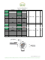
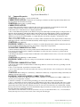
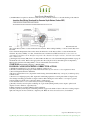
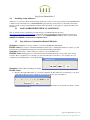
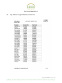
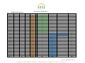
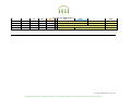
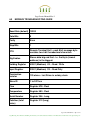
Sage Service Manual-Rev 2
1.0
Remote Wiring Issues
Page 2
2.0
Common Diagnostics
Page 4
3.0
Installing / using Addresser
Page 8
3.1
SAGE ADDRESSER TECHNICAL ASSISTANCE
Page 8
3.2
Sage Addresser Common Installation Difficulties
Page 8
4.0
Sage Addresser Typical Printout (Version 3.14)
Page 11
5.0
MODBUS Prime Registers
Page 12
6.0
MODBUS TROUBLESHOOTING GUIDE
Page 15
Sage Service Manual-Rev 2 Pg 1 of 16
Sage Metering, Inc / 8 Harris Ct / Building D1 / Monterey, CA 93940 / 866-677-SAGE / 831-242-2030 / Fax 831-655-4965 / www.sagemetering.com
Sage Service Manual-Rev 2
1.0
Remote Wiring Issues
The following chart describes the symptoms that will be seen with various open wires
or incorrect wiring relative to remote style meters
Troubleshooting Remote Wiring Issues
mW
Temperature
Normal reading >
60
"80F" or "27C"
Full Scale Reading >
700
"80F" or "27C"
Jbox Wiring Normal Fault
Short between 1 & 2 removed
60
"80F" or "27C"
J-Box
Pin 1
Blue
Open
60
"80F" or "27C"
1&2
Internally
shorted
Pin 2
Green
Open
Pin 3
Red
Open
Short between 4 & 5 removed
J-Box
Pin 4
Orange Open
4&5
Internally
shorted
Flow
0
6300
Response to flow
Yes
Yes
0
0
Yes
Yes
60
"80F" or "27C"
0
Yes
0
183 +
1400 +
"80F" or "27C"
"-201F" or "-129C"
"-201F" or "-129C"
0
240 +
Full Scale
No
Yes
No
Pin 5
Black
Open
180 +
"-201F" or "-129C"
240 +
Yes
Pin 6
SAB Wiring
Pin 1
Pin 2
Pin 3
Pin 4
Pin 5
Pin 6
White
Normal
Red
Green
Blue
White
Black
Orange
Open
600 +
"1434F" or "779C"
Full Scale
No
Open
Open
Open
Open
Open
Open
0
60
60
580
190
1600
"80F" or "27C"
"80F" or "27C"
"80F" or "27C"
"1434F" or "779C"
"-201F" or "-129C"
"-201F" or "-129C"
0
0
0
Full Scale
240 +
0
No
Yes
Yes
No
Yes
No
Sage Service Manual-Rev 2 Pg 2 of 16
Sage Metering, Inc / 8 Harris Ct / Building D1 / Monterey, CA 93940 / 866-677-SAGE / 831-242-2030 / Fax 831-655-4965 / www.sagemetering.com
Sage Service Manual-Rev 2
J-Box 1&2
Internally
shorted
J-Box 4&5
Internally
shorted
J-Box 1&2
Internally
shorted
J-Box 4&5
Internally
shorted
Jbox Wiring
Normal
Miss wired
Pin 1
Blue
Red
Pin 2
Green
Green
Pin 3
Red
Blue
Pin 4
Orange
Orange
Pin 5
Blk
Black
Pin 6
SAB Wiring
Pin 1
Pin 2
Pin 3
Pin 4
Pin 5
Pin 6
Jbox Wiring
White
Normal
Red
Green
Blue
White
Black
Orange
Normal
White
30
91
"80F" or "27C"
Full Scale
No
18
0
+
"-201F" or "-129C"
240 +
Yes
Red
Green
Blue
White
Black
Orange
Pin 1
Blue
Blue
Pin 2
Green
Green
Pin 3
Red
Red
Pin 4
Orange
White
Pin 5
Black
Black
Pin 6
SAB Wiring
Pin 1
Pin 2
Pin 3
Pin 4
Pin 5
Pin 6
White
Normal
Red
Green
Blue
White
Black
Orange
Orange
Red
Green
Blue
White
Black
Orange
Sage Service Manual-Rev 2 Pg 3 of 16
Sage Metering, Inc / 8 Harris Ct / Building D1 / Monterey, CA 93940 / 866-677-SAGE / 831-242-2030 / Fax 831-655-4965 / www.sagemetering.com
Sage Service Manual-Rev 2
2.0
Common Diagnostics
SYMPTOM: Display failure, or pixels extremely dim.
CORRECTIVE ACTION: Contact Factory. Certain types of failures are under long term warranty. Please note
that the 4-20 mA will still function normally.
SYMPTOM: Display fading, or partially fading.
CORRECTIVE ACTION:
a) Some fading, particularly with those characters that are lit up most frequently, is normal. The flow meter will
continue to function properly, and flow meter accuracy and outputs will not be affected.
b) In extreme cases, contact the factory for display replacement.
c) Note, in late 2009, the Sage Prime was modified to incorporate a built-in photocell. The purpose of the photocell is to
adjust the display brightness with ambient lighting. The brighter the surrounding lighting conditions, the brighter the
display. Lower ambient lighting conditions, such as a factory environment, will dim the display. The display will be
dimmest if operated in low ambient lighting, or at night. The photocell circuit is designed to extend the life of the
display, and to minimize fading.
d) Note, in early 2010, a further enhancement was added to further extend the life of the display. The above mentioned
built-in photocell also senses motion which automatically switches display from Screen Saver mode to Normal mode.
SYMPTOM: Erratic Readings.
POSSIBLE CAUSES: If a large Motor or Generator or Variable Frequency Drive (VFD) is nearby the enclosure,
it may be inducing sufficient analog noise into the circuitry to temporarily corrupt the data.
SUGGESTED CORRECTIVE ACTION:
a) If a Power-Restart temporarily solves the problem, than it is likely that the source of the noise was the problem.
b) To prevent subsequent problems, if a Remote Style Meter, move the enclosure as far away as possible from the
source (the Motor or VFD).
c) If an Integral Style Meter, mount the meter in a different location (further from the source) or move the source further
from the meter.
SYMPTOM: Erratic Readings on a Remote Meter.
POSSIBLE CAUSE: In some cases, analog noise is induced into the Remote cable causing erratic, or climbing
readings.
SUGGESTED CORRECTIVE ACTION:
a) Be sure the remote cable is installed in metal conduit and grounded on one end (in some cases, grounding both ends
may be required).
b) Also, avoid coiled cable, especially if not in metal conduit.
c) Also, if extra cable exists, move the extra cable as far away as possible from any source of analog noise, such as large
motors or VFDs.
SYMPTOM: Meter reading zero continuously, or Full Scale continuously, or temperature reading is abnormally low
(hundreds of degrees below zero).
POSSIBLE CAUSES/SUGGESTED CORRECTIVE ACTION:
a) It is likely that a wire is loose. But in rare cases, a sensor could fail (i.e., if a standard sensor, HT01 or HT02 sensor
exceeds a process temperature of 450°F.)
b) Check for continuity to be sure the wiring is making good contact at the terminals of the Junction Box.
c) Also, to verify that the electronics and the sensor serial number are the same, note the following: The sensor’s serial
number will come up upon power up, right after Initializing on the Display. If the serial number doesn't agree with the
Junction Box labels, that would affect calibration (in other words, sensors and electronics are a matched pair—mixing
them up will cause false readings). Also metal Serial Number Tags are fastened to both the electronics and the Junction
Box. They must have identical Serial numbers.
d) To check if a sensor has failed on a remote style meter, it is easy to use the Junction Box to do so. You must Power
Down (shut off power), but you do not need to remove the probe from the pipe.
Sage Service Manual-Rev 2 Pg 4 of 16
Sage Metering, Inc / 8 Harris Ct / Building D1 / Monterey, CA 93940 / 866-677-SAGE / 831-242-2030 / Fax 831-655-4965 / www.sagemetering.com
Sage Service Manual-Rev 2
e) An Ohm Meter is required to check across the sensor leads of the Flow Sensor. Look at the drawing of the Junction
Disconnect the red
Box.
wires on the Factory Side to isolate and measure the resistance. If the reading is infinity or a short, it means that sensor
has failed.
f) Now check the Temperature Sensor. Disconnect the white wires on the Factory Side to isolate and measure the
resistance. If you have infinity or a short, it means that sensor is burned out. Note: Normally the sensors will read
approximately 110 ohms at 70° F. At higher temperatures they should read a higher resistance, but both sensors should
have a similar value.
g) On integral style meters (SIP), there is no Junction Box. In that case, refer to the Prime Integral Terminals on page 19
and check the sensor wires. Remove the appropriate wires first (red pair for flow, then white pair for temperature).
Measure their resistance. If reading infinity or short, it means that sensor has failed.
SYMPTOM: Meter Railing (Pegging) or Reading High
POSSIBLE CAUSES/SUGGESTED CORRECTIVE ACTION:
a) Insufficient straight run (i.e. flow profile is disturbed, causing errors).
b) Possible jet effect if upstream pipe is smaller than meter flow body or if valve is too close upstream to meter.
c) Not following Probe Insertion Guideline.
d) If sensor is inserted in reverse (“Upstream” mark is facing downstream) Meter may over-report (or under-report) by
as much as 30%.
e) If sensor is not aligned properly, with “Upstream” mark facing upstream, a rotation greater than ± 5 degrees may
cause change in reading (greater than ± 5 degrees and less than ± 20 degrees causes meter to over-report; a greater
rotation actually blocks the sensor, and causes meter to under-report).
f) A downstream valve too close to the meter (flow may be reflecting back).
g) Possibly caused by water droplets condensing out of gas stream (which generally causes output to spike; but if
droplets are near continuous, output may rail).
h) Meter is miswired, especially in Remote Style application.
i) Possibly caused by water droplets condensing on inside of pipe wall, which roll down or hit sensor causing output to
spike; but if droplets are near continuous, output may rail. Note: Recommend installation 45° from vertical
Sage Service Manual-Rev 2 Pg 5 of 16
Sage Metering, Inc / 8 Harris Ct / Building D1 / Monterey, CA 93940 / 866-677-SAGE / 831-242-2030 / Fax 831-655-4965 / www.sagemetering.com
Sage Service Manual-Rev 2
j) Possibly caused by water droplets condensing out of gas stream and filling the cavity containing the sensing elements
(usually due to probes mounted below horizontal in saturated pipes).
k) Sensor may be contaminated. Remove probe, wipe off or clean with a solvent. Reinsert.
l) Using a different gas or gas mix than the meter was specified and calibrated for.
m) If a Remote Style Meter (SRP), be sure Serial Numbers of Junction Box and Remote Electronics are identical (if not,
errors in calibration are inevitable). To confirm, verify that Junction Box Serial Number Tag has identical Serial
Numbers
to Tag on Remote Enclosure.
n) Meter may appear to be reading high if user is comparing Sage flow meter readings (SCFM) to an uncorrected
volumetric device (ACFM). For example, at constant volume, a decrease in gas temperature will increase the mass flow
(SCFM). That is completely normal.
SYMPTOM: Reading Low
POSSIBLE CAUSES:
a) Insufficient straight run (i.e. flow profile is disturbed, causing errors).
b) Poor flow profile Upstream (insufficient upstream straight run).
c) Not following Probe Insertion Guideline.
d) If sensor is inserted in reverse (“Upstream” mark is facing downstream) Meter may over-report (or under-report) by
as much as 30%.
e) If sensor is not aligned properly, with “Upstream” mark facing upstream, a rotation greater than ± 5 degrees may
cause change in reading (greater than ± 5 degrees and less than ± 20 degrees causes meter to over-report; a greater
rotation actually blocks the sensor, and causes meter to under-report).
f) Sensor may be contaminated. Remove probe, wipe off or clean with a solvent. Reinsert.
g) Using a different gas or gas mix than the meter was specified and calibrated for.
h) If a Remote Style Meter (SRP), be sure Serial Numbers of Junction Box and Remote Electronics are identical (if not,
errors in calibration are inevitable). To confirm, verify that Junction Box Serial Number Tag has identical Serial
Numbers to Tag on Remote Enclosure.
i) Meter may appear to be reading low if user is comparing Sage flow meter readings (SCFM) to an uncorrected
volumetric device (ACFM). For example, at constant volume, an increase in gas temperature will lower the mass flow
(SCFM).That is completely normal.
j) On most models, the Totalizer will not start counting for 10 seconds after power up so any flow data will not be
accumulated during this time.
k) Insufficient power supply—most products require minimum 100 ma.
Sage Service Manual-Rev 2 Pg 6 of 16
Sage Metering, Inc / 8 Harris Ct / Building D1 / Monterey, CA 93940 / 866-677-SAGE / 831-242-2030 / Fax 831-655-4965 / www.sagemetering.com
Sage Service Manual-Rev 2
l) Excessive load on the 4-20 ma. (To check if problem is due to 4-20 ma output device, temporarily remove device, and
observe if display reads as expected).
SYMPTOM: Totalizer can take up to 10 seconds to update its reading when flow meter is first powered up, or a
channel is changed.
CORRECTIVE ACTION: None. This slight delay is completely normal.
SYMPTOM: Display does not have power
POSSIBLE CAUSE: Miss-wiring
SYMPTOM: 4-20 mA output not tracking the flow rate display
POSSIBLE CAUSE:
a) In normal operation (Self Powered) B4 and B5 must be jumpered to supply power to loop.
b) In Externally Powered mode, the jumper must be removed. Verify that 9 to 27 Volts DC is supplied to externally power
the loop.
Sage Service Manual-Rev 2 Pg 7 of 16
Sage Metering, Inc / 8 Harris Ct / Building D1 / Monterey, CA 93940 / 866-677-SAGE / 831-242-2030 / Fax 831-655-4965 / www.sagemetering.com
Sage Service Manual-Rev 2
Installing / using Addresser
3.0
Addresser is a convenient software kit that includes Addresser software, as well as an optically isolated ULINX RS485
to USB converter. The Addresser is a READ/WRITE Program with drop-down menus for convenient user interface
between your PC or laptop and the Modbus Terminals of the Sage Prime. Contact Sage for ordering information and
instructions.
3.1
SAGE ADDRESSER TECHNICAL ASSISTANCE
Visit our website at www.sagemetering.com and navigate to the Manuals/Download section
(http://www.sagemetering.com/manual.htm). Click on the “Instructional Manuals & Technical Data” button. User
name: sage; password: 7243737. Click on link “Click to View ADDRESSER Procedures” and/or “Click to View
MODBUS Poll/PRIME Communications Setup Instructions”.
3.2
Sage Addresser Common Installation Difficulties
Symptom: LabVIEW error message: Unable to locate the LabVIEW Run-Time Engine
Possible Cause: If you have not installed VI Terminal software prior to installing the Addresser software, you will
be missing the required Run Time Engine that is installed when installing VI Terminal.
Symptom: When trying to run the Addresser program you get a LabVIEW error 8
Probable Cause: This happens most often with users that are running Windows 7 and possible Vista on their
computer. This is a permission error, meaning you do not have the right to write files to your computer. See your
computer Network Administrator to allow this permission
Symptom: Addresser Error, Read Registers Failure:
Possible Cause:
a)
The Slave ID or Mod Bus address of your meter is NOT hex 30. The Addresser is broadcasting to your meter
on Mod Bus Address hex 30 as a default. You can click on the Stop button and then see:
The Addresser can find the slave ID if you click
on the Find Address button.
Sage Service Manual-Rev 2 Pg 8 of 16
Sage Metering, Inc / 8 Harris Ct / Building D1 / Monterey, CA 93940 / 866-677-SAGE / 831-242-2030 / Fax 831-655-4965 / www.sagemetering.com
Sage Service Manual-Rev 2
a.
If you know what address your meter is set to, you can change the address that the Addresser is
talking to by changing the address displayed in the Device Address window of the Addresser.
b.
If the Com Port the Addresser is connected to is different than what the Addresser thinks it is, you
will need to determine what the correct Com Port is.
i. Right click on the My Computer icon, then select Manage
ii. Then select Device Manager followed by Ports (COM & LPT) to find the RS-485 Isolated
Port
Sage Service Manual-Rev 2 Pg 9 of 16
Sage Metering, Inc / 8 Harris Ct / Building D1 / Monterey, CA 93940 / 866-677-SAGE / 831-242-2030 / Fax 831-655-4965 / www.sagemetering.com
Sage Service Manual-Rev 2
iii. When the Read Register Failure message comes up on the Addresser, click on the New Port
button
and then select the
port you just identified.
iv. The Addresser should now talk to your meter.
b) The Baud rate and/or parity of your meter has been set to other than standard of 19200 Baud with Even Parity.
a. You will need to activate the Addresser during the initialization period of the meter during startup.
b. You should be able to communicate with the meter normally now.
Symptom: Windows 7 permission error
Possible Cause: Configuration settings need to be changed to allow the vi to remember what port is assigned
a)
Open the Program Files folder on your computer
a. Highlight Addresser.ini or Configuration settings
b. Right click, then select properties
c. Select Security, then Edit
d. Highlight Users, then change permissions to include Write
e. Click Apply
Sage Service Manual-Rev 2 Pg 10 of 16
Sage Metering, Inc / 8 Harris Ct / Building D1 / Monterey, CA 93940 / 866-677-SAGE / 831-242-2030 / Fax 831-655-4965 / www.sagemetering.com
Sage Service Manual-Rev 2
4.0
Sage Addresser Typical Printout (Version 3.14)
Sage Service Manual-Rev 2 Pg 11 of 16
Sage Metering, Inc / 8 Harris Ct / Building D1 / Monterey, CA 93940 / 866-677-SAGE / 831-242-2030 / Fax 831-655-4965 / www.sagemetering.com
Sage Service Manual-Rev 2
5.0
MODBUS Prime Registers
Registers
bit width
Format
store
8
unit_id
8
mode2
5
pad
1
fix_pt
2
bRun
1
bTotal
1
bEEProm
1
bReset
1
padd
1
bLeadEn
1
bDAClo
1
bDAChi
1
CAL_VAL
bridge[4]
32
k-factor
32
VREF
32
LOAD_RES
32
COEFF A
temp[4]
32
COEFF B
32
COEFF C
32
COEFF D
32
DISP A
disp[4]
32
DISP B
32
DISP C
32
DISP D
32
COEFF A
flow[6]
32
COEFF B
32
COEFF C
32
COEFF D
32
COEFF E
32
byte addr
0
1
2
2
2
3
3
3
3
3
3
3
3
4
8
12
16
20
24
28
32
36
40
44
48
52
56
60
64
68
LabView
0
0
0
0
0
0
0
0
0
0
0
0
0
1
2
3
4
5
6
7
8
9
10
11
12
13
14
15
16
17
hex word addr
256
256
257
257
257
257
257
257
257
257
257
257
257
259
261
263
265
267
269
271
273
275
277
279
281
283
285
287
289
291
IEEE word addr
512
512
513
513
513
513
513
513
513
513
513
513
513
515
517
519
521
523
525
527
529
531
533
535
537
539
541
543
545
547
divide by 1000
<- START ADDR
w/HIGH REG FIRST!
770
772
774
776
778
780
782
784
786
788
790
792
794
796
798
800
802
Sage Service Manual-Rev 2 Pg 12 of 16
Sage Metering, Inc / 8 Harris Ct / Building D1 / Monterey, CA 93940 / 866-677-SAGE / 831-242-2030 / Fax 831-655-4965 / www.sagemetering.com
Sage Service Manual-Rev 2
COEFF F
iir
flow_min
flow_max
temp_min
temp_max
dac1_min
dac1_max
serial
RATE
TOTAL
eng_units
totalizer
ADC0
ADC1
ADC2
ADC3
sil_flow
sil_temp
rtd_mWatts
rtd_res
ref_res_r
ref_res_d
dac_smooth
lead
oheat
bv
fv
tv
adc[4]
32
32
32
32
32
32
16
16
32
32
32
72
76
80
84
88
92
96
98
100
104
108
18
19
20
21
22
23
24
25
25
26
27
293
295
297
299
301
303
305
306
307
309
311
549
551
553
555
557
559
561
562
563
565
567
32
112
28
313
569
32
32
32
32
32
32
32
32
32
32
32
32
32
32
32
32
116
120
124
128
132
136
140
144
148
152
156
160
164
168
172
176
29
30
31
32
33
34
35
36
37
38
39
40
41
42
43
44
315
317
319
321
323
325
327
329
331
333
335
337
339
341
343
345
571
573
575
577
579
581
583
585
587
589
591
593
595
597
599
601
804
806
808
810
812
814
816
818
820
822
824
PLC will access registers from the
High-Order address first (313) and
then will take the previous (312) in
additon (full data contents of the 4 byte
register - 2 bytes/register
828
830
832
834
836
838
840
842
844
846
848
850
852
854
856
858
Sage Service Manual-Rev 2 Pg 13 of 16
Sage Metering, Inc / 8 Harris Ct / Building D1 / Monterey, CA 93940 / 866-677-SAGE / 831-242-2030 / Fax 831-655-4965 / www.sagemetering.com
Sage Service Manual-Rev 2
lv
32
180
45
347
603
using Modbus Poll - Float
Register minus one for value
i.e. Sil_flow = 579 but 578 will give value
Sil_temp will be in 580
860
Sage Service Manual-Rev 2 Pg 14 of 16
Sage Metering, Inc / 8 Harris Ct / Building D1 / Monterey, CA 93940 / 866-677-SAGE / 831-242-2030 / Fax 831-655-4965 / www.sagemetering.com
Sage Service Manual-Rev 2
6.0
MODBUS TROUBLESHOOTING GUIDE
Baud Rate (default) 19200
Data Bits
8
Parity
Even
Stop Bits
1
RTU
Remote Terminal Unit – each 8 bit message byte
contains two 4-bit hexadecimal characters.
Big Endian
Stores data big end first - i.e. first byte (lowest
address) is the biggest.
Holding Register
40001 (Modicon) 4X – Read / Write
Input Register
30001 (Modicon) 3X – Read Only
Termination
resistor
120 ohms – last Prime in a daisy chain
Slave ID
1 to 247 hex
Flow
Register 578 - Float
Temperature
Register 580 - Float
Serial Number
Register 306 - Long
Totalizer (total
value)
Register 312 (long)
Sage Service Manual-Rev 2 Pg 15 of 16
Sage Metering, Inc / 8 Harris Ct / Building D1 / Monterey, CA 93940 / 866-677-SAGE / 831-242-2030 / Fax 831-655-4965 / www.sagemetering.com
Sage Service Manual-Rev 2
Totalizer (broken
down to two 4 bit
characters)
Register 313 * 65536 + Register 312 Total
(signed)
Totalizer zeroing
Write zero to Registers 312 & 313 (signed)
K-factor
Write K-factor to Register 516 (float)
Write (K-factor*1000) to Register 772 (long)
Modbus
Address (ID)
Register 256 (Hex) 305A is address 30 write
315A to register 256 for address 31 (NOTE: 5A
must not be touched!)
Must use function 16 multiple registers
Engineering Units
(Rate String)
Engineering Units
(Total String)
ASCII – Registers 308 & 309 – HEX
SCFM would be - (308) 53-S 43-C (309) 46-F 4D-M
Will be written 0x4353 (308) and 0x4D46 (309)
ASCII – Registers 310 & 311 – HEX
SCF (degF) would be (310) 53S 43C (311) 46F 46F (deg)
Will be written 0x4353 (310) and 0x4646 (311)
SCF (degC) would be (310) 53S 43C (311) 46F 43C (deg)
Will be written 0x4353 (310) and 0x4346 (311)
Sage Service Manual-Rev 2 Pg 16 of 16
Sage Metering, Inc / 8 Harris Ct / Building D1 / Monterey, CA 93940 / 866-677-SAGE / 831-242-2030 / Fax 831-655-4965 / www.sagemetering.com