1
A Higher Level of Precision…
A Higher Level of Performance
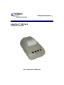
Intell-Print™ OM-192-S
Dot Matrix Printer
User Operation Manual
1
1. INTRODUCTION
OM19X is a dot matrix impact printer that is available in 24 column, OM190,
and 40 column, OM192, models. It is compact and reliable with a variety
of features and options suitable for a wide array of applications including
medical and industrial instruments, point of sale, test and measurement,
security, time and attendance, etc.
1.1 Features
Easy paper loading and ribbon replacement
Serial RS-232C or Centronics parallel
Multiple international character set
Auto power off features.
User selectable options stored in non-volatile ram.
Watch dog software shuts off power to the print head and carriage motor in a
paper jam situation.
Full 96 ASCII set (plus additional European/Chinese and scientific
characters).
32kbyte buffer.
Double width printing.
Double height printing.
Underlining.
Built-in tab stops.
Vertical tab.
Form feed.
Self-test.
Inverted printing (data mode only).
Graphics.
Reset command.
Software diagnostic mode.
DH technology 1000 emulation.
Epson ESC/POS emulation.
Citizen 560 emulation.
2
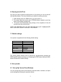
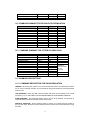
2. SPECIFICATIONS
2-1. General specifications.
Model
Print method
No. of columns
Printing speed
No. of dots per
line
Dot Size
Character
size
(mm)
Line Spacing
Font size
Interface
Emulation
Data buffer
Ink ribbon
Paper
No. of copies
Power supply
Dimensions (mm)
Reliability (MCBF)
Weight
Safety approvals
Operating
condition
OM190
OM192
Shuttle impact dot matrix (8 pins)
24
40
2.5 lps
1.7 lps
144
240
0.33 (H) x 0.38 (W) mm
1.7 (W) x 2.6 (H)
1.1 (W) x 2.6 (H)
3 dot lines
(5+1) x 7
Type S: RS-232C serial
Type P: Centronics parallel
Epson ESC/POS, Citizen 560,
DH1000
1 KB
ERC-09 or ERC-22 (Purple or black)
Width
57.5 0.5 mm
Diameter
60 mm (Max)
Original + 1 copy
9 VDC 10% 2.0 A
178 (L) x 105 (W) x 82 (H)
1.5 million lines
0.9 million lines
400 g or 0.88 lbs
CE
0 to 50
C 10 to 80 % RH
(Operating)
2-2. Printer types and models:
Printer types and models are selected according to the following designation:
OM19X - Y - Z
X: Designates column capacity:
Y: Designates interface type
2
0
24 columns
40 columns
S
P
Serial interface
Parallel interface
3
Z: Designates input voltage for the external power adaptor
Blank 110VAC
WA
Without adaptor
220
220 –240 VAC
SMPS 90-240VAC
3. Setting up the printer
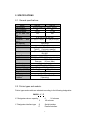
3-1. Unpacking.
The items illustrated below are included with your printer. If any items are
damaged or missing, please contact your dealer for assistance.
Printer, Paper Roll, Power Supply, Ribbon (installed), Manual, and Interface
Cable.
Printer
Paper roll
Power Adapter
Interface Cable
3-2. Selecting a Place
4
1. Protect your printer from excessive heat such as direct sunlight or
heaters.
2. Avoid exposing the printer to excessive dust and humidity.
3. Place the printer on a firm, level surface free from intense vibration or
shock.
3-3
Connecting the Power Adapter
This printer requires an external power supply. Be sure to use a power supply
that matches the specifications.
1.
2.
3.
4.
Make sure the power switch is OFF.
Insert the output plug of the power adapter into the DC jack of the printer.
Plug the adapter or the power supply’s cord into an outlet.
For best results use one of the following Omniprint adapters:
OMPS190-915-NA
(120VAC input)
OMPS190-915-EU
(220-240VAC input)
OMPS190-915-SMPS (90-240VAC input)
Output: 9VDC 1.5A , 2.1mm x 5.5mm female plug , Center positive
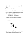
3-4
Connecting the Interface Cable
You need an appropriate serial interface or parallel interface cable to connect
your computer to the printer.
3-4-1
Serial Interface Cable: OM19-S
1. Make sure that both the printer and computer are turned off.
2. The serial printer comes with a DB-25 female connector. Plug the DB-25
male end of the cable into the printer connector, as shown above.
5
3. Use a screw driver to fasten the cable screws to the two nut screws
installed on the printer connector.
4. Connect the other end, DB9-F connector, to your computer.
5. Use Omniprint part number:
CBL-625F-25M
(DB-25 male on the host side)
CBL-69F-25M
(DB-9 male on the host side)
3-4-2
Parallel Interface Cable: OM19-P
1. Make sure that both the printer and computer are turned off.
2. The parallel printer comes with a DB-25 male connector. Plug the DB-25
female end of the cable into the printer connector, as shown above.
3. Use a screw driver to fasten the cable screws to the two nut screws
installed on the printer connector.
4. Connect the other end, DB25-M connector, to your computer.
5. Use Omniprint part number:
CBL-625M-25F-STR
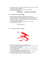
3-5
Installing the Ribbon Cartridge
1. Turn the printer off before you open the printer cover.
2. Remove the old ribbon by pressing on the front right hand corner of the
cassette where marked “PUSH”.
3. Turn the ribbon cassette’s knob in the direction of the arrow to take up
any slack in the ribbon.
4. Insert the ribbon between the printer head and platen, as shown above,
and push the cassette down until it snaps in place.
5. Turn the knob a few times again to take up any slack in the ribbon.
6. Use the following part number for ordering new ribbons:
6
Regular
Long Life
ERC-09-
ERC-22-
( P for purple or B for black)
( P for purple or B for black)
©
3-6
Loading Paper
Use a paper roll that meets the specifications. Do not use paper rolls that are
glued to the core. Make sure data is not being transmitted to the printer while
loading paper.
``````
PUSH
ribbon
change
1. Cut the leading edge of the paper roll straight at a right angle, as shown
above.
2. Remove the old paper roll, if any, and press the FEED button until any
excess paper left in the mechanism is out. Do not pull the paper out of
the printer mechanism paper inlet.
3. Mount the paper roll on the paper roll holder by gently bending the plastic
tab, on the right, and insert the roll so that the holes in the core align with
the axes of the paper roll holder. Make sure that the two holders are
completely inside the core so that the paper roll can move freely without
much friction, i.e. the core inside diameter is larger than the paper roll
holder’s outside diameter.
7
4. Hold the both edges of the paper and insert it straight into the paper slot.
5. Press the FEED button until approximately two inches of paper is fed
through the mechanism.
6. Tear the excess paper against the serrated edge and close the cover.
7. Use the following Omniprint part number to reorder paper:
PP-225-135
PP-225-90WC
4.
1 ply paper roll
2 ply paper roll
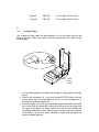
External Appearance.
Cover top
Paper cover
Roll
Roll
paper
paper
Control panel
Paper roll holder
Top cover
Bottom cover
On
Off
8
Interface connector DC Jack
5. Control Panel
The control panel features four buttons and one LED to indicate printer status.
ON BUTTON: Press the ON button to power up the printer. A red LED inside
the button will light up. The printer goes ON LINE ready to receive data from the
host.
OFF BUTTON: Press the OFF button once to turn the power OFF.
FEED BUTTON: When the FEED button is pressed and then released within
0.5 sec., the paper feeds only one line. When the FEED button is held
depressed for more than 0.5 sec., the paper feeds continuously.
SEL BUTTON: The SEL button is used to change the printer setting. (Please
refer to the SET UP section for details)
STATUS LED: The LED is located inside the ON button and lights up when
power to the printer is on. The LED flashes every second when the printer head
jams and every 0.2 second in the case of mechanism malfunction.
9
6. Running the Self Test
Any time you want to check the performance of your printer you can run the self
test described below. This shows whether your printer is working correctly.
1. While holding down the FEED button, turn the printer on.
2. The printer prints the model name, EPROM revision installed, and a few
lines of the rotating character set.
3. The printer will automatically stop printing at the completion of the self
test and enter the normal mode.
NOTE: THE PRINTER WILL GO OFF LINE AND WILL NOT COMMUNICATE
WITH THE HOST WHILE IT IS IN SELF TEST MODE.
7. Default settings
Your printer is supplied with the following default setting.
DATA BITS
PARITY
BAUD RATE
CHARACTER SET
PRINT MODE
AUTO-OFF
EMULATION
DTR
INTERFACE
8
NONE
9600
U.S.
TEXT
5MIN
STANDARD
(ESC/POS)
NORMAL
SERIAL
The factory default settings can be restored by simultaneously pressing the
FEED and SEL buttons at power up. Releasing the FEED button before the SEL
button will save the revised settings.
8. Set-up mode
8.1 Set-up By Control Panel Buttons
You can change the printer serial interface, character table, emulation, and print
mode settings by following the procedure below:
10
1.
By turning the power on while pressing the SEL button the printer will
print the current configuration and get in SET-UP mode.
2.
The power LED will flash every second to indicate the printer is in SETUP mode.
3.
By pressing the FEED button, in SET-UP mode, you can scroll through
the printer parameters in the order shown in the table below.
4.
Pressing the SEL button will cause the setting of a parameter to
change in the sequence shown below.
5.
Once the desired setting is selected, it can be saved by pressing the
SEL button while pressing the FEED button.
NOTE: IF NO BUTTONS ARE PRESSED FOR 15 SECONDS, THE SET-UP
MODE IS AUTOMATICALLY TERMINATED WITHOUT CHANGING THE
ORIGINAL PARAMETERS.
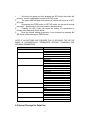
PARAMETER (FEED Button)
NUMBER OF DATA BITS
SERIAL PARITY
SERIAL BAUD RATE
CHARACTER SET
PRINT MODE
AUTO POWER OFF
EMULATION
DTR
STATUS (SEL Button)
8BIT DATA
7BIT DATA
NO PARITY
ODD PARITY
EVEN PARITY
2400 BAUD
4800 BAUD
9600 BAUD
19200 BAUD
U.S.A.
FRANCE
GERMANY
U.K.
DENMARK I
SWEDEN
ITALY
SPAIN
JAPAN
NORWAY
DENMARK II
TEXT(NORMAL PRINT)
DATA(INVERTED PRINT)
5MIN
1MIN
DISABLE
STANDARD(DH1000)
CITIZEN 560
ESC/POS
NORMAL
INVERTED
8.2 Set-up Through the Data Port
11
If the printer is turned on while pressing the SEL and FEED buttons,
simultaneously, and only the SEL button is released, the printer will print : “nvr
comms ready>”
At this point the printer is waiting to receive data in the following format : SETUP mode + Carriage Return +n1+…n10
(n1 to n10 are hex number) the SET-UP mode followed by a carriage return
indicates that the printer should expect parameter data as shown in the table
below.
Upon receiving information in the correct format, the printer will print : “data
ok,nvr updated !”.
Note : If no data is received within 15 seconds or the FFED button is released
before the procedure is complete, then the new setting will not be saved and the
printer will print : “set error nvr unchanged “.
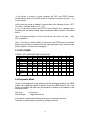
8.3 NVR COMMS
STRING “ SET-UP MODE”,ODH,N1,N2,N3,N4…..
0
7
EVEN
19200
1
8
ODD
9600
2
3
NONE
4800
2400
Denmark2
Norway
Japan
Spain
Print mode
Auto off
Emulation
DATA
Disable
TEXT
1MIN
560
5MIN
8
Printing
Invert
9
10
Zero Status
Reverse
future
1
2
3
4
Data bit
Parity
Baud rate
Country
5
6
7
ESC/PO
S
4
5
6
7
8
9
10
Italy
Swede
n
Denmark
I
U.K.
German
y
Franc
e
U.S.A.
Standar
d
Norma
l
8.4 Diagnostic Mode
To get in the diagnostic mode, perform self-test and keep pressing the FEED
button until “diagnostic modes” is printed. Press the FEED button to end. The
power-on indicator will flash every two seconds. Following is an example of the
diagnostic mode:
Abc de fg
…….normal print
Abcide nfogm ……diagnostic print out
In the above example the following sequence of characters was sent :
Character f, single width(o),character g, carriage return(m).
12
9. Accessories
1) Paper: 57.5mm+/-0.5mm(width) , 60mm max(roll diameter) , 85 microns
(thickness)
PP-225-80
1-ply paper roll
PP-225-75WC 2-ply paper roll
2) Ribbon specification :
ERC-09 P (Purple) or B (Black) Standard
cartridge
ERC-22 P (Purple) or B (Black) Long Life Cartridge
3) Interface Cable: 6 foot long, shielded cable with molded connectors.
CBL-625M-25F-STR Parallel cable
CBL-625F-25M
Serial cable w/ DB-25F host
side
CBL-69F-25M
Serial cable w/ DB-9F host side
4)Power Supply: Output: 9VDC 1.5A , 2.1mm x 5.5mm female plug , center
positive.
OMPS190-915-NA
120VAC input
OMPS190-915-EU
220-240VAC input
OMPS190-915-SMPS 90-240VAC input
10. Troubleshooting
1) IF THE POWER LED DOES NOT COME ON.
Make sure the power supply cables are securely plugged into the printer, the
adapter, and the power outlet. Also, make sure that power is supplied to the
power outlet. If the outlet is controlled by a switch or timer, use another outlet.
1)IF THE POWER LED IS ON BUT PAPER DOES NOT FEED.
This may be a head jam condition, first turn off the printer and make sure there
is no paper stuck in the mechanism; however do not use force or a sharp object
to remove the jammed paper.
2)IF THE PAPER IS NOT FEEDING PROPERLY.
If the printout looks squashed, make sure that the paper roll moves freely on the
paper holder. If the paper is wrinkled on the edges, the roll may not loaded
correctly. In that case remove the paper and reload.
4) IF THE PRINTER SOUNDS LIKE IT IS PRINTING BUT NOTHING IS
13
PRINTED
Make sure a ribbon cartridge is installed properly that is not worn out. Please
note that the ribbon needs to be in front of the paper.
If the printout is faint, turn the knob on the cartridge in the direction of the arrow.
Also, see if the knob turns when the FEED button is pushed, if it does not, then
the advance gear on the ribbon or the mechanism may be defective or worn out.
3)IF THE PRINTER DOES NOT COMMUNICATE WITH THE HOST.
Run the self test to check that the printer works properly. If the self test does not
work contact your dealer or qualified service person. If the self test works
properly, check the following:
A. You are using the right interface cable.
B. The connection on both ends of the cable between the printer and
the host.
C. The data transmission setting may be different between the printer
and the host. Use the SET-UP instructions to change the settings, if
necessary.
4)IF A LINE OF DOTS IS MISSING IN THE PRINTOUT.
The print head may be damaged. Contact your dealer or qualified service
person.
11. Interface connections
The OM19printer is available in RS-232C serial and Centronics compatible
parallel versions. The interface type is printed on the self-test printout. The
connector for the serial interface is a DB25 female and male for parallel.
11-1. SERIAL INTERFACE
11-1-1 Serial Interface Specifications
Data Transmission Method:
Baud Rate:
Word Length:
Signal Polarity:
Asynchronous serial interface
User selectable from 2400, 4800, 9600, 19.2K
Start bit
1 bit
Data bit
7 or 8 bit
Parity
Odd, Even, None
Stop bit
1 bit
MARK: Logic “1” (-10V)
SPACE: Logic “0” (+10V)
14
Input Control (DTR signal) :
Mark: Data transmission not possible
Space: Data transmission possible
11-1-2 Connector Pin Assignment
FUNCTION
RXD
TXD
CTS
RTS
DSR
GND
*POWER
NC
F-GND
DTR
PIN NUMBER
3
2
5
4
6
7,9,14
12,13,16
5,6,8,10,11,15,17-19,2125
1
20
INPUT-OUTPUT
IN
OUT
IN
OUT
IN
IN
OUT
* Please note that some models can be set at the factory to receive power through the
serial port.
11-1-3
Serial Interface Timing Diagram
11-2. PARALLEL INTERFACE
11-2-1 Parallel Interface Specifications
Data Transmission Method:
Synchronization:
Handshaking:
Data Transfer Rate:
Logic Level:
8 bit parallel, DATA0 – DATA7
Via external STROBE pulses
ACK and BUSY signals
1000 to 6000 characters per second
Compatible with TTL level
11-2-2 Parallel Connector Pin Assignment
15
PIN
1
2
3
4
5
6
7
8
9
10
11
12
13
FUNCTION
STROBE
DATA 0
DATA 1
DATA 2
DATA 3
DATA 4
DATA 5
DATA 6
DATA 7
ACK
BUSY
N.C.
N.C.
PIN
14
15
16
17
18
19
20
21
22
23
24
25
FUNCTION
N.C.
N.C.
N.C.
N.C.
N.C.
+9V
+9V
GND
GND
GND
GND
GND
Printer is capable of receiving data from the host while the BUSY signal is in the
LOW state and communication will be interrupted when the signal is HIGH>
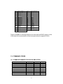
12. COMMAND CODES
12.1 COMMAND SUMMARY FOR DH1000 EMULATION
FUNCTION
HORIZONTAL TAB
LINE FEED
FORM FEED
VERTICAL TAB
CARRIAGE RETURN
DOUBLE WIDTH
SINGLE WIDTH
RESET
UNDERLINE
UNDERLINE RELEASE
KEYSTROKE
CTRL I
CTRL J
CTRL K
CTRL L,n
CTRL M
CTRL N
CTRL O
CTRL Q
CTRL U
CTRL X
16
HEX
09H
0AH
0BH
0CH,n
0DH
0EH
0FH
11H
15H
18H
DECIMAL
9
10
11
12,n
13
14
15
17
21
24
REVERSE PRINT
DOUBLE HEIGHT
GRAPHICS
CTRL Y
CTRL Z
CTRL [,n
19H
1AH
1BH, n
25
26
27,n
12.2 COMMAND SUMMARY FOR EPSON ESC/POS EMULATION
FUNCTION
HORIZONTAL TAB
LINE FEED
FORM FEED
CARRIAGE RETURN
SET PRINT MODE
INITIALIZE PRINT
CHARACTER SET
PRINT & FEED
STATUS REQUEST
INVERTED PRINTING
SET FORM LENGTH
KEYSTROKE
CTRL I
CTRL J
CTRL L
CTRL M
ESC ! n
ESC @
ESC R n
ESC d n
ESC v
ESC { n
ESC C n
HEX
09H
0AH
0CH
0DH
1BH,21H,n
1BH,40H
1BH,52H,n
1BH,64H,n
1BH,76H
1BH,7BH,n
1BH,43H,n
DECIMAL
9
10
12
13
27,33,n
27,64
27,82,n
27,100,n
27,118
27,123,n
27,67,n
12.3 COMMAND SUMMARY FOR CITIZEN 560 EMULATION
FUNCTION
LINE FEED
FORM FEED
CARRIAGE RETURN
REVERSE PRINT
CLEAR BUFFER
GRAPHIC PRINT
PAGE LENGTH/FORMAT
PAGING IS OFF
2.75MM SPACING
5.5MM SPACING
DOUBLE WIDTH
SINGLE WIDTH
KEYSTROKE
CTRL J
CTRL L
CTRL M
CTRL T
CTRL X
ESC K
ESC C
ESC 0
ESC1
ESC 2
HEX
0AH
0CH
0DH
14H
18H
1BH,4BH
1BH,43H
1BH,4FH
1BH,31H
1BH,32H
1EH
1FH
DECIMAL
10
12
13
20
24
COMMANDS
ACKNOWLEDGED
BUT NOT
EXECUYED
30
31
11.2 COMMAND DESCRIPTIONS
11.2.1 COMMAND DESCRIPTION FOR DH1000 EMULATION
TAB(09H) : Moves the print position to the nest horizontal tab position. The default tab positions
are at every 8 character intervals. This command will be ignored unless the nest horizontal tab
position is set.
LINE FEED(0AH) : Prints the data in the print buffer and feeds one line based on the current
line spa cing . IF LF+CR IS SENT, CR WILL BE IGNORED TO AVOID DOUBLE FEEDING.
FORM FEED(0BH) : The printer fast feeds to the top of form set by software. Any character in
the buffer will be printed and the buffer pointer will be reset.
VERTICAL TAB(0CH,N) : Printer feeds the paper by N lines. N is a single byte hex number in
the 0<n<20h range. Note that a vertical tab will print the contents of the line buffer before being
executed.
17
CR(0DH) : This command prints the data in the print buffer and feeds one line. If a LF is sent
immediately after CR, it will be ignored to avoid double printing. When the line buffer is full, ie
th
th
upon receiving the 24 and 40 characters in the case of OM190 and OM192, respectively, the
printer will automatically print the data in the buffer. If CR or LF is sent, they will be ignored in
this situation.
DOUBLE WIDTH(0EH) : Upon receiving this command the printer will go in the double wide
mode and remains in this mode until terminated by the single wide command or completion of
the current line. If the last character of a line is double wide but there is room only for a single
wide character, it will be printed in single width.
SINGLE WIDTH(0FH) : Printer reverts back to single width printing. Single and double wide
characters can be combined anywhere on a line.
RESET(11H) : This commands causes the printer to be set to power up default conditions.
NOTE THAT THIS WILL NOT CLEAR THE BUFFER OF ANY DATA PREVIOUSLY SENT.
UNDERLINE(15H) : Characters sent after this command will be underlined. Tabs are not
underlined. Underlining is terminated by the underline release command or upon completion of
the current line.
UNDERLINEL RELEASE(18H) : Terminates the underline mode.
REVERSE PRINT(1AH) : This command causes the printer to print white on black. You can
toggle between reverse and normal anywhere on a line but the reverse print mode will
automatically be terminated at the end of a line.
DOUBLE HEIGHT(1AH) : Upon receiving this command the printer will go in the double high
mode and re mains in this mode until terminated by the single wide command or completion of
the current line.
NOTE THAT DOUBLE HEIGHT AND SINGLE HEIGHT CHARACTERS CANNOT BE
COMBINED ON THE SAME LINE.
GRAPHICS(1BH,N) : This command causes the printer to go in the bit image printing mode.
The number of graphic bytes sent will depend on the type of mechanism. For each graphic byte
sent to the printer, 6 out of 8 bits are used to form the graphic string (LSB is the right most dot).
N is the number of times the string will be repeated for a repetitive pattern, 0N255 lines. The
print buffer will be printed first if not empty.
EXAMPLE : TO REPEAT A STRING OF DATA BYTES,D1----D24 OVER TWO ROWS FOR
OM190: SEND : 1BH,D1-------------D24. FOR A NON-REPEATED STRING SEND :1BH,01H,D1---D24.
11.2.2 EPSON ESC/POS COMMAND DESCRIPTION
TAB(09H) : : Moves the print position to the next horizontal tab position. The default tab
positions are at every 8 character intervals. This command will be ignored unless the nest
horizontal tab position is set.
LINE FEED(0AH) : Prints the data in the print buffer and feeds one line based on the current
line spacing . IF LF+CR IS SENT, CR WILL BE IGNORED TO AVOID DOUBLE FEEDING.
FORM FEED(0CH) : Prints the current line and feeds the number of lines programmed by using
the ESC C command.
18
CR(0DH) : This command prints the data in the print buffer and feeds one line. If a LF is sent
immediately after CR, it will be ignored to avoid double printing.
ESC ! n(1BH,21H,n) : Sets the print mode according to the following table. n is a single byte in
which each bit sets the printing function. Note that underline cannot be used with a horizontal
tab and any combination of double height and width can be used. Default is n=0.
Bit
Off/On
Hex
0,1,
2
---
---
Decim
al
---
Off
00
0
Off
On
Off
On
00
10
00
20
--00
80
0
16
0
32
3
4
5
6
--Off
On
7
--0
128
Function
Undefined
Emphasized mode
off
Double-height off
Double-height on
Double-width off
Double-width on
Undefined
Underline mode off
Underline mode on
ESC @(1BH,40H) : Initialize the printer. Clears the print buffer and resets the printer to default
values.
ESC R n(1BH,52H,n) : Selects the international character set form the following table
n
0
1
2
3
4
5
6
7
8
9
10
Character set
U.S.A.
France
Germany
U.K.
Denmark I
Sweden
Italy
Spain
Japan
Norway
Denmark II
ESC d n(1BH,64H,n) : Prints the data in the print buffer and feed n lines.
ESC v(1BH,76H) : The current printer status is transmitted to the host upon receipt of this
command. The printer transmits one byte of data to the host indicating the status of the paper
out detector. It takes the form of a single byte which is fixed at 0(to indicate paper in) for printer.
The Byte is sent regardless of the CTS handshaking signal.
ESC { n(1BH,7BH,n) : Inverted print command. If n=1 then printing will be is inverted and text
will be printed from right to left. For normal printing n=0. The default mode is set by the
programmed
parameters in the printer.
ESC C n(1BH,43H,n) : Set form length. When used in conjunction with the form feed
command(0ch), the printer will feed n lines. NOTE THAT IF n=0,THEN THERE WILL BE NO
LINE FEED.
19
11.2.3 COMMAND DESCRIPTION FOR CBM560 EMULATION
LINE FEED (0AH) : Prints the data in the print buffer and feeds one line.
FORM FEED(0CH) : Form feeds after printing. This is fixed at three lines.
CR(0DH) : Feeds a new line after printing.
REVERSE PRINT(14H) : This command causes the printer to print white on black. You can
toggle between reverse and normal anywhere on a line but the reverse print mode will
automatically be terminated at the end of a line.
CLEAR BUFFER(18H) : All the data in the print buffer, received prior to this command, will be
cleared; however, this code is treated as data in the graphics mode.
DOUBLE WIDTH(1EH) : Upon receiving this command the printer will go in the double wide
mode and remains in this mode until terminated by the single wide or LF command or
completion of the current line. If the last character of a line is double wide but there is room only
for a single wide character, it will be printed in single width.
SINGLE WIDTH(1FH) : Printer reverts back to single width printing. Single and double wide
characters can be combined anywhere on a line.
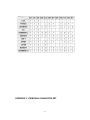
APPENDIX 1. INTERNATIONAL CHARACTERS SET
20
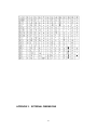
APPENDIX 2. PRINTABLE CHARACTER SET
21
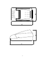
APPENDIX 3. EXTERNAL DIMENSIONS
22
23