1
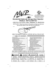
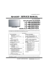
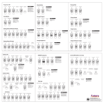
READ THIS MANUAL CAREFULLY
BEFORE BEGINNING INSTALLATION
831E COMMERCIAL
RECEIVER
INSTRUCTIONS
MODELS:
• 831E
• 831E MASTER & SLAVE UNITS
PRODUCT FEATURES
Allstar 831E Commercial Receivers are designed to work with most commercial door operators. The 831E is connected to the
commercial operator in the same manner as a 3-button station and provides open, close and stop functions via radio control. The
receiver is powered from the operator’s 24 VAC transformer. The antenna is removable and may be moved (using coaxial cable) to a
new location for better RF reception. When receivers have to be installed in close proximity to each other (such as Fire Stations),
master/slave units may be used to reduce the potential for receiver cross-talk.
IMPORTANT INSTALLATION NOTES
WARNING
TO REDUCE THE RISK OF SEVERE INJURY OR DEATH:
READ AND FOLLOW ALL INSTALLATION INSTRUCTIONS!
•
ALLSTAR 831E RECEIVERS ARE INTENDED FOR
USE WITH COMMERCIAL DOOR OPERATORS
ONLY. DO NOT USE FOR ANY OTHER PURPOSE.
DO NOT MODIFY IN ANY MANNER.
•
CHECK LOCAL BUILDING AND ELECTRICAL
CODES FOR MANDATORY INSTALLATION AND
WIRING REQUIREMENTS.
•
CONNECT POWER CORDS ONLY TO A PROPERLY
GROUNDED OUTLET. IF PERMANENT WIRING IS
REQUIRED BY CODES, DISCONNECT POWER AT
FUSE BOX OR CIRCUIT BREAKER BEFORE
ATTEMPTING ANY WIRING CONNECTIONS.
•
DO NOT WEAR RINGS, WATCHES OR LOOSE
CLOTHING WHILE INSTALLING OR SERVICING
GARAGE DOOR OPENERS.
WEAR SAFETY
GOGGLES OR OTHER PROTECTIVE EYEWEAR.
•
AN UNBALANCED DOOR OR ONE THAT STICKS OR
BINDS MAY CAUSE INJURY OR DEATH. ENSURE
DOOR IS PROPERLY BALANCED AND ELIMINATE
ANY STICKING OR BINDING.
•
YOUR GARAGE DOOR IS A LARGE MOVING
OBJECT. THE SPRINGS, PULLEYS, CABLES AND
MOUNTING HARDWARE UTILIZED TO BALANCE
ITS OPERATION ARE UNDER EXTREME TENSION
AT ALL TIMES AND CAN CAUSE SERIOUS
PERSONAL INJURY, EVEN DEATH, IF DISTURBED.
ONLY A QUALIFIED SERVICE PERSON SHOULD
MOVE, LOOSEN OR ADJUST DOOR SPRINGS OR
HARDWARE.
•
LOCATE CONTROL PUSHBUTTONS WITHIN SIGHT
OF THE DOOR AND AWAY FROM THE MOVING
PARTS OF THE DOOR. INSTALL ENTRAPMENT
WARNING LABEL NEXT TO THE CONTROL
PUSHBUTTON IN A PROMINENT LOCATION.
•
REMOVE ALL ROPES AND REMOVE OR MAKE
INOPERATIVE ALL LOCKS CONNECTED TO THE
GARAGE DOOR.
•
THE
IMPORTANT
SAFEGUARDS
AND
INSTRUCTIONS IN THIS MANUAL CANNOT COVER
ALL POSSIBLE CONDITIONS AND SITUATIONS. IT
MUST BE UNDERSTOOD THAT COMMON SENSE
AND CAUTION MUST BE EXERCISED BY THE
PERSON(S) INSTALLING, MAINTAINING AND
OPERATING THIS EQUIPMENT.
INSTALLER: Leave this manual with your customer upon completion of the installation.
Page 1 of 4
P/N 106547 REV D
831E COMMERCIAL RECEIVER WIRING INSTRUCTIONS
WARNING
IMPROPER WIRING COULD CAUSE ELECTROCUTION OR DAMAGE TO CIRCUITRY.
FOLLOW LOCAL BUILDING AND ELECTRICAL CODES.
DISCONNECT POWER AT FUSE BOX AND DOOR OPENER
WARNING TO PREVENT ELECTROCUTION
BEFORE WIRING PERMANENTLY.
105113
TO OPERATOR
Y
TERMINAL STRIP
24 VAC
GRA
GE
STOP
OR
AN
CLOSE
BLACK
OPEN
Typical 4-wire 3-button stations are wired as
shown in Figure 2. Number 18 gauge wire
or heavier must be used for wiring the
control stations and the 831E receiver to the
door operator. Smaller gauge wire may
cause operational problems, especially when
multiple 3-button stations are used. For
typical installations the 831E receiver is
mounted near the door operator, away from OPEN CLOSE
any high voltage conduits or steel support
beams. For wiring, follow the steps below
and refer to Figure 3.
W
HI
TE
WALL PUSHBUTTON STATION
RE
D
The 831E receiver functions as a 3-button station. Three sets of isolated contacts
are provided; normally open contacts for the OPEN PUSHBUTTON (orange
wires); normally open contacts for the CLOSE PUSHBUTTON (black wires);
normally closed contacts for the STOP PUSHBUTTON (gray wires). Refer to
Figure 1. For special STOP circuit applications, normally open contacts are
available from the factory.
STOP
Figure 2
1. In the door operator control panel,
locate the wire connecting the door
operator to the 3-button station
COMMON. Note its location and
remove.
2. Connect one of the gray wires from the
831E to the wire just removed from the
pushbutton COMMON.
106549
Step 5
Step 3
MVP-831E
831E
RECEIVER
RECEIVER
WALL PUSH
BUTTON
STATION
COMMERCIAL
OPERATOR
STOP COM
OPEN
CLOSE
OPEN
Step 4
CLOSE
STOP
COMMON
3. Connect the following wires from the
831E to the operator 3-button
COMMON (as shown at right):
ONE ORANGE (OPEN)
ONE BLACK (CLOSE)
ONE GRAY (STOP)
ORANGE
BLACK
GRAY
BLACK
GRAY
Step 2
Figure 3
Removed Wire
(See Step 1)
WHITE
4. Connect the remaining 831E black wire
to the CLOSE pushbutton terminal in
the door operator control panel.
RED
ORANGE
24 VAC
Step 6
5. Connect the remaining 831E orange
wire to the OPEN pushbutton terminal in the door operator control panel.
6. Finish the wiring by connecting 24 VAC to the red and white wires of the 831E receiver.
BEFORE APPLYING POWER, CHECK ALL CONNECTIONS AND INSTALL THE ANTENNA.
WARNING
DO NOT USE RADIO CONTROLS ON COMMERCIAL DOOR OPERATORS UNLESS PROPER
ENTRAPMENT PROTECTION DEVICES ARE INSTALLED. CONSULT THE MANUFACTURER OF
YOUR OPERATOR FOR MORE DETAILS.
Page 2 of 4
P/N 106547 REV D
COMMERCIAL RECEIVER & TRANSMITTER CODING INSTRUCTIONS
The 831E receiver may be used with many different Allstar transmitters. The information below indicates how to set the coding
switches in the various transmitters and the 831E receiver.
TRANSMITTER
RECEIVER
IF YOU ARE USING A 8831 OCS-ECONOMY OR 831 STANDARD
A-B-C Selector Coding Switch
TRANSMITTER:
Switch Position
#6
Exactly match all 8 code switches in the transmitter and receiver. The code switches
A
+
may be set in any random pattern of +, - and 0.
B
0
IF YOU ARE USING A 8831C OCS-ECONOMY OR 733 STANDARD
TRANSMITTER:
C
-
These transmitters are used to control up to 3 different doors. This is accomplished by setting the selector switch on the transmitter to
either A, B & C and setting the #6 coding switch in the 831E receiver .
Start coding by exactly matching all 8 code switches in the transmitter and the receivers. The code switches may be set in any random
pattern of +, 0 and - positions. Next, in receiver A, set code switch #6 to the + position; In receiver B set code switch # 6 to the 0
position; In receiver C set code switch # 6 to the - position. The table to the right shows the switch positions.
IF
YOU ARE USING A
639 STANDARD TRANSMITTER:
This transmitter is used to control up to 9 different doors. This is
accomplished by setting the selector switch on the transmitter to
either 1, 2, 3, 4, 5, 6, 7, 8 or 9 and setting the #7 and #8 coding
switches in the 831E receiver.
Start coding by exactly matching all 8 code switches in the
transmitter and receivers. The code switches may be set in any
random pattern of +, 0 and - positions. Next, in receiver 1, set
code switch #7 to + and code switch #8 +; In receiver 2, set code
switch #7 to + and code switch #8 to 0. Continue setting the
codes in the 831E receivers as shown in the table.
IF
YOU ARE USING A
53S STANDARD TRANSMITTER:
This transmitter is used to control up to 27 different doors. This is
accomplished by setting the selector switches to either A, B or C
and either 1, 2, 3, 4, 5, 6, 7, 8 or 9 and setting the #6, #7 and #8
coding switches in the 831E receiver.
TRANSMITTER
1 - 9 Selector
Switch Position
831 RECEIVER
Code Switch #7
831 RECEIVER
Code Switch #8
1
2
3
4
5
6
7
8
9
+
+
+
0
0
0
-
+
0
+
0
+
0
-
Start coding by exactly matching all 8 code switches in the transmitter and receiver. Next, in receiver A1, set code switch #6 to +, set
code switch #7 to + and code switch #8 to +; In receiver A2, set code switch #6 to +, set code switch #7 to + and code switch #8 to 0.
Continue setting the codes in the 831E receivers, using both tables shown above.
MASTER/SLAVE WIRING INSTRUCTIONS
DATA
DATA COMMON
TO ADDITIONAL
SLAVE UNITS
Master/Slave systems are recommended for installations in which
DATA
105114
receivers must be mounted less than ten feet apart. When two or more
DATA COMMON
receivers are mounted close together there is a potential for receiver
cross-talk. Cross-talk will cause one or more of the receivers to
function poorly (or not at all). In Master/Slave systems, the Master
receiver accepts the transmitted signal and passes it to the Slave
receivers through a pair of wires connecting the receivers. The RF
section of the Slave receivers are disabled to prevent cross-talk. Up
to 15 Slave receivers may be connected to a Master receiver. Master/
MASTER
SLAVE #1
SLAVE #2
Slave units are specially ordered from the Factory.
The individual receivers are wired according to the instructions on
Figure 4
page 2. In addition, the Data and Data Common wires must be connected as follows (refer to Figurez4):
• Connect the YELLOW wire (data) from the Master receiver to the YELLOW wire from the Slave receiver(s).
• Connect the WHITE wire (common) from the Master receiver to the WHITE wire from the Slave receiver(s).
The coded switches in the individual receivers are set in the same manner as described above.
WARNING
DISCONNECT POWER AT FUSE BOX AND DOOR OPENER BEFORE WIRING
PERMANENTLY TO PREVENT ELECTROCUTION.
Page 3 of 4
P/N 106547 REV D
TROUBLESHOOTING NOTES
If you experience problems with the 831E Receiver, try some of
the suggestions listed below before calling the Factory
Technicians.
RECEIVER APPEARS DEAD; THERE IS NO RESPONSE
WHEN TRANSMITTER BUTTONS ARE PUSHED.
Check the power connections to the receiver.
There must be at least 20 VAC at the receiver power
connections. (If a 24V system).
Review the code switch settings.
Any mismatch will prevent the receiver from working.
Try a different code switch setting.
Check the antenna installation.
Wait one minute for the receiver to “warm-up”.
Check battery in transmitter.
RECEIVER “CLICKS” WHEN ANY TRANSMITTER
BUTTON IS PUSHED, BUT NOTHING ELSE HAPPENS.
Check the wire & connections in the STOP circuit. Refer to
Figure 3.
Check the OPEN & CLOSE connections.
The wire gage may be too small for the number of wall
stations used.
Check the power to the door operator.
Check the door operator’s control voltage.
SHORT DISTANCE OR INTERMITTENT OPERATION.
Relocate the antenna with a coaxial cable.
Metal objects too close to receiver, move to a better
location.
External interference (such as radio towers).
Change to a different frequency.
Stuck transmitter in building.
Change code switches from factory settings.
Check battery in transmitter.
ONE RECEIVER WORKS BUT THE OTHER IS DEAD.
Relocate the antennas.
Receivers too close together (cross-talking); move to
different locations.
Use a Master/Slave system.
Master/Slave wires not connected properly. Refer to
FigureZ4.
Check code switch settings.
SOME THINGS TO REMEMBER:
Range is dependent on the installation, type of building, type
of door and the location of the transmitter. When these
conditions change so will the distance.
Any transmitter can interfere with operation. These include
cell phones, cordless phones, wireless systems and CB and
mobile transmitters. Other sources of interference include
computer equipment, industrial equipment, electric motors,
fluorescent lights, etc. The list is endless.
Do not lengthen or shorten the receiver antenna. It is set to
an optimal length based on the frequency of operation.
If the antenna is blocked or shielded (such as a car traveling
through a tunnel) the distance will decrease.
Always change the Factory set codes.
Manufacturer’s Limited Warranty
Allstar warrants its radio controls to be free from defect in material and workmanship for a period of one (1) year from the date of purchase. To obtain service,
contact your dealer.
To obtain service under this warranty the buyer must obtain authorization instructions for the return of any goods from Allstar before returning the goods. The
goods must be returned with complete identification, with copy of proof-of-purchase, freight prepaid and in accordance with Allstar’s instructions or they will not
be accepted. In no event will Allstar be responsible for goods returned without proper authorization or identification.
Goods returned to Allstar for warranty repair within the warranty period, which upon receipt by Allstar are confirmed to be defective and covered by this limited
warranty, will be repaired or replaced at Allstar’s sole option, at no cost and returned pre-paid. Defective parts will be repaired or replaced with new or factory
rebuilt parts at Allstar’s sole option.
This limited warranty does not cover non-defect damage, damage caused by unreasonable use, damage caused by improper installation or care, vandalism or
lightning, fire or excessive heat, flood or other acts of God (including, but not limited to misuse, abuse or alterations, failure to provide reasonable and necessary
maintenance), labor charges for dismantling or reinstalling a repaired or replaced unit, or replacement batteries.
These warranties are in lieu of all other warranties, either expressed or implied. All implied warranties of merchantability and/or fitness for a particular purpose
are hereby disclaimed and excluded. Under no circumstances shall Allstar be liable for consequential, incidental or special damages arising in connection with the
use or inability to use this product. In no event shall Allstar’s liability for breach of warranty, breach of contract, negligence or strict liability exceed the cost of the
product covered hereby. No person is authorized to assume for Allstar any other liability in connection with the sale of this product.
This warranty gives you specific legal rights. You may also have other rights which vary from state to state. Warranty effective after May 15th, 1997.
For Information:
Phone: 610-873-6900
World Wide Web: [email protected]
Page 4 of 4
P/N 106547 REV D