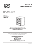
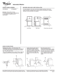
1
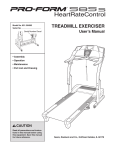
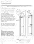
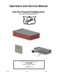
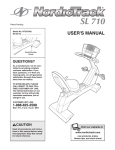
Service Manual
KT
COUNTER
Please read this manual completely before attempting to
install, operate or service this equipment
This document is prepared for trained Duke service technicians. It is not to be used by anyone not properly
qualified to perform these procedures.
This Service Manual is not all encompassing. If you have not been trained on servicing this product, be sure
to read the manual completely before attempting servicing. Be sure all necessary tools, test equipment, and
skills are available. Those procedures for which you do not have the proper skills and test equipment must be
performed only by a qualified Duke trained service technician.
This manual is Copyright © 2010 Duke Manufacturing Co. All rights reserved.
Reproduction without written permission is prohibited. Duke is a registered
trademark of the Duke Manufacturing Co.
Duke Manufacturing Co.
2305 N. Broadway
St. Louis, MO 63102
Phone: 314-231-1130
Toll Free: 1-800-735-3853
Fax: 314-231-5074
www.dukemfg.com
P/N 229050A
Service Manual for KT Counter
IMPORTANT WARNING AND SAFETY INFORMATION
THIS MANUAL HAS BEEN PREPARED FOR PERSONNEL QUALIFIED TO INSTALL
ELECTRICAL EQUIPMENT, WHO SHOULD PERFORM THE INITIAL FIELD STARTUP AND
ADJUSTMENTS OF THE EQUIPMENT COVERED BY THIS MANUAL.
READ THIS MANUAL THOROUGHLY BEFORE OPERATING, INSTALLING OR
PERFORMING MAINTENANCE ON THE EQUIPMENT.
Failure to follow all the instructions in
this manual can cause property damage, injury or death.
Improper installation, adjustment,
alteration, service or maintenance can cause property
damage, injury or death.
Electrical connections should be
performed only by a certified professional.
Electrical and grounding connections
must comply with the applicable portions of the National
Electric Code and/or all local electric codes. Failure to
comply with this procedure can cause property damage,
injury or death.
Before connecting the unit to the
electrical supply, verify that the electrical and grounding
connections comply with the applicable portions of the
National Electric Code and/or other local electrical codes.
Failure to comply with this procedure can cause property
damage, injury or death.
Before connecting the unit to the
electrical supply, verify that the electrical connection
agrees with the specifications on the data plate. Failure to
comply with this procedure can cause property damage,
injury or death.
UL73 grounding instructions: This
appliance must be connected to a grounded, metal,
permanent wiring system. Or an equipment-grounding
conductor must be run with the circuit conductors and
connected to the equipment-grounding terminal or lead
on the appliance. Failure to comply with this procedure
can cause property damage, injury or death.
Appliances equipped with a flexible electric
supply cord, are provided with a three-prong grounding
plug. It is imperative that this plug be connected into
2
a properly grounded three-prong receptacle. Failure to
comply with this procedure can cause property damage,
injury or death.
If the receptacle is not the proper
grounding type, contact an electrician. Do not remove
the grounding prong from the plug. Failure to comply
with this procedure can cause property damage, injury
or death.
Before performing any service that
involves electrical connection or disconnection and/or
exposure to electrical components, always perform the
Electrical LOCKOUT/TAGOUT Procedure. Disconnect
all circuits. Failure to comply with this procedure can
cause property damage, injury or death.
Before removing any sheet metal panels
or servicing this equipment, always perform the Electrical
LOCKOUT/TAGOUT Procedure. Be sure all circuits are
disconnected. Failure to comply with this procedure can
cause property damage, injury or death.
Do not operate this equipment without
properly placing and securing all covers and access
panels. Failure to comply with this procedure can cause
property damage, injury or death.
Do not use or store gasoline or other
flammable vapors or liquids in the vicinity of this or any
other appliance. Failure to comply can cause property
damage, injury or death.
In the event of a power failure, do not
attempt to operate this appliance. Failure to comply can
cause property damage, injury or death.
Service Manual for KT Counter
TABLE OF CONTENTS
INTRODUCTION.............................................................................................................................4
KT COUNTER SPECIFICATIONS..........................................................................................4
INSTALLATION.......................................................................................................................4
Location..............................................................................................................................4
Leveling..............................................................................................................................4
Electrical Connection.........................................................................................................4
PARTS REMOVAL AND REPLACEMENT PROCEDURES.........................................................5
ELECTRICAL LOCKOUT/TAGOUT PROCEDURE.............................................................5
HOT FOOD TABLE AND DRY CHANNEL WARMERS.......................................................5
Toggle Switches.................................................................................................................5
Display Control Panel........................................................................................................5
Relay Box...........................................................................................................................6
Dry Channel Power ON/OFF Toggle Switch.....................................................................6
Solid State Relay (SSR).....................................................................................................7
Transformer........................................................................................................................7
Channel Assembly..............................................................................................................7
TOP COLD PAN ASSEMBLY..................................................................................................8
Evaporator..........................................................................................................................8
Thermostat..........................................................................................................................8
Top Cold Pan Compressor Assembly.................................................................................9
REFRIGERATED BASE UNIT................................................................................................9
Evaporator Fan Assembly..................................................................................................9
RBC Thermostat...............................................................................................................10
RBC Refrigeration System...............................................................................................11
RBC Door Gaskets...........................................................................................................11
RBC Door Adjustment.....................................................................................................11
LOAD CENTER......................................................................................................................11
Circuit Breaker Replacement...........................................................................................12
RECHARGING REFRIGERATION SYSTEM......................................................................12
Tools.................................................................................................................................12
Duke Service Bulletin Number 26 – Refrigeration System Evacuation..........................12
Duke Service Bulletin Number 35 – Accessing Sealed Refrigeration Systems...............13
SERVICE INFORMATION.............................................................................................................14
MAINTENANCE....................................................................................................................14
Stainless Steel Care and Cleaning....................................................................................14
Cleaning......................................................................................................................14
Preserving & Restoring...............................................................................................14
Heat Tint......................................................................................................................14
Compressor Air Filter Care..............................................................................................14
TROUBLESHOOTING GUIDE.....................................................................................................16
SCHEMATICS.................................................................................................................................18
3
Service Manual for KT Counter
INTRODUCTION
KT COUNTER SPECIFICATIONS
MODEL
VOLTAGE
KFC-KT 208
AMPERAGE WATTAGE
PHASE
15.4
3200
1
INSTALLATION
Location
The KT Counter is intended for indoor use only. Be sure
the chosen location has a floor strong enough to support
the total weight of the unit fully assembled and loaded with
food product. Reinforce the floor, if necessary, to provide
for maximum loading. For the most efficient operation, be
sure to provide good air circulation.
Leveling
The unit must be leveled during the installation process. Refer
to the KT Counter Operation and Installation Instructions
(Duke part number: 229350).
If additional leveling is required, each module of the unit is
equipped with adjustable feet. Always use a level to adjust
the KT Counter.
4
Use the leg adjustments to ensure that the unit is solid to
the floor surface at all contact points. Ensure that the unit
does not “rock” when pressure is applied to the top corners.
Electrical Connection
The KT Counter requires 208VAC, 3 Phase, 50/60 Hz.
Direct wiring KT Counter to the power supply must be
performed by a certified electrician and must comply with
local electrical codes.
REFER TO THE AMPERAGE
DATA LIST IN THE SPECIFICATIONS OR THE
SERIAL TAG DATA AND YOUR LOCAL CODE
OR THE NATIONAL ELECTRICAL CODE TO BE
SURE UNIT IS CONNECTED TO THE PROPER
POWER SOURCE. A PROTECTED CIRCUIT OF
THE CORRECT VOLTAGE AND AMPERAGE MUST
BE RUN FOR CONNECTION OF THE SUPPLY
CORD OR PERMANENT CONNECTION TO THE
UNIT. THE POWER MUST BE TURNED OFF
AND DISCONNECTED WHENEVER PERFORMING
MAINTENANCE OR REPAIR FUNCTIONS.
Service Manual for KT Counter
PARTS REMOVAL AND REPLACEMENT PROCEDURES
ELECTRICAL LOCKOUT/TAGOUT
PROCEDURE
4. Pull the switch forward out of the box enough to access
the electrical connections, being careful not to place
stress on the wires.
Before performing any service
that involves electrical connection or disconnection
and/or exposure to electrical components, always
follow the Electrical LOCKOUT/TAGOUT Procedure.
Disconnect all circuits. Failure to comply can cause
property damage, injury or death.
5. Loosen the screws securing the wires to the faulty switch,
remove the wires, and discard the switch.
The Electrical LOCKOUT/TAGOUT Procedure is used to
protect personnel working on an electrical appliance. Before
performing any maintenance or service that requires exposure
to electrical components, follow these steps:
1. In KT Load Center, place appliance to be replaced or
repaired circuit breaker in the OFF position.
6. Attach the wires to the replacement switch.
7. Install the new switch and reattach the switch plate.
8. Place the unit back in service and check it for proper
operation.
Display Control Panel
The KT Counter is equipped with two dry channel units,
installed in the Hot Food Table. Each dry channel unit has
its own Display Control Panel.
2. Place a lock or other device on Load Center door to
prevent someone from placing circuit breaker ON.
3. Place a tag on the Load Center door to indicate that
appliance has been disconnected for service and
power should not be restored until tag is removed by
maintenance personnel.
HOT FOOD TABLE AND DRY CHANNEL
WARMERS
Toggle Switches
There are two Toggle Switches mounted on the Hot Food
Table. These switches control the APW griddle and the
Hot Food
Toggle
Load
Hatco Taco
tower.
Display
Switches
Center
Figure 2: Dry Channel Display & Control Panel
1. Follow proper LOCKOUT/TAGOUT procedures
2. Remove the four screws securing the Display Control
Panel and carefully pull Display Control Panel away
from mounting surface.
3. If the Display Control Panel is to be completely removed,
label and disconnect wires.
4. Remove Display Control Panel.
Figure 1: Location of Toggle Switches
1. Follow proper LOCKOUT/TAGOUT procedures.
2. Remove the switch plate.
3. Remove the screws securing the failed switch.
5. Reverse procedure to install Display Control Panel.
Relay Box
Each Dry Channel unit is equipped with its own Relay Box.
The Relay Box is located under each unit. Each Relay Box
has an ON/OFF switch.
5
Service Manual for KT Counter
3. If complete Relay Box is to be replaced, label and
disconnect wires.
4. Remove the Relay Box.
5. If components in the Relay Box are to be removed,
remove the Relay Box cover.
6. Reverse procedure to assemble and install Relay
Box.
The following component removal is based
on the cover having been already removed.
Dry Channel Power ON/OFF Toggle Switch
1. Tag and disconnect the Relay Box ON/OFF Switch
wires.
Figure 3: Relay Box
1. Follow proper LOCKOUT/TAGOUT procedures.
2. Remove the four screws securing the Relay Box to the
bottom of the Dry Channel Unit.
2. Slide the Relay Box ON/OFF Switch out through front
of switch mount.
3. Reverse procedure to install a new Main Power ON/
OFF Switch.
Note: Location of Serial Data Plate,
Serial Number data plates
11/2007 and later.
Figure 4: Exploded View of Relay Box Internal Components
6
Service Manual for KT Counter
Solid State Relay (SSR)
Channel Assembly
The Heat Elements, Temperature Probes and RTDs are
embedded in a foil wrap that is attached to the bottom of
each Channel Assembly. These parts are not serviced in the
field. The entire Channel Assembly must be replaced in the
event of a failure of any of these parts.
1. Follow proper LOCKOUT/TAGOUT procedures.
2. Remove six screws (three on each side) attaching the
channel top frame to the tub.
3. Carefully lift the Channel Assembly out, taking care
not to damage wire connections.
Figure 5: Solid State Relays (SSR)
1. Tag and disconnect wires from the SSR to be replaced.
2. Remove the two screws attaching the SSR and remove
the SSR.
3. Reverse procedure to install a new SSR.
Transformer
Figure 7: Dry Channel Tub Assembly
4. Label and disconnect the wires from the foil wrap on
the Channel Assembly to the Control Board.
5. Using an ohmmeter test the resistance across the
entire heating element. It should read approximately
248Ω. Also test the RTD circuit, its normal reading is
approximately 1,000Ω. Replace the channel assembly
if either the heater circuit or RTD circuit are reading
out of tolerance.
6. Reverse this procedure to install the new Dry Channel
Assembly.
7. Return the Dry Channel unit to service and check for
proper operation.
Figure 6: 240/208 Step Down Transformer
1. Tag and disconnect the wires from the Transformer.
2. Remove four nuts attaching the transformer and remove
the Transformer.
3. Reverse procedure to install a new Transformer.
7
Service Manual for KT Counter
TOP COLD PAN ASSEMBLY
Top Cold Pan
Unit
Thermostat
Taco
Rails
Cold Pan
ON/OFF
Switch
Cold Pan
Digital
Thermostat
Figure 8: Cold Pan Unit
The KT Counter is equipped with two Cold Pans. Both
Cold Pans are mounted above the refrigerator unit and
angled toward the operator on each side. Refer to Duke
Manufacturing Service Bulletin Number 26 and the
Recharging Refrigeration System section of this manual
before completing Evaporator replacement procedures.
Figure 9: Location of Cold Pan Thermostat
The Top Cold Pan Thermostat is located in the compressor
compartment behind the louvered vent. The Top Cold Pan
Compressor is located next to the refrigerator doors on the
side of the KT Counter that does NOT have the refrigerator
temperature display.
1. Place the Main Power ON/OFF switch in the OFF
position.
Evaporator
2. Perform proper Lockout/Tagout procedures.
The evaporator coils embedded in the body of each Cold
Pan are not serviceable. Replace the entire Top Cold Pan
Assembly if an evaporator leak or failure occurs.
3. Remove the louvered vent.
1. Place the Main Power ON/OFF switch in the OFF
position.
2. Perform proper Lockout/Tagout procedures.
3. Evacuate coolant following procedures in the
RECHARGING REFRIGERATION SYSTEM
section of this manual.
4. Tag and disconnect thermostat wiring.
5. Disconnect the capillary tube.
6. Remove thermostat from mounting bracket.
7. Install new thermostat being careful not to kink capillary
tube while reconnecting it.
8. Referring to tags, reconnect wires.
9. Set the thermostat according to Subway® guidelines
4. Disconnect the coolant tubing.
10. Reattach front panel and air filters.
5. Lift Top Cold Pan Assembly out of the KT Counter.
11. Restore power to the KT Counter.
6. Install new Top Cold Pan Assembly.
12. Allow the Top Cold Pan to cool for approximately twenty
minutes before performing a temperature check on each
channel.
7. Braze coolant lines from new Top Cold Pan to compressor
lines.
8. Charge the cooling system. Refer to the RECHARGING
REFRIGERATION SYSTEM section of this manual.
8
13. Adjust Thermostat as needed.
Service Manual for KT Counter
Top Cold Pan Compressor Assembly
REFRIGERATED BASE UNIT
Compressor
Compartment
Refrigerated
Base
RBC
Temperature Display
Figure 10: Compressor Assembly
The Top Pan Compressor Assembly is located behind the
louvered vent next to the refrigerator. It is on the side of the
KT Counter that does NOT have the refrigerator temperature
display.
1. Place the Main Power ON/OFF switch in the OFF
position.
Figure 11: Refrigerator Unit with Temperature
Display
The refrigerator unit is located below the Top Cold Pan Unit.
The refrigerator can be accessed from both sides of the KT
Counter. The side with the temperature display is considered
to be the front of the refrigerator unit. The refrigerator’s
compressor is located behind the louvered vent to the left
of the left front door.
2. Perform proper Lockout/Tagout procedures.
Evaporator Fan Assembly
3. Remove the louvered vent.
The Evaporator Fan Assembly is accessed through the
louvered panel on the inside of the RBC. The assembly is
equipped with two fans.
4. Remove the air filter.
5. Remove side panel.
6. Tag and disconnect compressor wiring.
7. Disconnect coolant tubing from evaporator unit. Refer to
the RECHARGING REFRIGERATION SYSTEM section
of the manual for proper evacuation procedures.
8. Remove mounting bolts.
9. Slide compressor unit out through the front of the unit.
1. Place the Main Power ON/OFF switch in the OFF
position.
2. Perform proper Lockout/Tagout procedures.
3. Open the RBC doors and remove the shelf for easier
access to the louvered panel.
4. Remove the louvered on the inside wall of the RBC to
gain access to the Evaporator Fan Assembly.
10. Install new compressor assembly.
11. Reattach, braze, coolant lines.
12. Reconnect compressor wiring.
13. Reconnect wiring.
14. Charge the cooling system. Refer to the RECHARGING
REFRIGERATION SYSTEM section of this manual for
proper charging procedures.
15. Attach air filter and all panels.
16. Restore KT Counter to service and check for proper
compressor operation.
9
Service Manual for KT Counter
RBC Thermostat
RBC Thermostat
Figure 14: Location of the
Refrigerator Thermostat
Figure 12: Evaporator Fan assembly
5. Remove the thumbscrews securing the Evaporator Fan
Assembly to the Evaporator Assembly.
6. Carefully lift the Evaporator Fan Assembly out of the
Evaporator Assembly. Be careful not to pull to hard on
the fan wiring.
The RBC Thermostat is located in the compressor
compartment behind the louvered vent.
1. Place Main Power ON/OFF switch in the OFF position.
2. Perform proper Lockout/Tagout procedures.
3. Open the louvered vent.
4. Tag and disconnect RBC Thermostat wiring.
5. Disconnect the capillary tube; be careful not to kink the
tube.
6. Remove RBC Thermostat from mounting bracket.
7. Reverse these procedures to install a new RBC
Thermostat.
8. Set the new thermostat according to Subway® standards.
9. Restore power to the KT Counter; monitor the RBC for
proper operation.
10. Readjust the thermostat setting as needed.
Figure 13: Evaporator Fans
7. Tag and disconnect the Evaporator Fan wires.
8. A separate bracket secures each fan; remove the 2 nuts
securing the faulty fan.
9. Reverse this procedure to install a new Evaporator
Fan
10
Service Manual for KT Counter
RBC Refrigeration System
The RBC unit is a 4 door model with access from both sides
of the KT Counter. Two of doors, one on each side are larger.
For the larger door use 19 inch gasket part number, 216636.
The smaller doors use a 17 inch gasket, part number, 216645.
Center
Shelf
1. Pull gasket out of door panel groove.
2. Press new gasket in groove.
3. Ensure door seals properly. To test for proper seal use a
sheet of paper approximately the size of dollar bill. Close
the door on the piece of paper; it should pull snugly.
4. Adjust door as necessary.
Side
Louvered Panel
Refrigeration
Unit
Figure 15: RBC Refrigeration System
1. Place Main Power ON/OFF switch in OFF position.
2. Perform proper Lockout/Tagout procedures.
3. Evacuate coolant following procedures in the
RECHARGING REFRIGERATION SYSTEM section
of this manual.
4. Remove center shelf for easier access.
5. Remove the side louvered panel.
6. Tag and disconnect wiring.
7. Remove Refrigeration Unit mounting hardware.
8. Remove the screws holding the evaporator assembly to
the RBC cabinet.
RBC Door Adjustment
Over time and with repeated use the RBC doors may begin
to sag. When this occurs, door adjustment is required.
1. Open the sagging door to its full open position.
2. Check the hinges for tightness. If they are loose, snug
them up but don’t over tighten them.
3. Place a flat-headed screwdriver against the inside edge
of the top hinge, tap it with a small hammer, using light
taps until the door is lined up.
4. Repeat for the bottom hinge if needed.
5. Tighten all of the hinge screws.
LOAD CENTER
Load Center
9. Reverse procedure to install new Refrigeration Unit.
RBC Door Gaskets
Figure 17: Location of KT Counter Load Center
The Load Center is located behind the cabinet door on the
end of the unit nearest the Dry Channel Warmer.
Figure 16: Refrigerator Door Gasket
11
Service Manual for KT Counter
Circuit Breaker Replacement
RECHARGING REFRIGERATION SYSTEM
Tools
Standard hand and refrigeration tools
Refrigerant Type: R-134A or R0404A. Refer to the unit’s
specification tag for the correct refrigerant type.
Always have the serial number of the refrigeration
unit whenever ordering refrigeration parts.
Duke Service Bulletin Number 26 – Refrigeration
System Evacuation
Circuit
Breakers
Figure 18: Location of Circuit Breakers
1. Place the Main Power ON/OFF switch in the OFF
position.
Prior to refrigeration system service, special
care must be taken during the evacuation process to remove
air, moisture and other non-condensable gasses from the
system. Duke Manufacturing recommends the following
triple evacuation method. Failure to follow this procedure
may result in poor refrigeration system performance.
1. Evacuate system to 1500 microns.
2. Perform proper Lockout/Tagout procedures.
2. Break vacuum to 2 psig with dry nitrogen. If dry nitrogen
is unavailable, use same type of refrigerant as used in
system.
3. Tag and disconnect the affected circuit breaker wires.
3. Evacuate system to 1500 microns.
4. Pull the circuit breaker out of its mounting slots.
4. Break vacuum to 2 psig with dry nitrogen. If dry nitrogen
is unavailable, use same type of refrigerant as used in
system.
5. Push the new circuit breaker into the slot; ensure that
it locks into position.
6. Refer to the tags, and reconnect the wires.
7. Restore the KT Counter to service and check the circuit
breaker for proper operation.
Refer to Troubleshooting section if replacement
breaker does not solve problem.
12
5. Evacuate system to 500 microns. The system is now ready
to receive refrigerant charge according to information
on data plate.
NEVER USE OXYGEN OR
ACETYLENE IN PLACE OF REFREGERANT
AND DRY NITROGEN FOR LEAK TESTING. A
VIOLENT EXPLOSION MAY RESULT, CAUSING
PERSONAL INJURY OR DEATH. ALWAYS USE
A PRESSURE REGULATOR WHEN USING
NITROGEN TO PRESSURE TEST, FAILURE
TO DO SO WILL RESULT IN EXTREMELY
HIGH PRESSURE, WHICH COLD EXCEED THE
BURST PRESSURE OF THE COMPRESSOR OR
OTHER SYSTEM COMPONENTS AND RESULT
IN PERSONAL INJURY OR DEATH.
Service Manual for KT Counter
Duke Service Bulletin Number 35 – Accessing
Sealed Refrigeration Systems
To analyze the performance of a refrigeration system,
record temperature readings. Convert temperature
into pressure using a standard pressure/temperature
chart. When it is necessary to service a factory sealed
refrigeration system and return it to its properly sealed
condition, strictly adhere to the following approved
procedure.
NOTE: Ensure that there is enough process hose
(approximately 12") available to complete the repair. If not,
install a new process hose before repair sequence.
1. Install a temporary access valve on the high and low side
of process hoses as close to factory crimps as possible.
4. After completing proper evacuation method,
recharge system, using proper refrigerant
according to information on the data plate.
Refrigerated Base Unit: 8 oz of R-134a refrigerant
Tri-Channel Cold Pan Unit: 16 oz of R404a refrigerant
5. Continue crimping process hose just below temporary
valve and again 2" below crimp.
6. With crimp tool in place, remove temporary valve.
7. Braze shut end of process hose.
8. Allow to cool for about 5 minutes.
9. Remove crimp tool.
10. Check brazed end for leaks.
2. Use temporary valves to perform repair.
Note: Duke Manufacturing will not reimburse the cost
of permanently installed valves.
3. After completing repair, evacuate system using the triple
evacuation method.
13
Service Manual for KT Counter
SERVICE INFORMATION
MAINTENANCE
Heat Tint
Stainless Steel Care and Cleaning
Darkened areas, called heat tint, may appear on stainless steel
exposed to excessive heat, which causes the protective film to
thicken. It is unsightly but is not a sign of permanent damage.
Cleaning
Stainless steel contains 70-80% iron, which will rust if not
properly maintained. It also contains 12-30% chromium,
which forms an invisible passive, protective film that shields
against corrosion. If the film remains intact, the stainless
steel will remain intact. However, if the film is damaged, the
stainless steel can break down and rust. To prevent stainless
steel breakdown, follow these steps:
CAUTION: Never use any metal tools. Scrapers, files,
wire brushes or scouring pads (except for
stainless steel scouring pads) will mar the
surface.
CAUTION: Never use steel wool, which will leave
behind particles that rust.
CAUTION: Never use acid-based or chloride-containing
cleaning solutions, which will break down
the protective film.
CAUTION: Never rub in a circular motion.
CAUTION: Never leave any food products or salt on the
surface. Many foods are acidic. Salt contains
chloride.
For routine cleaning, use warm water, mild soap or detergent
and a sponge or soft cloth.
For heavy-duty cleaning, use warm water, a degreaser and
a plastic, stainless steel or Scotch-Brite pad.
Always rinse thoroughly. Always rub gently in the direction
of the steel grain.
Preserving & Restoring
Special stainless steel polishing cleaners can preserve and
restore the protective film.
Preserve the life of stainless steel with a regular application
of a high quality stainless steel polishing cleaner as a final
step to daily cleaning.
If signs of breakdown appear, restore the stainless steel
surface. First, thoroughly clean, rinse and dry the surface.
Then, on a daily basis, apply a high-quality stainless steel
polish according to manufacturer’s instructions.
14
To remove heat tint, follow the routine cleaning procedure.
Stubborn heat tint will require heavy-duty cleaning.
To reduce heat tint, limit the exposure of equipment to
excessive heat.
Compressor Air Filter Care
Louvered Panel
Air Filters
Figure 19: Location of
Compressor Air Filters
The Compressor Air Filters are located behind the large
louvered vent mounted on the front and rear of the unit.
Clean the air filters with mild soap and water once a month.
Service Manual for KT Counter
1. Lift the louvered vent panel up and away from the front
of the unit.
2. Gently pull the filters out of their mountings.
CAUTION:Do not use a high-pressure hose to rinse
the filters. The high-pressure water will
damage the filter mesh.
5. Allow the filters to dry thoroughly before reinstalling
them.
6. Install the filter and reattach the louvered vent.
7. If replacement filters are required refer to the parts
list for the correct part number.
Figure 20: Air Filter Cleaning
3. Wash the filters in a mild soap and warm water solution.
4. Rinse with warm water.
15
Service Manual for KT Counter
TROUBLESHOOTING GUIDE
SYMPTOM
POSSIBLE CAUSE
REMEDY
KT Counter does not operate.
No Power
Make sure Main Power switch is in the ON
position.
Check Main Circuit Breaker
KT Counter has power but
Tortilla Griddle does not heat.
No Power
Make sure Tortilla Griddle Power Switch is in
the ON position.
Check Tortilla Griddle Circuit Breaker in Load
Center
Bad Power Switch
Replace Tortilla Griddle Power Switch.
Open Tortilla Griddle Heat
Element
Replace Tortilla Griddle Heat Element.
No Power
Make sure Dry Channel Power Switch is in ON
position
Check Dry Channel Display Control Panel
setting; should be 275°F.
Check Dry Channel Circuit Breakers.
Bad Power Switch
Replace Power Switch.
Display Control Panel Malfunction
Replace the Display Control Panel.
Relay Box failure
Replace the Relay Box.
Dry Channel unit is working but
one channel does not heat.
Open in Heat Element circuit.
Replace channel assembly.
KT Counter unit has power but
Taco Tower doesn’t heat or light.
No Power
Make sure Taco Tower Power Switch is in ON
position.
Check Taco Tower Circuit Breaker.
Taco Tower lights come on but it
doesn’t heat.
Failed Infrared Heater
Replace Infrared Heater.
KT Counter unit has power but
Tri-Channel unit doesn’t get
cold.
No Power
Make sure Tri-Channel Unit Power Switch is in
ON position.
Check Tri-Channel Unit Circuit Breaker.Check
Thermostat setting.
KT Counter unit has power but
Dry Channel Unit will not heat.
16
Service Manual for KT Counter
TROUBLESHOOTING GUIDE (CONTINUED)
SYMPTOM
POSSIBLE CAUSE
REMEDY
Cold Pan Unit doesn’t get cold.
Coolant Leak
Repair Leak referring to Duke Service Bulletin
Number 26.
Replace Cold Pan.
Replace Compressor Assembly.
Defective Thermostat
Replace Cold Pan Thermostat.
Dirty Compressor Air Filter
Clean or replace Air Filter.
Failed Condenser Cooling Fan
Replace Condenser Cooling Fan.
Condenser Motor Failure
Replace Condenser Assembly.
No Power
Check Refrigerator Unit Circuit Breaker.
Thermostat Setting
Check Thermostat Setting.
Defective Thermostat
Replace Thermostat.
Dirty Compressor Air Filter
Clean or replace Air Filter.
Failed Condenser Cooling Fan
Replace Condenser Cooling Fan.
Coolant Leak
Repair Leak referring to Duke Service Bulletin
Number 26.
Replace Compressor unit if needed.
Replace Evaporator unit if needed.
Evaporator Fan Failure
Replace Evaporator Fan Assembly.
Door Gaskets Leaking Excessively
Replace Door Gaskets.
KT Counter has power but
Refrigerator does not get cold.
17
Service Manual for KT Counter
SCHEMATICS
Figure 21. Wiring Diagram Side A
18
Service Manual for KT Counter
Figure 22. Wiring Diagram Side B
19
Service Manual for KT Counter
Duke Manufacturing Co.
2305 N. Broadway
St. Louis, MO 63102
Phone: 314-231-1130
Toll Free: 1-800-735-3853
Fax: 314-231-5074
www.dukemfg.com
20
P/N 229050