1
MAINTENANCE INTERVALS
Operation and Maintenance
Manual Excerpt
© 2010 Caterpillar
All Rights Reserved
®
®
SEBU7147-05
October 2009
Operation and
Maintenance
Manual
3508, 3512 and 3516 Generator Sets
5PW1-Up (Generator Set)
6WW1-Up (Generator Set)
8TW1-Up (Generator Set)
SAFETY.CAT.COM
86
Maintenance Section
Maintenance Interval Schedule
SEBU7147-05
i03736635
Maintenance Interval Schedule
SMCS Code: 1000; 4450; 7500
Ensure that all safety information, warnings and
instructions are read and understood before any
operation or any maintenance procedures are
performed.
An authorized operator may perform the maintenance
items with daily intervals. An authorized operator may
perform the maintenance items with intervals of every
week. The maintenance that is recommended for all
other maintenance intervals must be performed by an
authorized service technician or by your Caterpillar
dealer.
The user is responsible for the performance of all
maintenance which includes the following items:
performing all adjustments, using proper lubricants,
fluids, and filters, and replacing old components with
new components due to normal wear and aging .
Failure to adhere to proper maintenance intervals and
procedures may result in diminished performance of
the product and/or accelerated wear of components.
Before each consecutive interval is performed, all
maintenance from the previous intervals must be
performed.
Choose the interval that occurs first in order to
determine the correct maintenance interval: fuel
consumption, service hours, and calendar time .
Products that operate in severe operating conditions
may require more frequent maintenance.
All of the following will affect the oil change interval:
operating conditions, fuel type, oil type, and size of
the oil sump . Scheduled oil sampling analyzes used
oil in order to determine if the oil change interval is
suitable for your specific engine.
In the absence of scheduled oil sampling, replace
the engine oil and filters according to the following
intervals:
If the engine has a shallow oil sump, change the oil
after every 250 service hours.
If the engine has a standard oil sump, change the oil
after every 500 service hours.
If the engine has a deep oil sump, change the oil
after every 1000 service hours.
Refer to this Operation and Maintenance Manual,
“Engine Oil and Filter - Change” in order to determine
the oil change interval that is suitable for your specific
engine.
To determine the maintenance intervals for the
overhauls, refer to this Operation and Maintenance
Manual, “Maintenance Recommendations” .
Unless other instructions are provided, perform
maintenance and perform repairs under the following
conditions:
The starting system is disabled.
The engine is stopped.
The generator does not pose an electrical shock
hazard.
The generator is disconnected from the load.
When Required
Battery - Recycle .................................................. 88
Batteries - Replace ............................................... 88
Battery or Battery Cable - Disconnect .................. 90
Engine Air Cleaner Element (Dual Element) Clean/Replace .................................................. 101
Engine Air Cleaner Element (Single Element) Clean/Replace .................................................. 103
Fuel System - Prime ............................................ 114
Generator Bearing - Lubricate ............................ 120
Generator Set - Test ........................................... 125
Generator Set Alignment - Check ....................... 126
Generator Winding - Test .................................... 128
Maintenance Recommendations ........................ 133
Rotating Rectifier - Check ................................... 141
Varistor - Test ...................................................... 145
Daily
Control Panel - Inspect/Test .................................. 91
Cooling System Coolant Level - Check ................ 96
Engine Air Cleaner Service Indicator - Inspect ... 106
Engine Air Precleaner - Clean ............................ 107
Engine Oil Level - Check .................................... 108
Fuel Tank Water and Sediment - Drain ................ 116
Generator Bearing Temperature - Test/Record ... 124
Generator Load - Check ..................................... 124
Walk-Around Inspection ...................................... 146
Every Week
Automatic Start/Stop - Inspect .............................. 88
Battery Charger - Check ....................................... 89
Electrical Connections - Check ........................... 100
Generator - Inspect .............................................. 118
Generator Lead - Check ..................................... 124
Space Heater - Test ............................................ 142
Stator Winding Temperature - Test ..................... 144
Voltage and Frequency - Check ......................... 146
Initial 250 Service Hours
Engine Speed/Timing Sensor - Clean/Inspect ..... 112
Engine Valve Lash - Inspect/Adjust ..................... 113
SEBU7147-05
87
Maintenance Section
Maintenance Interval Schedule
Speed Sensor - Clean/Inspect ............................ 142
Every 6000 Service Hours or 6 Years
Every 250 Service Hours
Alternator - Inspect ............................................... 88
Cooling System Coolant (ELC) - Change ............. 94
Cooling System Water Temperature Regulator Replace ............................................................... 99
Engine Speed/Timing Sensor - Clean/Inspect ..... 112
Speed Sensor - Clean/Inspect ............................ 142
Starting Motor - Inspect ...................................... 144
Water Pump - Inspect ......................................... 147
Battery Electrolyte Level - Check .......................... 89
Belts - Inspect/Adjust/Replace .............................. 90
Cooling System Supplemental Coolant Additive
(SCA) - Test/Add ................................................. 97
Engine Oil Sample - Obtain ................................ 109
Fan Drive Bearing - Lubricate .............................. 113
Hoses and Clamps - Inspect/Replace ................ 132
Radiator - Clean .................................................. 140
Initial 500 Hours (for New Systems, Refilled
Systems, and Converted Systems)
Between 7500 and 9000 Service Hours
Overhaul (Top End) ............................................. 137
Between 15 000 and 18 000 Service Hours
Cooling System Coolant Sample (Level 2) Obtain ................................................................. 97
Overhaul (Top End) ............................................. 137
Every 500 Service Hours
Between 22 500 and 27 000 Service Hours
Cooling System Coolant Sample (Level 1) Obtain ................................................................. 96
Engine Oil and Filter - Change ............................ 110
Overhaul (Major) ................................................. 135
Every 1000 Service Hours
Engine - Clean .................................................... 100
Engine Crankcase Breather - Clean ................... 107
Engine Protective Devices - Check ..................... 112
Fuel Control Linkage - Check/Lubricate .............. 113
Fuel System Primary Filter - Clean/Inspect/
Replace .............................................................. 114
Fuel System Secondary Filter - Replace ............. 115
Generator Winding Insulation - Test ................... 129
Every 2000 Service Hours
Crankshaft Vibration Damper - Inspect ................. 99
Engine Mounts - Check ...................................... 108
Engine Valve Lash - Inspect/Adjust ..................... 113
Generator Set Vibration - Test/Record ................ 127
Turbocharger - Inspect ........................................ 144
Every 2000 Service Hours or 6 Months
Generator - Dry .................................................... 117
Stator Lead - Check ............................................ 144
Every Year
Cooling System Coolant Sample (Level 2) Obtain ................................................................. 97
Generator Bearing - Inspect ............................... 120
Every 3000 Service Hours or 2 Years
Cooling System Coolant (DEAC) - Change .......... 92
Every 3000 Service Hours or 3 Years
Cooling System Coolant Extender (ELC) - Add .... 95
Every 228 000 L (60 000 US gal) of Fuel or
6000 Service Hours or 6 Years
Standby Generator Set Maintenance
Recommendations ............................................ 143
Overhaul
Generator Bearing - Replace .............................. 123
Overhaul Considerations .................................... 138
88
Maintenance Section
Alternator - Inspect
SEBU7147-05
i02676048
• Recycling facility
Alternator - Inspect
i01041029
SMCS Code: 1405-040
Batteries - Replace
Caterpillar recommends a scheduled inspection
of the alternator. Inspect the alternator for loose
connections and proper battery charging. Inspect the
ammeter (if equipped) during engine operation in
order to ensure proper battery performance and/or
proper performance of the electrical system. Make
repairs, as required.
Check the alternator and the battery charger for
proper operation. If the batteries are properly
charged, the ammeter reading should be very near
zero. All batteries should be kept charged. The
batteries should be kept warm because temperature
affects the cranking power. If the battery is too cold,
the battery will not crank the engine. The battery will
not crank the engine, even if the engine is warm.
When the engine is not run for long periods of time
or if the engine is run for short periods, the batteries
may not fully charge. A battery with a low charge will
freeze more easily than a battery with a full charge.
SMCS Code: 1401-510
Batteries give off combustible gases which can
explode. A spark can cause the combustible gases to ignite. This can result in severe personal injury or death.
Ensure proper ventilation for batteries that are in
an enclosure. Follow the proper procedures in order to help prevent electrical arcs and/or sparks
near batteries. Do not smoke when batteries are
serviced.
1. Turn the key start switch to the OFF position.
Remove the key and all electrical loads.
2. Turn OFF the battery charger. Disconnect the
charger.
i01942284
Automatic Start/Stop - Inspect
SMCS Code: 4462
The generator set must be ready to operate under a
load at any time. After performing maintenance on
the generator set, inspect the position of the control
switches. Ensure the following conditions:
• The starting system is enabled.
• The control switches are in the correct position for
automatic starting.
that are associated with the generator are enabled.
i00993589
Battery - Recycle
SMCS Code: 1401-005; 1401-510; 1401-535;
1401-561; 1401
Always recycle a battery. Never discard a battery.
Always return used batteries to one of the following
locations:
• An authorized battery collection facility
4. The POSITIVE “+” cable connects the POSITIVE
“+” battery terminal to the starting motor.
Disconnect the cable from the POSITIVE “+”
battery terminal.
Note: Always recycle a battery. Never discard a
battery. Return used batteries to an appropriate
recycling facility.
5. Remove the used battery.
• The switchgear and the automatic transfer switches
• A battery supplier
3. The NEGATIVE “-” cable connects the NEGATIVE
“-” battery terminal to the ground plane. Disconnect
the cable from the NEGATIVE “-” battery terminal.
6. Install the new battery.
Note: Before connecting the cables, ensure that the
key start switch is OFF.
7. Connect the cable from the starting motor to the
POSITIVE “+” battery terminal.
8. Connect the cable from the ground plane to the
NEGATIVE “-” battery terminal.
SEBU7147-05
89
Maintenance Section
Battery Charger - Check
i01039758
Battery Charger - Check
SMCS Code: 1401-535
Checking Before Start-Up
Check the battery charger for proper operation. If
the batteries are properly charged, the needle of the
ammeter will register near “0” (zero).
The battery charger must not produce excessive
current during start-up. Alternatively, the charger
must be automatically disconnected for start-up.
If the engine has an alternator, the charger must
be automatically disconnected during start-up and
during engine operation.
Charging the Battery
Perform one of the following procedures if the battery
shows symptoms of overcharging:
• Reduce the rate of charging by a significant
amount. Complete the charging at the reduced
rate.
• Turn OFF the charger.
Table 25 describes the effects of overcharging on
different types of batteries.
Table 25
Effects of Overcharging Batteries
Type of Battery
Effect
Caterpillar General Service
Batteries
Caterpillar Premium High
Output Batteries
All of the battery cells have
a low level of electrolyte.
Never disconnect any charging unit circuit or battery circuit cable from the battery when the charging unit is operated. A spark can cause an explosion from the flammable vapor mixture of hydrogen and oxygen that is released from the electrolyte through the battery outlets. Injury to personnel can be the result.
Perform the following procedure to charge the
battery:
1. Ensure that the charger is turned OFF.
2. Adjust the voltage of the charger in order to match
the voltage of the battery.
3. Connect the POSITIVE “+” lead of the charger
to the POSITIVE “+” battery terminal. Connect
the NEGATIVE “-” lead of the charger to the
NEGATIVE “-” battery terminal.
When the plates of the
battery are inspected
through the filler holes, the
plates may appear to be
warped. This is caused by
an excessive temperature.
The battery may not pass
a load test.
Caterpillar Maintenance
Free Batteries
The battery may not accept
a charging current.
The battery may not pass
a load test.
Checking After Stopping
Ensure that the battery charger is connected
properly. Observe the meter of the charger. Record
the amperage.
4. Turn ON the battery charger.
Overcharging of Batteries
Overcharging reduces the service life of batteries.
Use a battery charger that will not overcharge the
battery. DO NOT charge the battery if the meter of
the battery charger is in the RED zone.
Overcharging is indicated by the following symptoms:
• The battery is very warm to the touch.
• A strong odor of acid is present.
• The battery emits smoke or a dense vapor (gas).
i02601752
Battery Electrolyte Level Check
SMCS Code: 1401-535-FLV
When the engine is not run for long periods of time or
when the engine is run for short periods, the batteries
may not fully recharge. Ensure a full charge in order
to help prevent the battery from freezing.
90
Maintenance Section
Battery or Battery Cable - Disconnect
SEBU7147-05
All lead-acid batteries contain sulfuric acid which
can burn the skin and clothing. Always wear a face
shield and protective clothing when working on or
near batteries.
1. Remove the filler caps. Maintain the electrolyte
level to the “FULL” mark on the battery.
If the addition of water is necessary, use distilled
water. If distilled water is not available use clean
water that is low in minerals. Do not use artificially
softened water.
2. Check the condition of the electrolyte with the
245-5829 Coolant Battery Tester Refractometer.
3. Keep the batteries clean.
Clean the battery case with one of the following
cleaning solutions:
• A mixture of 0.1 kg (0.2 lb) of baking soda and
1. Turn the start switch to the OFF position. Turn the
ignition switch (if equipped) to the OFF position
and remove the key and all electrical loads.
2. Disconnect the negative battery terminal at the
battery that goes to the start switch. Ensure that
the cable cannot contact the terminal. When four
12 volt batteries are involved, the negative side of
two batteries must be disconnected.
3. Tape the leads in order to help prevent accidental
starting.
4. Proceed with necessary system repairs. Reverse
the steps in order to reconnect all of the cables.
i02667833
Belts - Inspect/Adjust/Replace
SMCS Code: 1357-025; 1357-040; 1357-510
Inspection
• A mixture of 0.1 L (0.11 qt) of ammonia and 1 L
Inspect the alternator belt and the fan drive belts for
wear and for cracking. Replace the belts if the belts
are not in good condition.
Thoroughly rinse the battery case with clean water.
Check the belt tension according to the information in
the Service Manual, “Specifications”.
1 L (1 qt) of clean water
(1 qt) of clean water
Use a fine grade of sandpaper to clean the
terminals and the cable clamps. Clean the items
until the surfaces are bright or shiny. DO NOT
remove material excessively. Excessive removal
of material can cause the clamps to not fit properly.
Coat the clamps and the terminals with 5N-5561
Silicone Lubricant, petroleum jelly or MPGM.
i01492654
Battery or Battery Cable Disconnect
SMCS Code: 1401; 1402-029
The battery cables or the batteries should not be
removed with the battery cover in place. The battery cover should be removed before any servicing is attempted.
Removing the battery cables or the batteries with
the cover in place may cause a battery explosion
resulting in personal injury.
Slippage of loose belts can reduce the efficiency
of the driven components. Vibration of loose belts
can cause unnecessary wear on the following
components:
• Belts
• Pulleys
• Bearings
If the belts are too tight, unnecessary stress is placed
on the components. This reduces the service life of
the components.
SEBU7147-05
91
Maintenance Section
Control Panel - Inspect/Test
Adjusting the Alternator Belt
For the proper torque specifications, refer to the
Service Manual, “Specifications” module.
Replacement
For applications that require multiple drive belts,
replace the drive belts in matched sets. Replacing
one drive belt of a matched set will cause the new
drive belt to carry more load because the older drive
belts are stretched. The additional load on the new
drive belt could cause the new drive belt to fail.
i03736663
Control Panel - Inspect/Test
SMCS Code: 4490-040; 4490-081; 7451-040;
7451-081
Illustration 63
g01092641
Typical alternator
(1) Mounting bolt
(2) Adjusting nuts
(3) Mounting bolt
1. Remove the drive belt guard.
Inspect the condition of the panel. If a component is
damaged, ensure that the component is repaired or
that the component is replaced. If equipped, ensure
that the electronic displays are operating properly.
Inspect the wiring for good condition. Ensure that the
wiring connections are secure.
Electronic Modular Control Panel 3
(EMCP 3)
2. Loosen mounting bolt (1), adjusting nuts (2) and
mounting bolt (3).
3. Turn adjusting nuts (2) in order to increase or
decrease the drive belt tension.
4. Tighten adjusting nuts (2). Tighten mounting bolt
(3). Tighten mounting bolt (1). For the proper
torque, see the Service Manual, “Specifications”
module.
5. Reinstall the drive belt guard.
If new drive belts are installed, check the drive belt
tension again after 30 minutes of engine operation at
the rated rpm.
Illustration 64
g01184041
3. Move the pulley in order to adjust the belt tension.
The Lamp Test button is located on the top right side
of the electronic control module. Press and hold
the Lamp Test button in order to test all of the LED
lights and the display screen. The LED lights and the
display screen should remain on until the button is
released. If any of the components do not pass this
test, replace the faulty components before starting
the engine.
4. Tighten the adjusting nut to the proper torque.
Switch Panel
5. Tighten the mounting bolt to the proper torque.
The Panel Lights switch should turn on the panel
lights. Toggle the switch in order to ensure that the
panel lights are working.
Adjusting the Fan Drive Belt
1. Loosen the mounting bolt for the pulley.
2. Loosen the adjusting nut for the pulley.
92
Maintenance Section
Cooling System Coolant (DEAC) - Change
SEBU7147-05
Annunciator Panel
Illustration 66
g00750410
(1) Coolant drain
Note: If the engine has a jacket water heater, drain
the coolant from the heater.
3. Open the coolant drain. Allow the coolant to drain.
Illustration 65
g01101388
It is possible to test the LED indicators and the horn
when the data link is connected and when the data
link is not connected. The Lamp Test button is located
near the top of the annunciator panel. Test both the
horn and the indicators by pressing and holding the
Lamp Test button. Replace any faulty components
before starting the engine.
i02062150
Cooling System Coolant
(DEAC) - Change
SMCS Code: 1350-044
Clean the cooling system before the recommended
maintenance interval if the following conditions exist:
• The engine overheats frequently.
• The coolant is foaming.
• Oil or fuel has entered the cooling system and the
coolant is contaminated.
Drain the Cooling System
1. Stop the engine and allow the engine to cool.
Close the water inlet for the separate circuit
aftercooler (if equipped). Ensure that the engine
will not start when the cooling system is drained.
2. Loosen the radiator filler cap slowly in order to
relieve any pressure. Remove the radiator filler
cap.
NOTICE
Dispose of used engine coolant properly or recycle.
Various methods have been proposed to reclaim used
coolant for reuse in engine cooling systems. The full
distillation procedure is the only method acceptable by
Caterpillar to reclaim the used coolant.
For information regarding the disposal and the
recycling of used coolant, consult your Caterpillar
dealer or consult Caterpillar Dealer Service Tools:
Inside U.S.A.: 1-800-542-TOOL
Inside Illinois: 1-800-541-TOOL
Canada: 1-800-523-TOOL
EAME phone: ++41-22-849 40 56
EAME fax: ++41-22-849 49 29
Clean the Cooling System
NOTICE
Use of commercially available cooling system cleaners may cause damage to cooling system components. Use only cooling system cleaners that are approved for Caterpillar engines.
1. After the cooling system has been drained, flush
the cooling system with clean water in order to
remove any debris.
2. Close the cooling system drain. Clean the cooling
system drain plugs and install the cooling system
drain plugs.
SEBU7147-05
93
Maintenance Section
Cooling System Coolant (DEAC) - Change
NOTICE
Fill the cooling system no faster than 19 L (5 US gal)
per minute to avoid air locks.
3. Fill the cooling system with a mixture of clean
water and Caterpillar Fast Acting Cooling System
Cleaner. Add .5 L (1 pint) of cleaner per 3.8 to 7.6 L
(1 to 2 US gal) of the cooling system capacity.
Install the radiator filler cap.
3. Fill the cooling system with a mixture of clean
water and Caterpillar Fast Acting Cooling System
Cleaner. Add .5 L (1 pint) of cleaner per 15 L
(4 US gal) of the cooling system capacity. Install
the radiator filler cap.
4. Open the water inlet for the separate circuit
aftercooler (if equipped). Start the engine. Operate
the engine for a minimum of 90 minutes with a
coolant temperature of at least 82 °C (180 °F).
4. Open the water inlet for the separate circuit
aftercooler (if equipped). Start the engine. Operate
the engine for a minimum of 30 minutes with a
coolant temperature of at least 82 °C (180 °F).
5. Stop the engine and allow the engine to cool.
Close the water inlet for the separate circuit
aftercooler (if equipped). Loosen the radiator
filler cap slowly in order to relieve any pressure.
Remove the radiator filler cap. Open the coolant
drain. Remove the cooling system drain plugs.
Allow the water to drain.
NOTICE
Improper or incomplete rinsing of the cooling system
can result in damage to copper and other metal components.
To avoid damage to the cooling system, make sure
to completely flush the cooling system with clear water. Continue to flush the system until all signs of the
cleaning agent are gone.
6. Flush the cooling system with clean water until
the water that drains is clean. Close the coolant
drain. Clean the cooling system drain plugs and
install the cooling system drain plugs. Open the
water inlet for the separate circuit aftercooler (if
equipped).
Cleaning a Cooling System that
has Heavy Deposits or Plugging
Note: For the following procedure to be effective,
there must be an active flow through the cooling
system components.
1. After the cooling system has been drained, flush
the cooling system with clean water in order to
remove any debris.
2. Close the coolant drain. Clean the cooling system
drain plugs and install the cooling system drain
plugs.
5. Stop the engine and allow the engine to cool.
Close the water inlet for the separate circuit
aftercooler (if equipped). Loosen the radiator
filler cap slowly in order to relieve any pressure.
Remove the radiator filler cap. Open the coolant
drain. Remove the cooling system drain plugs.
Allow the water to drain.
NOTICE
Improper or incomplete rinsing of the cooling system
can result in damage to copper and other metal components.
To avoid damage to the cooling system, make sure
to completely flush the cooling system with clear water. Continue to flush the system until all signs of the
cleaning agent are gone.
6. Flush the cooling system with clean water until
the water that drains is clean. Close the cooling
system drain. Clean the cooling system drain
plugs and install the cooling system drain plugs.
Fill the Cooling System
Note: For information about the proper coolant to
use, and for the capacity of the cooling system,
see this Operation and Maintenance Manual, “Refill
Capacities and Recommendations”.
NOTICE
Fill the cooling system no faster than 19 L (5 US gal)
per minute to avoid air locks.
1. Fill the cooling system with coolant/antifreeze.
After filling the cooling system, do not install the
radiator filler cap.
2. Open the water inlet for the separate circuit
aftercooler (if equipped). Start the engine. Operate
the engine in order to purge the air from the
cavities of the engine block. Allow the coolant to
warm and allow the coolant level to stabilize. Stop
the engine.
94
Maintenance Section
Cooling System Coolant (ELC) - Change
SEBU7147-05
3. Check the coolant level. Maintain the coolant to
the proper level on the sight gauge (if equipped).
If a sight gauge is not equipped, maintain the
coolant within 13 mm (.5 inch) below the bottom of
the filler pipe.
4. Clean the radiator filler cap. Inspect the gaskets of
the radiator filler cap. If the gaskets of the radiator
filler cap are damaged, discard the old radiator
filler cap and install a new radiator filler cap. If the
gaskets of the radiator filler cap are not damaged,
use a 9S-8140 Pressurizing Pump in order to
pressure test the radiator filler cap. The correct
pressure is stamped on the face of the radiator
filler cap. If the radiator filler cap does not maintain
the correct pressure, install a new radiator filler
cap.
5. Start the engine. Inspect the cooling system for
leaks and for proper operating temperature.
3. Open coolant drain (1).
NOTICE
Dispose of used engine coolant properly or recycle.
Various methods have been proposed to reclaim used
coolant for reuse in engine cooling systems. The full
distillation procedure is the only method acceptable by
Caterpillar to reclaim the used coolant.
For information regarding the disposal and the
recycling of used coolant, consult your Caterpillar
dealer or consult Caterpillar Dealer Service Tools:
Outside Illinois: 1-800-542-TOOL
Inside Illinois: 1-800-541-TOOL
Canada: 1-800-523-TOOL
EAME phone: ++41-22-849 40 56
EAME fax: ++41-22-849 49 29
Clean the Cooling System
i02062273
Cooling System Coolant (ELC)
- Change
1. After the cooling system has been drained, flush
the cooling system with clean water in order to
remove any debris.
2. Close the coolant drain.
SMCS Code: 1350-044-NL
Use only clean water to flush the cooling system
when Extended Life Coolant (ELC) is drained and
replaced.
NOTICE
Fill the cooling system no faster than 19 L (5 US gal)
per minute to avoid air locks.
Drain the Cooling System
3. Open the water inlet for the separate circuit
aftercooler (if equipped). Fill the cooling system
with clean water. Install the radiator filler cap.
Operate the engine until the temperature reaches
49 °C (120 °F) to 66 °C (150 °F).
1. Stop the engine and allow the engine to cool.
Close the water inlet for the separate circuit
aftercooler (if equipped). Ensure that the engine
will not start when the cooling system is drained.
2. Loosen the radiator filler cap slowly in order to
relieve any pressure. Remove the radiator filler
cap.
4. Stop the engine and allow the engine to cool.
Close the water inlet for the separate circuit
aftercooler (if equipped). Ensure that the engine
will not start when the cooling system is drained.
Loosen the radiator filler cap slowly in order to
relieve any pressure. Remove the radiator filler
cap.
5. Open the coolant drain. Allow the coolant to drain.
Flush the cooling system with clean water. Close
the coolant drain.
6. Repeat Steps 3, 4, and 5.
Fill the Cooling System
Illustration 67
(1) Coolant drain
g00736141
NOTICE
Fill the cooling system no faster than 19 L (5 US gal)
per minute to avoid air locks.
SEBU7147-05
95
Maintenance Section
Cooling System Coolant Extender (ELC) - Add
1. Fill the cooling system with Extended Life
Coolant (ELC). For the correct capacity of
the cooling system, see this Operation and
Maintenance Manual, “Refill Capacities and
Recommendations”. Do not install the radiator
filler cap.
2. Open the water inlet for the separate circuit
aftercooler (if equipped). Start the engine. Operate
the engine in order to purge the air from the
cavities of the engine block. Allow the ELC to
warm and allow the coolant level to stabilize. Stop
the engine.
3. Check the coolant level. Maintain the coolant to
the proper level on the sight gauge (if equipped).
If a sight gauge is not equipped, maintain the
coolant within 13 mm (.5 inch) below the bottom of
the filler pipe.
4. Clean the radiator filler cap. Inspect the gaskets of
the radiator cap. If the gaskets of the radiator filler
cap are damaged, discard the old radiator filler cap
and install a new radiator filler cap. If the gaskets
of the radiator filler cap are not damaged, use a
9S-8140 Pressurizing Pump in order to pressure
test the radiator filler cap. The correct pressure is
stamped on the face of the radiator filler cap. If the
radiator filler cap does not maintain the correct
pressure, install a new radiator filler cap.
5. Start the engine. Inspect the cooling system for
leaks and for proper operating temperature.
i02482066
Personal injury can result from hot coolant, steam
and alkali.
At operating temperature, engine coolant is hot
and under pressure. The radiator and all lines
to heaters or the engine contain hot coolant or
steam. Any contact can cause severe burns.
Remove cooling system pressure cap slowly to
relieve pressure only when engine is stopped and
cooling system pressure cap is cool enough to
touch with your bare hand.
Do not attempt to tighten hose connections when
the coolant is hot, the hose can come off causing
burns.
Cooling System Coolant Additive contains alkali.
Avoid contact with skin and eyes.
NOTICE
Care must be taken to ensure that fluids are contained
during performance of inspection, maintenance, testing, adjusting and repair of the product. Be prepared to
collect the fluid with suitable containers before opening any compartment or disassembling any component containing fluids.
Refer to Special Publication, NENG2500, “Caterpillar
Dealer Service Tool Catalog” for tools and supplies
suitable to collect and contain fluids on Caterpillar
products.
Cooling System Coolant
Extender (ELC) - Add
Dispose of all fluids according to local regulations and
mandates.
SMCS Code: 1352-544-NL
1. Loosen the cooling system filler cap slowly in
order to relieve pressure. Remove the cooling
system filler cap.
Cat ELC (Extended Life Coolant) does not require
the frequent additions of any supplemental cooling
additives which are associated with the present
conventional coolants. The Cat ELC Extender only
needs to be added once.
NOTICE
Use only Cat Extended Life Coolant (ELC) Extender
with Cat ELC.
Do NOT use conventional supplemental coolant additive (SCA) with Cat ELC. Mixing Cat ELC with conventional coolants and/or conventional SCA reduces the
Cat ELC service life.
Check the cooling system only when the engine is
stopped and cool.
2. It may be necessary to drain enough coolant from
the cooling system in order to add the Cat ELC
Extender.
3. Add Cat ELC Extender according to the
requirements for your engine's cooling system
capacity. Refer to the Operation and Maintenance
Manual, “Refill Capacities and Recommendations”
article for more information.
4. Clean the cooling system filler cap. Inspect the
gaskets on the cooling system filler cap. Replace
the cooling system filler cap if the gaskets are
damaged. Install the cooling system filler cap.
96
Maintenance Section
Cooling System Coolant Level - Check
SEBU7147-05
Cooling System Coolant Level
- Check
3. Clean the cooling system filler cap and check the
condition of the filler cap gaskets. Replace the
cooling system filler cap if the filler cap gaskets are
damaged. Reinstall the cooling system filler cap.
SMCS Code: 1350-535-FLV
4. Inspect the cooling system for leaks.
i01197583
Check the coolant level when the engine is stopped
and cool.
i02837191
Cooling System Coolant
Sample (Level 1) - Obtain
SMCS Code: 1350-008; 1395-008; 1395-554; 7542
Note: Obtaining a Coolant Sample (Level 1) is
optional if the cooling system is filled with Cat
ELC (Extended Life Coolant). Cooling systems that
are filled with Cat ELC should have a Coolant Sample
(Level 2) that is obtained at the recommended interval
that is stated in the Maintenance Interval Schedule.
Illustration 68
g00285520
Cooling system filler cap
Note: Obtain a Coolant Sample (Level 1) if the
cooling system is filled with any other coolant
instead of Cat ELC. This includes the following
types of coolants:
• Commercial long life coolants that meet the
Pressurized System: Hot coolant can cause serious burns. To open the cooling system filler cap,
stop the engine and wait until the cooling system
components are cool. Loosen the cooling system
pressure cap slowly in order to relieve the pressure.
Caterpillar Engine Coolant Specification -1
(Caterpillar EC-1)
• Cat DEAC (Diesel Engine Antifreeze/Coolant)
• Commercial heavy-duty coolant/antifreeze
Table 26
Recommended Interval
1. Remove the cooling system filler cap slowly in
order to relieve pressure.
2. Maintain the coolant level within 13 mm (0.5 inch)
of the bottom of the filler pipe. If the engine is
equipped with a sight glass, maintain the coolant
level to the proper level in the sight glass.
Type of Coolant
Level 1
Level 2
Cat DEAC
Every 250
Hours(1)
Yearly(1)(2)
Cat ELC
Optional(2)
Yearly(2)
(1)
This is the recommended interval for coolant samples for all
conventional heavy-duty coolant/antifreeze. This is also the
recommended interval for coolant samples of commercial
coolants that meet the Cat EC-1 specification for engine
coolant.
(2) The Level 2 Coolant Analysis should be performed sooner if a
problem is suspected or identified.
NOTICE
Always use a designated pump for oil sampling, and
use a separate designated pump for coolant sampling.
Using the same pump for both types of samples may
contaminate the samples that are being drawn. This
contaminate may cause a false analysis and an incorrect interpretation that could lead to concerns by both
dealers and customers.
Illustration 69
Typical filler cap gaskets
g00103639
Note: Level 1 results may indicate a need for
Level 2 Analysis.
SEBU7147-05
97
Maintenance Section
Cooling System Coolant Sample (Level 2) - Obtain
Obtain the sample of the coolant as close as possible
to the recommended sampling interval. In order
to receive the full effect of S·O·S analysis, you
must establish a consistent trend of data. In order
to establish a pertinent history of data, perform
consistent samplings that are evenly spaced.
Supplies for collecting samples can be obtained from
your Caterpillar dealer.
Submit the sample for Level 2 analysis.
Use the following guidelines for proper sampling of
the coolant:
Cooling System Supplemental
Coolant Additive (SCA) Test/Add
• Complete the information on the label for the
sampling bottle before you begin to take the
samples.
For additional information about coolant
analysis, see Special Publication, SEBU6251,
“Caterpillar Commercial Diesel Engines Fluids
Recommendations” or consult your Caterpillar dealer.
i02839449
SMCS Code: 1352-045; 1395-081
• Keep the unused sampling bottles stored in plastic
bags.
• Obtain coolant samples directly from the coolant
sample port. You should not obtain the samples
from any other location.
• Keep the lids on empty sampling bottles until you
are ready to collect the sample.
• Place the sample in the mailing tube immediately
after obtaining the sample in order to avoid
contamination.
• Never collect samples from expansion bottles.
• Never collect samples from the drain for a system.
Submit the sample for Level 1 analysis.
For additional information about coolant analysis,
see this Operation and Maintenance Manual, “Refill
Capacities and Recommendations” or consult your
Caterpillar dealer.
i01987714
Cooling System Coolant
Sample (Level 2) - Obtain
SMCS Code: 1350-008; 1395-008; 1395-554; 7542
Cooling system coolant additive contains alkali.
To help prevent personal injury, avoid contact with
the skin and eyes. Do not drink cooling system
coolant additive.
NOTICE
Excessive supplemental coolant additive concentration can form deposits on the higher temperature surfaces of the cooling system, reducing the engine's
heat transfer characteristics. Reduced heat transfer
could cause cracking of the cylinder head and other
high temperature components.
Excessive supplemental coolant additive concentration could also result in blockage of the heat exchanger, overheating, and/or accelerated wear of the water
pump seal.
Do not exceed the recommended amount of supplemental coolant additive concentration.
NOTICE
Care must be taken to ensure that fluids are contained
during performance of inspection, maintenance, testing, adjusting and repair of the product. Be prepared to
collect the fluid with suitable containers before opening any compartment or disassembling any component containing fluids.
NOTICE
Always use a designated pump for oil sampling, and
use a separate designated pump for coolant sampling.
Using the same pump for both types of samples may
contaminate the samples that are being drawn. This
contaminate may cause a false analysis and an incorrect interpretation that could lead to concerns by both
dealers and customers.
Refer to Special Publication, NENG2500, “Caterpillar
Dealer Service Tool Catalog” and to Special Publication, GECJ0003, “Cat Shop Supplies and Tools” for
tools and supplies suitable to collect and contain fluids on Caterpillar products.
Refer to Operation and Maintenance Manual,
“Cooling System Coolant Sample (Level 1) - Obtain”
for the guidelines for proper sampling of the coolant.
Note: Caterpillar recommends an S·O·S coolant
analysis (Level 1).
Dispose of all fluids according to applicable regulations and mandates.
98
Maintenance Section
Cooling System Supplemental Coolant Additive (SCA) - Test/Add
SEBU7147-05
Cooling Systems that Use
Conventional Coolant
Cooling Systems that Use Water
and SCA
This maintenance procedure is required for
conventional coolants such as DEAC.This
maintenance is NOT required for cooling systems
that are filled with Extended Life Coolant.
Test the Concentration of the SCA
Test the Concentration of the SCA
NOTICE
Do not exceed the recommended six percent supplemental coolant additive concentration.
Test the concentration of the SCA with the 8T-5296
Coolant Conditioner Test Kit.
Add the SCA, If Necessary
Pressurized System: Hot coolant can cause serious burns. To open the cooling system filler cap,
stop the engine and wait until the cooling system
components are cool. Loosen the cooling system
pressure cap slowly in order to relieve the pressure.
Test the concentration of the SCA with a 298-5311
Coolant Nitrite Test Kit for SCA or perform an S·O·S
Coolant Analysis. The test kit includes the following
items: a tool for the testing, 30 ampoules for testing
nitrite, instructions, and a case. 294-7420 Test
Kit contains the refill ampoules for the 298-5311
Coolant Nitrite Test Kit. Use the instructions that are
included with the test kit in order to properly conduct
the testing.
Refer to this Operation and Maintenance Manual,
“Maintenance Interval Schedule” for the times at
which the procedures should be conducted. Test the
concentration of the SCA more frequently if more
frequent testing is indicated by the results of the
S·O·S Coolant Analysis.
NOTICE
Do not exceed the recommended eight percent supplemental coolant additive concentration.
Add the SCA, If Necessary
1. Remove the cooling system filler cap slowly.
2. If necessary, drain some coolant in order to allow
space for the addition of the SCA.
3. Add the proper amount of SCA. For the
proper amount of SCA, refer to this Operation
and Maintenance Manual, “Refill Capacities
and Recommendations” topic. The proper
concentration of SCA depends on the type of
coolant that is used. For the proper concentration
of SCA, refer to Special Publication, SEBU6251,
“Caterpillar Commercial Diesel Engine Fluids
Recommendations”.
4. Clean the cooling system filler cap. Install the
cooling system filler cap.
Pressurized System: Hot coolant can cause serious burns. To open the cooling system filler cap,
stop the engine and wait until the cooling system
components are cool. Loosen the cooling system
pressure cap slowly in order to relieve the pressure.
1. Remove the cooling system filler cap slowly.
2. If necessary, drain some coolant in order to allow
space for the addition of the SCA.
3. Add the proper amount of SCA. For the proper
amount of SCA, refer to this Operation and
Maintenance Manual, “Refill Capacities and
Recommendations” topic. For the proper
concentration of SCA, refer to Special Publication,
SEBU6251, “Caterpillar Commercial Diesel
Engine Fluids Recommendations”.
4. Clean the cooling system filler cap. Install the
cooling system filler cap.
SEBU7147-05
99
Maintenance Section
Cooling System Water Temperature Regulator - Replace
i03645060
Cooling System Water
Temperature Regulator Replace
SMCS Code: 1355-510
Replace the water temperature regulator before
the water temperature regulator fails. This is a
recommended preventive maintenance practice.
Replacing the water temperature regulator reduces
the chances for unscheduled downtime. Refer to this
Operation and Maintenance Manual, “Maintenance
Interval Schedule” for the proper maintenance
interval.
A water temperature regulator that fails in a
partially opened position can cause overheating or
overcooling of the engine.
A water temperature regulator that fails in the closed
position can cause excessive overheating. Excessive
overheating could result in cracking of the cylinder
head or piston seizure problems.
A water temperature regulator that fails in the open
position will cause the engine operating temperature
to be too low during partial load operation. Low
engine operating temperatures during partial loads
could cause an excessive carbon buildup inside the
cylinders. This excessive carbon buildup could result
in an accelerated wear of the piston rings and wear
of the cylinder liner.
NOTICE
Failure to replace your water temperature regulator
on a regularly scheduled basis could cause severe
engine damage.
Caterpillar engines incorporate a shunt design cooling
system and require operating the engine with a water
temperature regulator installed.
If the water temperature regulator is installed incorrectly, the engine may overheat, causing cylinder head
damage. Ensure that the new water temperature regulator is installed in the original position. Ensure that
the water temperature regulator vent hole is open.
Do not use liquid gasket material on the gasket or
cylinder head surface.
Refer to two articles in the Disassembly and
Assembly Manual, “Water Temperature Regulators
- Remove and Water Temperature Regulators Install” for the replacement procedure of the water
temperature regulator, or consult your Caterpillar
dealer.
Note: If only the water temperature regulators are
replaced, drain the coolant from the cooling system to
a level that is below the water temperature regulator
housing.
i02871204
Crankshaft Vibration Damper
- Inspect
SMCS Code: 1205-040
The crankshaft vibration damper limits the torsional
vibration of the crankshaft. The visconic damper has
a weight that is located inside a fluid filled case.
Damage to the crankshaft vibration damper or failure
of the damper can increase torsional vibrations. This
can result in damage to the crankshaft and to other
engine components. A deteriorating damper can
cause excessive torsional vibrations.
A damper that is hot may be the result of excessive
torsional vibration, worn bearings, or damage to the
damper. Use an infrared thermometer to monitor the
temperature of the damper during operation. Follow
the instructions that are included with the infrared
thermometer. If the temperature reaches 100°C
(212 °F), consult your Caterpillar dealer.
Inspect the damper for evidence of dents, cracks,
and leaks of the fluid.
If a fluid leak is found, determine the type of fluid.
The fluid in the damper is silicone. Silicone has the
following characteristics: transparent, viscous, and
smooth.
If the fluid leak is oil, inspect the crankshaft seals for
leaks. If a leak is observed, replace all of the seals.
Inspect the damper and repair or replace the damper
for any of the following reasons.
• The damper is dented, cracked, or leaking.
• The paint on the damper is discolored from heat.
• The engine has had a failure because of a broken
crankshaft.
• The crankshaft bearings are showing excessive
wear.
• There is a large amount of gear train wear that is
not caused by a lack of oil.
100
Maintenance Section
Electrical Connections - Check
SEBU7147-05
Dampers With Sampling Ports
Removal and Installation
Refer to the Disassembly and Assembly Manual,
“Vibration Damper - Remove and Install” article or
consult your Caterpillar dealer for information about
damper replacement.
i01228274
Electrical Connections - Check
SMCS Code: 4459-535
Check all exposed electrical connections for
tightness.
Check the following devices for loose mounting or
for physical damage:
• transformers
Illustration 70
g00819045
Some dampers have ports for fluid samples. If the
damper has no external damage, collect a sample
of the damper fluid. The fluid should be analyzed in
order to check for a loss of viscosity. Use the results
of the analysis to determine if the damper should be
rebuilt or replaced. Kits for fluid samples are available
from the address that follows. Return the kits to the
same address for analysis.
Hasse & Wrede GmbH
Georg-Knorr-Straße 4
12681 Berlin
Germany
Phone: +49 30 9392-3135
Fax: +49 30 9392-7-3135
Alternate phone: +49 30 9392-3156
Alternate fax: +49 30 9392-7-3156
The typical limit for the degradation of the damper
fluid viscosity that is used by Hasse & Wrede GmbH
is 20 percent for the majority of applications. The
reports from Hasse & Wrede should indicate that the
fluid samples meet this viscosity limit.
Dampers Without Sampling Ports
Some dampers do not have a port for a fluid sample.
These dampers must be rebuilt or the dampers must
be replaced when one of the following criteria has
been met:
• The damper has been operated for 20000 hours.
• The engine is undergoing a major overhaul.
• fuses
• capacitors
• lightning arrestors
Check all lead wires and electrical connections for
proper clearance.
i01646701
Engine - Clean
SMCS Code: 1000-070
Personal injury or death can result from high voltage.
Moisture can create paths of electrical conductivity.
Make sure that the electrical system is OFF. Lock
out the starting controls and tag the controls “DO
NOT OPERATE”.
NOTICE
Accumulated grease and oil on an engine is a fire hazard. Keep the engine clean. Remove debris and fluid
spills whenever a significant quantity accumulates on
the engine.
Periodic cleaning of the engine is recommended.
Steam cleaning the engine will remove accumulated
oil and grease. A clean engine provides the following
benefits:
SEBU7147-05
101
Maintenance Section
Engine Air Cleaner Element (Dual Element) - Clean/Replace
• Easy detection of fluid leaks
• Maximum heat transfer characteristics
• Ease of maintenance
Note: Caution must be used in order to prevent
electrical components from being damaged by
excessive water when you clean the engine. Avoid
electrical components such as the alternator, the
starter, and the ECM.
i01553486
Engine Air Cleaner Element
(Dual Element) - Clean/Replace
SMCS Code: 1051; 1054-037
NOTICE
Never run the engine without an air cleaner element
installed. Never run the engine with a damaged air
cleaner element. Do not use air cleaner elements with
damaged pleats, gaskets or seals. Dirt entering the
engine causes premature wear and damage to engine
components. Air cleaner elements help to prevent airborne debris from entering the air inlet.
Replace the dirty paper air cleaner elements with
clean air cleaner elements. Before installation, the
air cleaner elements should be thoroughly checked
for tears and/or holes in the filter material. Inspect
the gasket or the seal of the air cleaner element for
damage. Maintain a supply of suitable air cleaner
elements for replacement purposes.
Dual Element Air Cleaners
The dual element air cleaner contains a primary
air cleaner element and a secondary air cleaner
element. The primary air cleaner element can be
used up to six times if the element is properly cleaned
and inspected. The primary air cleaner element
should be replaced at least one time per year. This
replacement should be performed regardless of the
number of cleanings.
The secondary air cleaner element is not serviceable
or washable. The secondary air cleaner element
should be removed and discarded for every three
cleanings of the primary air cleaner element. When
the engine is operating in environments that are
dusty or dirty, air cleaner elements may require more
frequent replacement.
NOTICE
Never service the air cleaner element with the engine
running since this will allow dirt to enter the engine.
Servicing the Air Cleaner Elements
If the air cleaner element becomes plugged, the air
can split the material of the air cleaner element.
Unfiltered air will drastically accelerate internal engine
wear. Your Caterpillar dealer has the proper air
cleaner elements for your application. Consult your
Caterpillar dealer for the correct air cleaner element.
• Check the precleaner (if equipped) daily for
accumulation of dirt and debris. Remove any dirt
and debris, as needed.
• Operating conditions (dust, dirt and debris) may
require more frequent service of the air cleaner
element.
• The air cleaner element may be cleaned up to
six times if the element is properly cleaned and
inspected.
• The air cleaner element should be replaced at least
one time per year. This replacement should be
performed regardless of the number of cleanings.
Illustration 71
(1)
(2)
(3)
(4)
g00736431
Cover
Primary air cleaner element
Secondary air cleaner element
Turbocharger air inlet
1. Remove the cover. Remove the primary air
cleaner element.
2. The secondary air cleaner element should be
removed and discarded for every three cleanings
of the primary air cleaner element.
Note: Refer to “Cleaning the Primary Air Cleaner
Elements”.
3. Cover the turbocharger air inlet with tape in order
to keep dirt out.
4. Clean the inside of the air cleaner cover and body
with a clean, dry cloth.
102
Maintenance Section
Engine Air Cleaner Element (Dual Element) - Clean/Replace
5. Remove the tape for the turbocharger air inlet.
Install the secondary air cleaner element. Install a
primary air cleaner element that is new or cleaned.
6. Install the air cleaner cover.
7. Reset the air cleaner service indicator.
Cleaning the Primary Air Cleaner
Elements
NOTICE
Caterpillar recommends certified air filter cleaning services that are available at Caterpillar dealers. The
Caterpillar cleaning process uses proven procedures
to assure consistent quality and sufficient filter life.
SEBU7147-05
There are two common methods that are used to
clean primary air cleaner elements:
• Pressurized air
• Vacuum cleaning
Pressurized Air
Pressurized air can be used to clean primary air
cleaner elements that have not been cleaned more
than two times. Pressurized air will not remove
deposits of carbon and oil. Use filtered, dry air with a
maximum pressure of 207 kPa (30 psi).
Observe the following guidelines if you attempt to
clean the filter element:
Do not tap or strike the filter element in order to remove dust.
Do not wash the filter element.
Use low pressure compressed air in order to remove
the dust from the filter element. Air pressure must not
exceed 207 kPa (30 psi). Direct the air flow up the
pleats and down the pleats from the inside of the filter
element. Take extreme care in order to avoid damage
to the pleats.
Do not use air filters with damaged pleats, gaskets, or
seals. Dirt entering the engine will cause damage to
engine components.
The primary air cleaner element can be used up
to six times if the element is properly cleaned and
inspected. When the primary air cleaner element is
cleaned, check for rips or tears in the filter material.
The primary air cleaner element should be replaced
at least one time per year. This replacement should
be performed regardless of the number of cleanings.
Use clean primary air cleaner elements while dirty
elements are being cleaned.
NOTICE
Do not clean the air cleaner elements by bumping or
tapping. This could damage the seals. Do not use elements with damaged pleats, gaskets or seals. Damaged elements will allow dirt to pass through. Engine
damage could result.
Visually inspect the primary air cleaner elements
before cleaning. Inspect the air cleaner elements for
damage to the seal, the gaskets, and the outer cover.
Discard any damaged air cleaner elements.
Illustration 72
g00281692
Note: When the primary air cleaner elements are
cleaned, always begin with the clean side (inside)
in order to force dirt particles toward the dirty side
(outside).
Aim the hose so that the air flows inside the element
along the length of the filter in order to help prevent
damage to the paper pleats. Do not aim the stream
of air directly at the primary air cleaner element. Dirt
could be forced further into the pleats.
Note: Refer to “Inspecting the Primary Air Cleaner
Elements”.
Vacuum Cleaning
Vacuum cleaning is a good method for cleaning
primary air cleaner elements which require daily
cleaning because of a dry, dusty environment.
Cleaning with pressurized air is recommended prior
to vacuum cleaning. Vacuum cleaning will not remove
deposits of carbon and oil.
Note: Refer to “Inspecting the Primary Air Cleaner
Elements”.
SEBU7147-05
103
Maintenance Section
Engine Air Cleaner Element (Single Element) - Clean/Replace
Inspecting the Primary Air Cleaner
Elements
Do not use paint, a waterproof cover, or plastic as a
protective covering for storage. An airflow restriction
may result. To protect against dirt and damage, wrap
the primary air cleaner elements in Volatile Corrosion
Inhibited (VCI) paper.
Place the primary air cleaner element into a box
for storage. For identification, mark the outside of
the box and mark the primary air cleaner element.
Include the following information:
• Date of cleaning
• Number of cleanings
Store the box in a dry location.
Illustration 73
g00281693
i01553508
Inspect the clean, dry primary air cleaner element.
Use a 60 watt blue light in a dark room or in a similar
facility. Place the blue light in the primary air cleaner
element. Rotate the primary air cleaner element.
Inspect the primary air cleaner element for tears
and/or holes. Inspect the primary air cleaner element
for light that may show through the filter material. If it
is necessary in order to confirm the result, compare
the primary air cleaner element to a new primary air
cleaner element that has the same part number.
Do not use a primary air cleaner element that has
any tears and/or holes in the filter material. Do not
use a primary air cleaner element with damaged
pleats, gaskets or seals. Discard damaged primary
air cleaner elements.
Storing Primary Air Cleaner Elements
If a primary air cleaner element that passes inspection
will not be used, the primary air cleaner element can
be stored for future use.
Engine Air Cleaner
Element (Single Element) Clean/Replace
SMCS Code: 1051; 1054-037
NOTICE
Never run the engine without an air cleaner element
installed. Never run the engine with a damaged air
cleaner element. Do not use air cleaner elements with
damaged pleats, gaskets or seals. Dirt entering the
engine causes premature wear and damage to engine
components. Air cleaner elements help to prevent airborne debris from entering the air inlet.
NOTICE
Never service the air cleaner element with the engine
running since this will allow dirt to enter the engine.
Servicing the Air Cleaner Elements
If the air cleaner element becomes plugged, the air
can split the material of the air cleaner element.
Unfiltered air will drastically accelerate internal engine
wear. Your Caterpillar dealer has the proper air
cleaner elements for your application. Consult your
Caterpillar dealer for the correct air cleaner element.
• Check the precleaner (if equipped) daily for
accumulation of dirt and debris. Remove any dirt
and debris, as needed.
• Operating conditions (dust, dirt and debris) may
Illustration 74
g00281694
require more frequent service of the air cleaner
element.
• The air cleaner element may be cleaned up to
six times if the element is properly cleaned and
inspected.
104
Maintenance Section
Engine Air Cleaner Element (Single Element) - Clean/Replace
• The air cleaner element should be replaced at least
one time per year. This replacement should be
performed regardless of the number of cleanings.
Replace the dirty paper air cleaner elements with
clean air cleaner elements. Before installation, the
air cleaner elements should be thoroughly checked
for tears and/or holes in the filter material. Inspect
the gasket or the seal of the air cleaner element for
damage. Maintain a supply of suitable air cleaner
elements for replacement purposes.
SEBU7147-05
Cleaning the Air Cleaner Elements
NOTICE
Caterpillar recommends certified air filter cleaning services that are available at Caterpillar dealers. The
Caterpillar cleaning process uses proven procedures
to assure consistent quality and sufficient filter life.
Observe the following guidelines if you attempt to
clean the filter element:
Do not tap or strike the filter element in order to remove dust.
Do not wash the filter element.
Use low pressure compressed air in order to remove
the dust from the filter element. Air pressure must not
exceed 207 kPa (30 psi). Direct the air flow up the
pleats and down the pleats from the inside of the filter
element. Take extreme care in order to avoid damage
to the pleats.
Illustration 75
g00735127
(1) Cover
(2) Air cleaner element
(3) Turbocharger air inlet
Do not use air filters with damaged pleats, gaskets, or
seals. Dirt entering the engine will cause damage to
engine components.
Note: Refer to “Cleaning the Air Cleaner Elements”.
The air cleaner element can be used up to six times if
the element is properly cleaned and inspected. When
the air cleaner element is cleaned, check for rips or
tears in the filter material. The air cleaner element
should be replaced at least one time per year. This
replacement should be performed regardless of the
number of cleanings.
2. Cover the air inlet with tape in order to keep dirt
out.
Use clean air cleaner elements while dirty elements
are being cleaned.
1. Remove the air cleaner cover. Remove the air
cleaner element.
3. Clean the inside of the air cleaner cover and body
with a clean, dry cloth.
4. Remove the tape for the air inlet. Install an air
cleaner element that is new or cleaned.
5. Install the air cleaner cover.
6. Reset the air cleaner service indicator.
NOTICE
Do not clean the air cleaner elements by bumping or
tapping. This could damage the seals. Do not use elements with damaged pleats, gaskets or seals. Damaged elements will allow dirt to pass through. Engine
damage could result.
Visually inspect the air cleaner elements before
cleaning. Inspect the air cleaner elements for damage
to the seal, the gaskets, and the outer cover. Discard
any damaged air cleaner elements.
There are two common methods that are used to
clean air cleaner elements:
• Pressurized air
• Vacuum cleaning
SEBU7147-05
105
Maintenance Section
Engine Air Cleaner Element (Single Element) - Clean/Replace
Inspecting the Air Cleaner Elements
Pressurized Air
Pressurized air can be used to clean air cleaner
elements that have not been cleaned more than two
times. Pressurized air will not remove deposits of
carbon and oil. Use filtered, dry air with a maximum
pressure of 207 kPa (30 psi).
Illustration 77
Illustration 76
g00281692
Note: When the air cleaner elements are cleaned,
always begin with the clean side (inside) in order to
force dirt particles toward the dirty side (outside).
Aim the hose so that the air flows inside the element
along the length of the filter in order to help prevent
damage to the paper pleats. Do not aim the stream
of air directly at the air cleaner element. Dirt could be
forced further into the pleats.
Note: Refer to “Inspecting the Air Cleaner Elements”.
Vacuum Cleaning
Vacuum cleaning is a good method for cleaning
air cleaner elements which require daily cleaning
because of a dry, dusty environment. Cleaning with
pressurized air is recommended prior to vacuum
cleaning. Vacuum cleaning will not remove deposits
of carbon and oil.
g00281693
Inspect the clean, dry air cleaner element. Use a 60
watt blue light in a dark room or in a similar facility.
Place the blue light in the air cleaner element. Rotate
the air cleaner element. Inspect the air cleaner
element for tears and/or holes. Inspect the air cleaner
element for light that may show through the filter
material. If it is necessary in order to confirm the
result, compare the air cleaner element to a new air
cleaner element that has the same part number.
Do not use an air cleaner element that has any tears
and/or holes in the filter material. Do not use an air
cleaner element with damaged pleats, gaskets or
seals. Discard damaged air cleaner elements.
Storing Air Cleaner Elements
If an air cleaner element that passes inspection will
not be used, the air cleaner element can be stored
for future use.
Note: Refer to “Inspecting the Air Cleaner Elements”.
Illustration 78
g00281694
Do not use paint, a waterproof cover, or plastic as a
protective covering for storage. An airflow restriction
may result. To protect against dirt and damage,
wrap the air cleaner elements in Volatile Corrosion
Inhibited (VCI) paper.
106
Maintenance Section
Engine Air Cleaner Service Indicator - Inspect
SEBU7147-05
Place the air cleaner element into a box for storage.
For identification, mark the outside of the box and
mark the air cleaner element. Include the following
information:
• Check the movement of the yellow core when the
• Date of cleaning
If the service indicator does not reset easily, or if the
yellow core does not latch at the greatest vacuum,
the service indicator should be replaced. If the new
service indicator will not reset, the fitting for the
service indicator may be plugged.
• Number of cleanings
Store the box in a dry location.
engine is accelerated to the engine rated rpm.
The yellow core should latch approximately at the
greatest vacuum that is attained.
i01397712
Engine Air Cleaner Service
Indicator - Inspect
SMCS Code: 7452-040
A service indicator may be mounted on the air
cleaner element or in a remote location.
Illustration 80
g00351792
Porous filter
A porous filter is part of a fitting that is used for
mounting of the service indicator. Inspect the filter
for cleanliness. Clean the filter, if necessary. Use
compressed air or a clean, nonflammable solvent.
Illustration 79
g00736586
(1) Service indicator
Some engines may be equipped with a different
service indicator.
Observe the service indicator. Clean the air cleaner
element or replace the air cleaner element when the
following conditions occur:
• The yellow diaphragm enters the red zone.
• The red piston locks in the visible position.
• The air restriction reaches 6 kPa (25 inches of H2O).
Test the Service Indicator
Service indicators are important instruments.
• Check for ease of resetting. The service indicator
should reset in less than three pushes.
The service indicator may need to be replaced
frequently in environments that are severely dusty, if
necessary. Replace the service indicator annually
regardless of the operating conditions. Replace the
service indicator when the engine is overhauled, and
whenever major engine components are replaced.
Note: When a new service indicator is installed,
excessive force may crack the top of the service
indicator. Tighten the service indicator to a torque
of 2 N·m (18 lb in).
SEBU7147-05
107
Maintenance Section
Engine Air Precleaner - Clean
i01397717
Engine Air Precleaner - Clean
SMCS Code: 1055-070
Illustration 82
g00597463
1. Loosen clamp (1). Slide the clamp down on tube
(2).
Illustration 81
g00736588
Typical precleaner
2. Loosen clamps (3). Remove both breathers as a
unit.
(1) Wing nut
(2) Cover
(3) Body
Remove wing nut (1) and cover (2). Check for an
accumulation of dirt and debris in body (3). Clean the
body, if necessary.
After cleaning the precleaner, install cover (2) and
wing nut (1).
Note: When the engine is operated in dusty
applications, more frequent cleaning is required.
i01225429
Engine Crankcase Breather Clean
SMCS Code: 1317-070
Illustration 83
g00597465
3. Remove O-ring seals (4) from the valve covers.
Inspect the O-ring seals for good condition. Obtain
new O-ring seals, if necessary.
If the crankcase breather is not maintained on a
regular basis, the crankcase breather will become
plugged. A plugged crankcase breather will cause
excessive crankcase pressure that may cause
crankshaft seal leakage.
Illustration 84
g00597466
4. Remove two clamps (6). Remove both breathers
(5) from hose tee (7).
108
Maintenance Section
Engine Mounts - Check
SEBU7147-05
Inspect the hose tee for cracks. If the tee is
cracked, discard the old tee and obtain a new tee
for installation.
5. Turn the breathers upside-down in order to inspect
the condition of the breather elements.
Clean the breather elements with clean,
nonflammable solvent. If the breather elements
remain contaminated after the cleaning, discard
the breathers and obtain new breathers. Do not
attempt to disassemble the breathers.
Allow the breather elements to dry before
installation.
Note: Coat the rubber parts with clean engine oil or
petroleum jelly in order to make installation easier.
6. Place clamps (6) over the parts of hose tee (7)
that will receive breathers (5). Install the breathers
into the tee. Tighten the clamps to the torque that
is listed in the Service Manual, “Specifications”.
7. Coat O-ring seals (4) with clean engine oil. Place
the O-ring seals on the valve covers.
8. Place clamps (3) around the parts of the breathers
that will be attached to the valve covers. Install
both breathers as a unit. Tighten the clamps.
9. Place clamp (1) on the part of the hose tee that
will receive tube (2). Install the tube into the hose
tee. Tighten the clamp to the torque that is listed
in the Service Manual, “Specifications”.
• Improper mounting
• Misalignment of driven equipment
• Loose bolts
• Deterioration of the isolators
Ensure that the mounting bolts are tightened
to the proper torque. For standard torques, see
Specifications, SENR3130, “Torque Specifications”.
Ensure that the isolators are free of oil and
contamination. Inspect the isolators for deterioration.
Ensure that the bolts for adjusting the isolator are
correctly adjusted and secured with the locking nut.
Correctly adjusted isolators provide even support for
the engine base. Each isolator should impose nearly
identical force on the base rail. Each isolator should
bear the same portion of the weight of the genset.
Replace any isolator that shows deterioration. For
more information, see the literature that is provided
by the OEM of the isolators. Also see the Application
and Installation Guide for the engine. Consult your
Caterpillar dealer for assistance.
i02064762
Engine Oil Level - Check
SMCS Code: 1348-535-FLV
The most accurate check of the oil level is
performed when the engine is stopped. Perform this
maintenance on a surface that is as level as possible.
i03214182
Engine Mounts - Check
SMCS Code: 1152-535
Illustration 85
g01340704
Typical configuration of mounting bolts for a Caterpillar genset
(1) Mounting bolts for the engine
(2) Mounting bolts for the generator
(3) Levelling bolts for the isolators
Misalignment of the engine and the driven equipment
will cause extensive damage. Excessive vibration
can lead to misalignment. Excessive vibration of the
engine and the driven equipment can be caused by
the following conditions:
Illustration 86
(1) Oil filler cap
(2) Oil level gauge
g00736608
SEBU7147-05
109
Maintenance Section
Engine Oil Sample - Obtain
Obtain the Sample and the Analysis
Hot oil and hot components can cause personal
injury. Do not allow hot oil or hot components to
contact the skin.
Before you take the oil sample, complete the Label,
PEEP5031 for identification of the sample. In order
to help obtain the most accurate analysis, provide
the following information:
Illustration 87
g00736607
• Engine model
(3) “ENGINE STOPPED” side. (4) “LOW IDLE” side. (5) “ADD”
mark. (6) “FULL” mark.
• Service hours on the engine
1. Ensure that oil level gauge (2) is seated.
• The number of hours that have accumulated since
the last oil change
a. If the engine is stopped, remove oil level
gauge (2). Observe the oil level on “ENGINE
STOPPED” side (3). The oil level should be
between “ADD” mark (5) and “FULL” mark (6).
b. If the engine is operating, reduce the engine
speed to low idle. Remove oil level gauge (2)
and observe the oil level on “LOW IDLE” side
(4). The oil level should be between “ADD”
mark (5) and “FULL” mark (6).
NOTICE
Operating your engine when the oil level is above the
“FULL” mark could cause your crankshaft to dip into
the oil. The air bubbles created from the crankshaft
dipping into the oil reduces the oil's lubricating characteristics and could result in the loss of power.
2. If necessary, remove oil filler cap (1) and add
oil. For the correct oil to use, see this Operation
and Maintenance Manual, “Refill Capacities and
Recommendations” topic in the Maintenance
Section. Do not fill the crankcase above “FULL”
mark (6). Clean the oil filler cap. Install the oil filler
cap.
i03542996
Engine Oil Sample - Obtain
SMCS Code: 1348-554-SM
In addition to a good preventive maintenance
program, Caterpillar recommends using S·O·S oil
analysis at regularly scheduled intervals in order
to monitor the condition of the engine and the
maintenance requirements of the engine. S·O·S oil
analysis provides infrared analysis, which is required
for determining nitration and oxidation levels.
• The amount of oil that has been added since the
last oil change
To ensure that the sample is representative of the
oil in the crankcase, obtain a warm, well mixed oil
sample.
To avoid contamination of the oil samples, the tools
and the supplies that are used for obtaining oil
samples must be clean.
Caterpillar recommends using the sampling valve
in order to obtain oil samples. The quality and the
consistency of the samples are better when the
sampling valve is used. The location of the sampling
valve allows oil that is flowing under pressure to be
obtained during normal engine operation.
The 169-8373 Fluid Sampling Bottle is
recommended for use with the sampling valve. The
fluid sampling bottle includes the parts that are
needed for obtaining oil samples. Instructions are
also provided.
NOTICE
Always use a designated pump for oil sampling, and
use a separate designated pump for coolant sampling.
Using the same pump for both types of samples may
contaminate the samples that are being drawn. This
contaminate may cause a false analysis and an incorrect interpretation that could lead to concerns by both
dealers and customers.
If the engine is not equipped with a sampling valve,
use the 1U-5718 Vacuum Pump. The pump is
designed to accept sampling bottles. Disposable
tubing must be attached to the pump for insertion
into the sump.
110
Maintenance Section
Engine Oil and Filter - Change
SEBU7147-05
For instructions, see Special Publication, PEgj0047,
“How To Take A Good S·O·S Oil Sample”. Consult
your Caterpillar dealer for complete information and
assistance in establishing an S·O·S program for your
engine.
i03006778
Engine Oil and Filter - Change
Drain the Oil
Do not drain the oil when the engine is cold. As the oil
cools, suspended waste particles settle on the bottom
of the oil pan. The waste particles are not removed
when the cold oil is drained. Drain the crankcase
when the oil is warm. This draining method allows
the waste particles that are suspended in the oil to
be drained properly.
Failure to follow this recommended procedure will
allow the waste particles to be recirculated through
the engine lubrication system with the new oil.
SMCS Code: 1318-510
Hot oil and components can cause personal injury.
Do not allow hot oil or components to contact
skin.
The oil change interval will be affected by the
following items:
1. After the engine has been operated at normal
operating temperature, STOP the engine.
2. Drain the oil according to the equipment on the
engine.
Note: Drain the oil into a suitable container. Dispose
of the oil according to local regulations.
• Air/fuel ratio
• Ambient air conditions
• Engine application
• Fuel type
• Oil type
• Size of the oil sump
The S·O·S oil analysis program analyzes used oil in
order to determine if the oil change interval is suitable
for your specific engine. In the absence of S·O·S oil
analysis, change the engine oil and engine oil filters
according to the interval that is listed in Table 27.
Table 27
3500B Generator Set Engine Oil Change Intervals
Engine
Sump Capacity
Oil Change
Interval
Engines With a Standard Sump
3508B
227 L (60 US gal)
3512B
318 L (84 US gal)
3516B
405 L (107 US gal)
Every 500 Service
Hours
Engines With a Deep Sump
3508B
443 L (117 US gal)
3512B
625 L (165 US gal)
3516B
807 L (213 US gal)
Every 1000
Service Hours
Illustration 88
g00736656
(1) Oil drain
a. Open oil drain (1). After the oil has drained,
close the oil drain.
b. If a suction device is inserted into the oil pan,
ensure that the suction device is clean. This
will prevent dirt from entering into the oil pan.
Be careful not to strike the engine oil suction
tubes or the piston cooling jets.
c. If a suction device that attaches to the oil drain
is used, ensure that the suction device is clean.
Attach the suction device to the oil drain. Open
the oil drain. After the oil has drained, close the
oil drain and remove the suction device.
Replace the Oil Filter Elements
Replace the engine oil filters when either of the
following conditions are met:
• Every oil change
SEBU7147-05
111
Maintenance Section
Engine Oil and Filter - Change
• The engine oil filter differential pressure reaches
103 kPa (15 psi).
Service tools are available to aid in the service of oil
filters. Consult your Caterpillar dealer for the part
names and the part numbers. Follow the instructions
that are supplied with the service tools. If the service
tools are not used, perform the following appropriate
procedure.
3. Be alert to the spring force. Gradually loosen but
do not remove bolts (4). Before removing bolts
(4), pry the cover (5) loose in order to relieve any
spring pressure. Remove cover (5). Remove the
O-ring seal on the inside of the cover.
4. Clean cover (5) and clean the O-ring seal. Clean
the inside of the oil filter housing.
NOTICE
Caterpillar oil filters are built to Caterpillar specifications. Use of an oil filter not recommended by
Caterpillar could result in severe engine damage to
the engine bearings, crankshaft, etc., as a result of
the larger waste particles from unfiltered oil entering
the engine lubricating system. Only use oil filters
recommended by Caterpillar.
5. Install new oil filter elements.
Illustration 89
(1)
(2)
(3)
(4)
(5)
g00736657
Drain
Drain valve
Plug
Bolts
Cover
Note: Drain the oil into a suitable container. Dispose
of the oil according to local regulations.
1. Connect a hose to drain (1). Place the other end
of the hose into a suitable container in order to
collect the oil.
2. Open drain valve (2). Remove plug (3). Allow the
oil to drain. Clean the plug and install the plug.
Close the drain valve. Remove the hose from the
drain.
Personal injury can result from parts and/or covers under spring pressure.
Spring force will be released when covers are removed.
Be prepared to hold spring loaded covers as the
bolts are loosened.
Note: Some oil will remain in the housing after the oil
has been drained. This oil will pour out of the housing
when cover (5) is removed. Prepare to catch the oil
in a suitable container. Clean up any spilled oil with
rags. DO NOT use absorbent particles to clean up
the oil.
6. Inspect the O-ring seal. Ensure that the surfaces
for the O-ring seal are clean. Install a new
O-ring seal if the old O-ring seal is damaged or
deteriorated.
7. Install cover (5). Ensure that the springs are
seated properly between the cover and the oil
filter elements.
Inspect the Used Oil Filter Elements
Cut the used oil filter element open with a utility knife.
Remove the metal wrap. Cut the filter element free
from the end caps. Spread apart the pleats and
inspect the element for metal debris. An excessive
amount of debris in the element may indicate early
wear or a pending failure.
Use a magnet to differentiate between the ferrous
metals and the nonferrous metals that are found
in the element. Ferrous metals may indicate wear
on the steel and the cast iron parts of the engine.
Nonferrous metals may indicate wear on the
aluminum parts, the brass parts, or the bronze parts
of the engine. Parts that may be affected include the
following components: main bearings, rod bearings,
turbocharger bearings, and cylinder heads.
Due to normal wear and friction, it is not uncommon
to find small amounts of debris in the oil filter element.
If an excessive amount of debris is found in the oil
filter element, consult your Caterpillar dealer in order
to arrange for further oil analysis.
112
Maintenance Section
Engine Protective Devices - Check
SEBU7147-05
Fill the Crankcase
1. Remove the oil filler cap. Fill the crankcase
through the oil filler tube only. For the correct type
and the amount of oil to use, refer to this Operation
and Maintenance Manual (Maintenance Section),
“Refill Capacities and Recommendations”. Clean
the oil filler cap. Install the oil filler cap.
NOTICE
To prevent crankshaft or bearing damage, crank engine with fuel off to fill all filters before starting.
Do Not crank engine for more than 30 seconds.
2. Close the fuel supply line and crank the engine
until the oil pressure gauge indicates 70 kPa
(10 psi). Open the fuel supply line. Allow the
starting motor to cool for two minutes before
cranking again.
3. Follow the Operation and Maintenance Manual
(Operation Section), “Starting The Engine”
procedure. Operate the engine at low idle for
two minutes. This will ensure that the lubrication
system has oil and that the oil filters are filled with
oil. Inspect the engine for oil leaks. Ensure that
the oil level is at the “FULL” mark on the “LOW
IDLE” side of the oil level gauge.
NOTICE
During testing, abnormal operating conditions must be
simulated.
The tests must be performed correctly in order to prevent possible damage to the engine.
To prevent damage to the engine, only authorized
service personnel or your Caterpillar dealer should
perform the tests.
Visual Inspection
Visually check the condition of all gauges, sensors
and wiring. Look for wiring and components that
are loose, broken, or damaged. Damaged wiring
or components should be repaired or replaced
immediately.
i01537777
Engine Speed/Timing Sensor Clean/Inspect
SMCS Code: 1905-040; 1905-070; 1907-040;
1907-070
4. Stop the engine and allow the oil to drain back into
the sump for a minimum of ten minutes.
5. Remove the oil level gauge and check the oil level.
Maintain the oil level to the “FULL” mark on the
“ENGINE STOPPED” side of the oil level gauge.
i00626013
Engine Protective Devices Check
SMCS Code: 7400-535
Alarms and shutoffs must function properly. Alarms
provide timely warning to the operator. Shutoffs help
to prevent damage to the engine. It is impossible
to determine if the engine protective devices are
in good working order during normal operation.
Malfunctions must be simulated in order to test the
engine protective devices.
A calibration check of the engine protective devices
will ensure that the alarms and shutoffs activate
at the setpoints. Ensure that the engine protective
devices are functioning properly.
Illustration 90
g00293337
Typical engine speed/timing sensor
1. Remove the engine speed/timing sensor from
the flywheel housing. Check the condition of the
end of the engine speed/timing sensor. Check for
signs of wear and contaminants.
2. Clean the metal shavings and other debris from
the face of the magnet.
3. Install the engine speed/timing sensor according
to the information in the Service Manual,
“Specifications”.
SEBU7147-05
113
Maintenance Section
Engine Valve Lash - Inspect/Adjust
i02939209
Engine Valve Lash Inspect/Adjust
For the valve lash setting, see the engine's
Specifications manual. For the procedure to
set the valve lash, see the engine's Systems
Operation/Testing and Adjusting manual.
SMCS Code: 1102-025
Note: For procedures on adjusting the valve lash
and adjusting the valve bridge, see System Systems
Operation/Testing and Adjusting, “Valve Lash and
Valve Bridge Adjustment”. Consult your Caterpillar
dealer for assistance.
The initial valve lash adjustment on new engines,
rebuilt engines, or remanufactured engines is
recommended at the first scheduled oil change. The
adjustment is necessary due to the initial wear of
the valve train components and to the seating of the
valve train components.
i01552621
Fan Drive Bearing - Lubricate
SMCS Code: 1359-086-BD
1. Inspect the fan drive pulley assembly. If the shaft
is loose, an inspection of the internal components
should be made.
Ensure that the engine can not be started while
this maintenance is being performed. To help prevent possible injury, do not use the starting motor
to turn the flywheel.
Hot engine components can cause burns. Allow
additional time for the engine to cool before measuring/adjusting valve lash clearance.
Valve Bridge
Check the valve bridge and adjust the valve bridge,
if necessary. Perform the procedure for both valve
bridges for each cylinder. After the valve bridge is
checked for each cylinder, proceed with the valve
lash adjustment, if necessary.
Engine Valve Lash
NOTICE
Only qualified service personnel should perform this
maintenance. Refer to the Systems Operation/Testing
and Adjusting Manual, “Valve Lash and Valve Bridge
Adjustment” article or consult your Caterpillar dealer
for the complete valve lash adjustment procedure.
Operation of Caterpillar engines with improper valve
adjustments can reduce engine efficiency. This reduced efficiency could result in excessive fuel usage
and/or shortened engine component life.
The valve bridge adjustment must be performed
before making a valve lash adjustment. If the valve
lash is within the tolerance, an adjustment of the
valve lash is NOT necessary.
Illustration 91
g00736668
(1) Grease fittings for the fan bearings
Note: If the engine is operated in hot environments,
dirty environments, or humid environments, lubricate
the fan bearings more frequently.
2. Lubricate the grease fittings for the fan bearings
with Bearing Lubricant , or with an equivalent
grease.
i01398199
Fuel Control Linkage Check/Lubricate
SMCS Code: 1257-086; 1257-535
Check the fuel control linkage for proper operation.
If necessary, adjust the fuel control linkage. For
the adjustment procedure, see the Service Manual
Module, “Systems Operation Testing and Adjusting”
and see the Service Manual Module, “Specifications”.
114
Maintenance Section
Fuel System - Prime
SEBU7147-05
4. Press the fuel priming pump plunger to the locking
position. Turn the fuel priming pump plunger
clockwise in order to engage the lock plate in the
retainer.
Note: Enable the starting system only after all
maintenance has been completed.
Priming Procedure for Dry Starting
If the air cannot be completely purged from the fuel
system and the engine will not start, see Special
Instruction, SEHS9586, “3500 EUI Fuel Priming
Procedure”.
Illustration 92
g00736769
(1) Rod ends
i01398258
Apply grease to the grease fittings on the rod ends.
Use a hand grease gun and lubricate the grease
fittings with MPGM.
Fuel System Primary Filter Clean/Inspect/Replace
SMCS Code: 1260-510; 1260-571
i01398238
Fuel System - Prime
SMCS Code: 1250-548; 1258-548
1. Open the fuel supply valve. Ensure that the engine
will not start during the priming procedure. Turn
the start switch to the OFF position.
Fuel leaked or spilled onto hot surfaces or electrical components can cause a fire. To help prevent possible injury, turn the start switch off when
changing fuel filters or water separator elements.
Clean up fuel spills immediately.
1. Stop the engine. Ensure that the engine will not
start during this procedure.
2. Shut off the fuel supply valve to the engine.
NOTICE
Do not allow dirt to enter the fuel system. Thoroughly
clean the area around a fuel system component that
will be disconnected. Fit a suitable cover over disconnected fuel system component.
Illustration 93
g00736817
(1) Fuel priming pump plunger
2. Turn the fuel priming pump plunger
counterclockwise in order to release the
lock plate from the retainer.
3. Operate the fuel priming pump until the air in the
fuel system has been pumped through the fuel
return line back to the fuel tank.
NOTICE
Use a suitable container to catch any fuel that might
spill. Clean up any spilled fuel immediately.
SEBU7147-05
115
Maintenance Section
Fuel System Secondary Filter - Replace
i01398265
Fuel System Secondary Filter Replace
SMCS Code: 1261-510-SE
Illustration 94
g00736845
(1) Filter case
(2) Nut
3. Loosen nut (2). Hold filter case (1) and remove nut
(2). Prepare to catch the fuel that is inside of the
filter case with a suitable container. Remove the
filter case from the mounting bolt.
4. Remove the element and wash the element in
clean, nonflammable solvent. Allow the element to
dry. Inspect the element. Install a new element if
the old element is damaged or deteriorated.
5. Clean the inside of the filter case. Allow the filter
case to dry.
6. Inspect the O-ring seals. Obtain new seal rings if
the old seal rings are damaged or deteriorated.
Ensure that the sealing surfaces for the seals are
clean. Install the seals.
NOTICE
Do not fill the fuel filters with fuel before installing them.
The fuel would not be filtered and could be contaminated. Contaminated fuel will cause accelerated wear
to fuel system parts.
Fuel leaked or spilled onto hot surfaces or electrical components can cause a fire. To help prevent possible injury, turn the start switch off when
changing fuel filters or water separator elements.
Clean up fuel spills immediately.
Replace the secondary fuel filter element whenever
the following conditions occur:
• The fuel filter differential pressure gauge registers
103 kPa (15 psi).
• The fuel filters have been used for 1000 service
hours.
1. Stop the engine. Ensure that the engine will not
start during this procedure.
2. Shut off the fuel supply valve to the engine.
NOTICE
Do not allow dirt to enter the fuel system. Thoroughly
clean the area around a fuel system component that
will be disconnected. Fit a suitable cover over disconnected fuel system component.
NOTICE
Use a suitable container to catch any fuel that might
spill. Clean up any spilled fuel immediately.
7. Place the element in the filter case. Slide the filter
case over the mounting bolt.
8. Install the nut.
9. Open the fuel supply valve.
10. Prime the fuel system. See this Operation and
Maintenance Manual, “Fuel System - Prime” topic.
Illustration 95
(1)
(2)
(3)
(4)
(5)
Drain
Drain valve
Plug
Bolts
Cover
g00736863
116
Maintenance Section
Fuel Tank Water and Sediment - Drain
3. Connect a hose to drain (1). Place the other end
of the hose into a suitable container in order to
collect the fuel.
4. Open drain valve (2). Remove plug (3). Allow the
fuel to drain. Clean the plug and install the plug.
Close the drain valve. Remove the hose from the
drain.
Note: Some fuel will remain in the housing after the
fuel has been drained. This fuel will pour out of the
housing when cover (5) is removed. Prepare to catch
the fuel in a suitable container. Clean up any spilled
fuel with absorbent towels or pillows. DO NOT use
absorbent particles to clean up the fuel.
SEBU7147-05
i03645042
Fuel Tank Water and Sediment
- Drain
SMCS Code: 1273-543-M&S
NOTICE
Care must be taken to ensure that fluids are contained
during performance of inspection, maintenance, testing, adjusting and repair of the product. Be prepared to
collect the fluid with suitable containers before opening any compartment or disassembling any component containing fluids.
Personal injury can result from parts and/or covers under spring pressure.
Refer to Special Publication, NENG2500, “Caterpillar
Dealer Service Tool Catalog” or refer to Special Publication, PECJ0003, “Caterpillar Shop Supplies and
Tools Catalog” for tools and supplies suitable to collect and contain fluids on Caterpillar products.
Spring force will be released when covers are removed.
Dispose of all fluids according to local regulations and
mandates.
Be prepared to hold spring loaded covers as the
bolts are loosened.
Fuel Tank
5. Be alert to the spring force. Gradually loosen but
do not remove bolts (4). Before removing bolts (4),
pry cover (5) loose in order to relieve any spring
pressure. Remove cover (5). Remove the O-ring
seal on the inside of the cover. Remove the fuel
filter elements.
6. Clean cover (5) and clean the O-ring seal. Clean
the inside of the fuel filter housing.
7. Install new fuel filter elements.
8. Inspect the O-ring seal. Ensure that the surfaces
for the O-ring seal are clean. Install a new
O-ring seal if the old O-ring seal is damaged or
deteriorated.
9. Install cover (5). Ensure that the springs are
seated properly between the cover and the fuel
filter elements.
10. Open the fuel supply valve. Reconnect the
battery.
11. Prime the fuel system. Refer to this Operation and
Maintenance Manual, “Fuel System - Prime” topic
(Maintenance Section).
Fuel quality is critical to the performance and to the
service life of the engine. Water in the fuel can cause
excessive wear to the fuel system. Condensation
occurs during the heating and cooling of fuel. The
condensation occurs as the fuel passes through the
fuel system and the fuel returns to the fuel tank. This
causes water to accumulate in fuel tanks. Draining
the fuel tank regularly and obtaining fuel from reliable
sources can help to eliminate water in the fuel.
Drain the Water and the Sediment
Fuel tanks should contain some provision for draining
water and draining sediment from the bottom of the
fuel tanks.
Open the drain valve on the bottom of the fuel tank
in order to drain the water and the sediment. Close
the drain valve.
Note: Failure to properly close the drain can allow air
into the system, which could have detrimental results
to performance.
Check the fuel daily. Drain the water and sediment
from the fuel tank after operating the engine or drain
the water and sediment from the fuel tank after the
fuel tank has been filled. Allow five to ten minutes
before performing this procedure.
SEBU7147-05
117
Maintenance Section
Generator - Dry
Fill the fuel tank after operating the engine in
order to drive out moist air. This will help prevent
condensation. Do not fill the tank to the top. The
fuel expands as the fuel gets warm. The tank may
overflow.
Some fuel tanks use supply pipes that allow water
and sediment to settle below the end of the fuel
supply pipe. Some fuel tanks use supply lines that
take fuel directly from the bottom of the tank. If
the engine is equipped with this system, regular
maintenance of the fuel system filter is important.
Fuel Storage Tanks
Drain the water and the sediment from the fuel
storage tank during the following conditions:
• Weekly
• Oil change
• Refill of the tank
This will help prevent water or sediment from being
pumped from the storage tank into the engine fuel
tank. A four micron(c) absolute filter for the breather
vent on the fuel tank is also recommended. Refer
to Special Publication, SENR9620, “Improving Fuel
System Durablity”.
If a bulk storage tank has been refilled or moved
recently, allow adequate time for the sediment to
settle before filling the engine fuel tank. Internal
baffles in the bulk storage tank will also help trap
sediment. Filtering fuel that is pumped from the
storage tank helps to ensure the quality of the fuel.
When possible, water separators should be used.
If the insulation resistance values are less than the
recommended values, one of the following drying
procedures must be selected. This decision should
be based on the following factors:
• the size of the unit
• the location of the unit
• the equipment that is available
• the experience of personnel
Note: For more information on drying methods, refer
to Special Instruction, SEHS9124, “Cleaning and
Drying of Electric Set Generators”.
Remove the voltage regulator. Cover all of the inlet
openings. Cover all of the discharge holes. Provide
an opening at the top of the machine. This opening
will allow moisture to evaporate. Preferably, this
opening will be located at the fan end. Monitor the
winding temperatures. DO NOT APPLY HEAT TOO
RAPIDLY. Winding temperature should be raised
gradually at a rate of 10 °C (50 °F) per hour up to
85 °C (185 °F). Measure insulation resistance at one
hour intervals. Typically, the insulation resistance
will slowly drop while the temperature is rising. The
insulation resistance will then start to increase at a
slow rate until the insulation resistance reaches a
constant level.
The following methods can be used for drying a
generator:
• Self-circulating air method
• Oven method
• Controlled current method
i01601944
Generator - Dry
Self-Circulating Air Method
SMCS Code: 4450-569
Run the engine and disconnect the generator load.
This will help circulate air. Operate the generator
space heaters.
Personal injury or death can result from improper
troubleshooting and repair procedures.
The following troubleshooting and repair procedures should only be performed by qualified personnel familiar with this equipment.
Refer to Safety Section, “Generator Isolating for
Maintenance” for information regarding the procedure
to safely isolate the generator.
Oven Method
Place the entire generator inside a forced air drying
oven for four hours at 65 °C (149 °F).
NOTICE
Use a forced air type oven rather than a radiant type
oven.
Radiant type ovens can cause localized overheating.
118
Maintenance Section
Generator - Inspect
SEBU7147-05
Controlled Current Method
Table 28
Tools Needed
Part
Number
Description
Qty
8T-0900
Clamp on ammeter (1200
amperes)
1
External Power Source
1
Rheostat
1
Heat can be used in order to dry the generator
windings. This heat can be created by allowing a
controlled current to flow through the generator. No
high voltages are generated during the following
procedure. Therefore, insulation breakdown will not
occur.
2. Refer to the above diagram. Disconnect “F1+”
from the voltage regulator. Disconnect “F2-” from
the voltage regulator. Disconnect the generator
load. Connect the generator output leads “T0”,
“T1”, “T2”, and “T3”. Install the clamp-on ammeter
to generator output lead “T1”.
Note: When the line current is measured on
multiple-lead units, measure the current in each
conductor per phase. The currents can then be
added.
3. Refer to the above diagram. Connect the rheostat.
Adjust the rheostat to the maximum resistance
value. Connect the external power source to wires
“F1+” and “F2-”.
4. Start the generator set. Run the generator set at
idle speed.
5. Monitor the phase current. Gradually increase the
engine RPM. Increase the engine RPM until one
of the following conditions are met:
• The rated phase current is obtained.
• The full generator set speed is obtained.
6. If more phase current is still necessary, slowly
turn the rheostat until the rated phase current is
reached.
7. On an hourly basis, stop the drying procedure.
Check the insulation resistance. Repeat the above
steps until the insulation resistance is acceptable.
i01461264
Generator - Inspect
SMCS Code: 4450-040
Personal injury or death can result from improper
troubleshooting and repair procedures.
Illustration 96
Generator Wiring Diagram
(CR1-CR6) Diodes
(CR7) Varistor
(L1) Exciter field (stator)
(L2) Exciter armature (rotor)
(L3) Main field (rotor)
(L4) Main armature (stator)
(L5) Pilot exciter armature
(PM) Permanent magnet
(RFA) Rotating field assembly
(CST) Customer supplied transformer
1. Make an external power source.
g00669571
The following troubleshooting and repair procedures should only be performed by qualified personnel familiar with this equipment.
Refer to Safety Section, “Generator Isolating for
Maintenance” for information regarding the procedure
to safely isolate the generator.
SEBU7147-05
Proper maintenance of electrical equipment requires
periodic visual examination of the generator and
periodic visual examination of the windings. Proper
maintenance of electrical equipment also requires
appropriate electrical checks and appropriate thermal
checks. Insulation material should be examined for
cracks. The insulation material should be examined
for accumulations of dirt and dust. If there is an
insulation resistance value that is below normal, a
conductive path may be present. This conductive
path may be made of one of the following materials:
• Carbon
• Salt
• Metal dust
• Dirt that is saturated with moisture
These contaminants will develop a conductive path
which may produce shorts. Cleaning is advisable if
heavy accumulations of dirt can be seen or if heavy
accumulations of dust can be seen. If excess dirt is
the cause of a restriction in the ventilation, cleaning
is also advisable. Restricted ventilation will cause
excessive heating.
NOTICE
To avoid the possibility of deterioration to the generator windings, do not clean the generator unless there
is visual, electrical, or thermal evidence that dirt is
present.
If harmful dirt accumulations are present, a variety
of cleaning techniques are available. The cleaning
procedure that is used may be determined by one of
the items on the following list:
• The extent of the cleaning procedure that is being
attempted
• The type of enclosure of the generator
• The voltage rating of the generator
• The type of dirt that is being removed
Cleaning (Assembled Generators)
Cleaning may be required at the point of installation.
At this point, complete disassembly of the generator
may not be necessary or feasible. In this case,
a vacuum cleaner should be used to pick up the
following items: dry dirt, dust, and carbon. This will
prevent the spreading of these contaminants.
119
Maintenance Section
Generator - Inspect
A small nonconductive tube may need to be
connected to the vacuum cleaner. This will allow the
vacuum cleaner to clean the surfaces that are not
exposed. After most of the dust has been removed,
a small brush may be attached to the vacuum hose
in order to loosen dirt that is more firmly attached to
the surface.
After the initial cleaning with a vacuum, compressed
air may be used to remove the remaining dust and
dirt. Compressed air that is used for cleaning should
be free of moisture and free of oil. Air pressure
should be a maximum of 210 kPa (30 psi) in order to
prevent mechanical damage to the insulation. If the
above cleaning procedures are not effective, consult
a Caterpillar dealer.
Cleaning (Disassembled
Generators)
An initial insulation resistance check should be
made on the generator in order to confirm electrical
integrity. A minimum reading of one megohm would
be expected with severely contaminated generators.
A zero megohm reading may indicate an insulation
breakdown. An insulation breakdown requires more
than cleaning. An insulation breakdown requires
repair.
A high pressure wash is normally an effective way
to clean windings. This includes windings that have
been exposed to flooding or windings that have been
contaminated by salt. A solution of hot water and
detergent is used for this method of cleaning.
A high pressure wash sprays a high velocity fluid
stream of this solution over the generator that is
being cleaned. This detergent washing is followed by
multiple sprays of clean water. The clean water is
used in order to remove the detergent or the clean
water is used in order to dilute the detergent.
Allow the generator to dry at room temperature.
Check the insulation resistance. The insulation
resistance should now be normal. If the insulation
resistance is not normal, repeat the procedure. It
may be necessary to use solvents if the generator
is contaminated with oil or if the generator is
contaminated with grease.
Note: For more information on drying methods, refer
to Special Instructions, SEHS9124, “Cleaning and
Drying of Electric Set Generators”.
120
Maintenance Section
Generator Bearing - Inspect
SEBU7147-05
i03132339
Generator Bearing - Inspect
SMCS Code: 4471-040
The ball bearings that are used in LC5, LC6, and SR5
generators contain grease. This grease is subject
to deterioration. If the generator is stored more than
one year, without rotating the rotor, new ball bearings
may be required. These bearings are greased at the
factory. These bearings do not require any additional
greasing in the field. Remove any necessary covers
in order to inspect the rear bearings of the generators.
Front bearings may be inspected through the fan
screen. Perform a visual inspection for obvious
damage, for corrosion, or for an excessive amount of
purged grease around the bearing sleeves. Small
amounts of purged grease are expected. Grease that
covers the brackets or the windings is excessive.
Bearing inspection should include the collection
of vibration data. Refer to this Operation and
Maintenance Manual, “Generator Set Vibration Test/Record” for further information concerning
checking the vibration levels.
Bearing temperature should also be measured and
recorded as a part of this inspection. Refer to this
Operation and Maintenance Manual, “Generator
Bearing Temperature - Test/Record” for further
information concerning checking the vibration levels.
If inspection indicates that bearings are free of rust or
corrosion, and no noise or excessive vibration occur
on start-up, replacement is not necessary.
i03547528
Generator Bearing - Lubricate
SMCS Code: 4471-086
Lubricating Process (If Applicable)
Note: If the generator already has a visible grease
point, go to Step 4.
1. Remove either the louver assembly or the rear
plate from the rear of the generator housing.
2. Remove the top grease pipe plug and remove the
lower grease pipe plug.
3. Install a grease fitting in the grease pipe.
4. Grease the bearings with the appropriate grease
from Table 29. Do not mix greases.
SEBU7147-05
121
Maintenance Section
Generator Bearing - Lubricate
Table 29
Bearing
Part
Number
Bearing
Type
Frame
Size
Temperature
Min/Max(1)
Grease
Part
Number
Interval
Weight
Volume
Shaft
Diameter
108-1760
Ball Bearing
321 BC
225.0 mm
(8.9 inch)
OD
680
−29 °C
(−20.2 °F)
minimum
/
80 °C
(176 °F)
maximum
2S-3230
Bearing
Lubricant
Every 2000
service
hours or 12
months
51.2 g
(1.8 oz)
59 mL (2 oz)
105.0 mm
(4.1 inch)
690 /
800
−29 °C
(−20.2 °F)
/
80 °C
(176 °F)
2S-3230
Bearing
Lubricant
Every 2000
service
hours or 12
months
51.2 g
(1.8 oz)
59 mL (2 oz)
110.0 mm
(4.3 inch)
105.0 mm
(4.1 inch) ID
108-1761
Ball Bearing
322 BC
240.0 mm
(9.4 inch)
OD
110.0 mm
(4.3 inch) ID
139-0349
Roller
Bearing
Roller
2900 /
2800
−40 °C
(−40 °F)
/
80 °C
(176 °F)
Mobilith
SHC220
Every 250
service
hours
2.8 g
(0.1 oz)
NA
127.0 mm
(5.0 inch)
139-0350
Roller
Bearing
Roller
2900 /
2800
−40 °C
(−40 °F)
/
80 °C
(176 °F)
Mobilith
SHC220
Every 250
service
hours
2.8 g
(0.1 oz)
NA
127.0 mm
(5.0 inch)
154-3032
Ball Bearing
326 BC
280.0 mm
(11.0 inch)
OD
820 /
2600 /
2700
−29 °C
(−20.2 °F)
/
80 °C
(176 °F)
2S-3230
Bearing
Lubricant
Every 2000
service
hours or 12
months
51.2 g
(1.8 oz)
59 mL (2 oz)
130.0 mm
(5.1 inch)
LC7
−29 °C
(−20.2 °F)
/
60 °C
(140 °F)(2)
UNIREX
N3
Every 4500
service
hours or 12
months
60 g (2.1 oz)
NA
100.0 mm
(3.9 inch)
LC6100
/
LC5000
−29 °C
(−20.2 °F)
/
60 °C
(140 °F)(2)
UNIREX
N3
Nonregreasable
bearing(3)
Nonregreasable
bearing
Nonregreasable
bearing
75.0 mm
(3.0 inch)
LC2000
−29 °C
(−20.2 °F)
/
50 °C
(122 °F)(2)
UNIREX
N3
Nonregreasable
bearing(3)
Nonregreasable
bearing
Nonregreasable
bearing
35.0 mm
(1.4 inch)
130.0 mm
(5.1 inch) ID
241-4644
Bearing
320 BC
215.0 mm
(8.5 inch)
OD
100.0 mm
(3.9 inch) ID
243-5220
Bearing
315 BB
160.0 mm
(6.3 inch)
OD
75.0 mm
(3.0 inch)
ID
261-3545
Bearing
307 BB
80.0 mm
(3.1 inch)
OD
35.0 mm
(1.4 inch)
ID
(continued)
122
Maintenance Section
Generator Bearing - Lubricate
SEBU7147-05
(Table 29, contd)
Bearing
Part
Number
Bearing
Type
Frame
Size
Temperature
Min/Max(1)
Grease
Part
Number
Interval
Weight
Volume
Shaft
Diameter
262-5921
Bearing
307 BC
80.0 mm
(3.1 inch)
OD
LC2000
−29 °C
(−20.2 °F)
/
60 °C
(140 °F)(2)
UNIREX
N3
Nonregreasable
bearing(3)
Nonregreasable
bearing
Nonregreasable
bearing
35.0 mm
(1.4 inch)
LC3000
−29 °C
(−20.2 °F)
/
60 °C
(140 °F)(2)
UNIREX
N3
Nonregreasable
bearing(3)
Nonregreasable
bearing
Nonregreasable
bearing
45.0 mm
(1.8 inch)
580 /
590
−29 °C
(−20.2 °F)
/
80 °C
(176 °F)
2S-3230
Bearing
Lubricant
Every 2000
service
hours or 12
months
51.2 g
(1.8 oz)
59 mL (2 oz)
75.0 mm
(3.0 inch)
450
−29 °C
(−20.2 °F)
/
80 °C
(176 °F)
2S-3230
Bearing
Lubricant
Every 2000
service
hours or 12
months
51.2 g
(1.8 oz)
59 mL (2 oz)
100.0 mm
(3.9 inch)
597
−29 °C
(−20.2 °F)
/
80 °C
(176 °F)
2S-3230
Bearing
Lubricant
Every 2000
service
hours or 12
months
51.2 g
(1.8 oz)
59 mL (2 oz)
90.0 mm
(3.5 inch)
1800
FR
−40 °C
(−40 °F)
/
80 °C
(176 °F)
EA6
Nonregreasable
bearing(1)
Nonregreasable
bearing
Nonregreasable
bearing
130.0 mm
(5.1 inch)
1600
FR
−40 °C
(−40 °F)
/
80 °C
(176 °F)
EA6
Nonregreasable
bearing(1)
Nonregreasable
bearing
Nonregreasable
bearing
110.0 mm
(4.3 inch)
35.0 mm
(1.4 inch)
ID
263-0161
Bearing
309 BC
100.0 mm
(3.9 inch)
OD
45.0 mm
(1.8 inch)
5P-2448
Ball Bearing
315 BC
160.0 mm
(6.3 inch)
OD
75.0 mm
(3.0 inch)
ID
6Y-3955
Ball Bearing
220 BC
180.0 mm
(7.1 inch)
OD
100.0 mm
(3.9 inch) ID
6Y-6488
Ball Bearing
318 BC
190.0 mm
(7.5 inch)
OD
90.0 mm
(3.5 inch)
311-0843
Ball Bearing
326 BC
280.0 mm
(11.0 inch)
OD
130.0 mm
(5.1 inch) ID
311-0844
Ball Bearing
322 BC
240.0 mm
(9.4 inch)
OD
110.0 mm
(4.3 inch) ID
(continued)
SEBU7147-05
123
Maintenance Section
Generator Bearing - Replace
(Table 29, contd)
Bearing
Part
Number
Bearing
Type
Frame
Size
Temperature
Min/Max(1)
Grease
Part
Number
Interval
Weight
Volume
Shaft
Diameter
253-9789
Bearing
320 BC
215.0 mm
(8.5 inch)
OD
1400
FR
−29 °C
(−20.2 °F)
/
80 °C
(176 °F)
UNIREX
N3
Nonregreasable
bearing(1)
Nonregreasable
bearing
Nonregreasable
bearing
100.0 mm
(3.9 inch)
498/499
−29 °C
(−20.2 °F)
/
80 °C
(176 °F)
2S-3230
Bearing
Lubricant
Every 2000
service
hours or 12
months
51.2 g
(1.8 oz)
59 mL (2 oz)
90.0 mm
(3.5 inch)
100.0 mm
(3.9 inch) ID
193-4070
Ball Bearing
018 BC
140.0 mm
(5.5 inch)
OD
90.0 mm
(3.5 inch)
ID
(1)
This temperature is for a generator set that is equipped with a resistive temperature detector (RTD).
Do not exceed 60 °C (140 °F) above the ambient temperature.
(3) This bearing can not be greased. Refer to this Operation and Maintenance Manual, “Generator Bearing - Replace” article for information
concerning the replacement of these bearings.
(2) Do not exceed 50 °C (122 °F) above the ambient temperature.
(2)
5. Wipe off the excess grease. Remove the top
grease fitting. Install the plug.
6. Operate the generator for one hour. This will allow
the grease to expand. The expanding grease will
force the excess grease from the cavity. When
the excess grease is forced from the cavity, the
internal pressure will be reduced. The generator
should continue to operate until the grease stops
purging.
7. Stop the engine. Install the plug in the bottom
grease pipe. Wipe off the excess grease.
8. Install the louver assembly or install the rear plate.
i03098183
Generator Bearing - Replace
(SR5 Generator Bearings)
SMCS Code: 4471-510
Standard Usage
Caterpillar recommends replacement of the generator
bearing at the major overhaul unless the generator is
installed in any of the following conditions:
• High temperature environment (refer to the
temperature chart in this Operation and
Maintenance Manual, “Generator Bearing Lubricate” article.
• Condensing humidity
• Coastal environment
• Chemical environment
• Abrasive environment
If any of these conditions exist, consult your
Caterpillar dealer for the appropriate checks:
• alignment
• environmental
• environmental
• exercising the generator
• temperature
• vibration
Standby Usage
The generator bearings are shielded and greased for
the life of the bearing. Some purging of the grease
occurs normally with the bearings. Carefully adhere
to the recommendations for the following conditions:
temperature, vibration, contamination, and alignment.
Over time, the bearing grease may deteriorate.
This deterioration may cause the grease to loose
lubricating properties.
124
Maintenance Section
Generator Bearing Temperature - Test/Record
Caterpillar recommends the replacement of the
bearing after ten years of service in a standby
application in normal conditions. If the bearing is
installed in the following conditions, Caterpillar
recommends replacement of the bearing in 5 years.
• High temperature environment (Refer to
the temperature chart in this Operation and
Maintenance Manual, “Generator Bearing Lubricate” article.
SEBU7147-05
Infrared Thermometers
Bearing temperatures can also be recorded with the
use of an infrared thermometer. Refer to Special
Publication, NENG2500, “Caterpillar Dealer Service
Tools Catalog” for a variety of infrared thermometers.
Follow the instructions that come with your infrared
thermometer.
i02517207
• Condensing humidity
Generator Lead - Check
• Coastal environment
SMCS Code: 4450-535
• Chemical environment
The generator set may have braided cables between
the generator and the breaker instead of wire cables.
Check for signs of wear along the braided cables.
Pay particular attention to the cables at the housing
for the breaker and the generator terminal box.
• Abrasive environment
i03642839
Generator Bearing
Temperature - Test/Record
SMCS Code: 4471-081-TA
The monitoring of bearing temperature may prevent
premature bearing failure. A generator set should
never operate above the recommended set points.
Keep records in order to monitor the changes in the
temperature of the bearing.
Note: Measure the bearing temperature after the
generator reaches normal operating temperature.
Resistive Temperature Detectors
(RTDs)
Caterpillar Generators may be equipped with
resistance temperature detectors for generator
bearings. These detectors are 100 ohm resistance
temperature detectors. A resistance temperature
detector may be monitored by the optional monitor for
the EMCP 3.2/3.3 resistance temperature detector. A
resistance temperature detector may be monitored by
equipment that is provided by the customer. Consult
with your Caterpillar dealer about other methods of
measuring the bearing temperature.
The EMCP 3.2/3.3 may be configured to “ALARM”
or the EMCP 3.2/3.3 may be configured to
“SHUTDOWN”. An alarm is activated if the
temperature of the bearing reaches 85 °C (185 °F).
A shutdown occurs if the temperature of the bearing
reaches 95 °C (203 °F).
If the rubber mats or the insulation on the braided
cables show signs of wear at points of contact
with other surfaces, replace the mats or the cable
immediately. If your generator set does not have
rubber mats in place, contact your Caterpillar dealer.
i01228480
Generator Load - Check
SMCS Code: 4450-535-LA
During normal operation, monitor the power factor
and monitor generator loading.
When a generator is installed or when a generator
is reconnected, ensure that the total current in any
one phase does not exceed the nameplate rating.
Each phase should carry the same load. This allows
the generator to work at the rated capacity. If one
phase current exceeds the nameplate amperage,
an electrical imbalance will occur. An electrical
imbalance can result in an electrical overload and an
electrical imbalance can result in overheating .
The power factor can be referred to as the efficiency
of the load. This can be expressed as the ratio of kVA
to actual kW. The power factor can be calculated by
dividing kW by kVA. Power factor is expressed as a
decimal. Power factor is used to mean the portion
of current that is supplied to a system that is doing
useful work. The portion of the current that is not
doing useful work is absorbed in maintaining the
magnetic field in motors. This current (reactive load)
can be maintained without engine power.
SEBU7147-05
Electric sets normally have a low idle setting that
is higher than industrial engines. Low idle will be
approximately 66% of the full speed that is achieved
by 60 Hz units. This would be equal to 80% of the full
speed that is achieved by 50 Hz units.
125
Maintenance Section
Generator Set - Test
i01228520
Generator Set - Test
SMCS Code: 4450-081
Some electric sets are equipped with Woodward
governors and some electric sets are equipped
with Caterpillar electronic governors. These electric
sets have no low idle stop. On electric sets with
mechanical governors and natural gas electric sets,
the low idle is set at the factory. Adjustment of the
low idle on these machines should only be done by
a Caterpillar dealer.
Note: Operating the electric set at low idle speed for
an extended time will cause some voltage regulators
to shut off. The electric set must be completely shut
down and the electric set must be restarted. This
will allow the voltage regulator to again produce an
output.
Illustration 97
g00669571
Generator Wiring Diagram
(CR1-CR6) Diodes
(CR7) Varistor
(L1) Exciter field (stator)
(L2) Exciter armature (rotor)
(L3) Main field (rotor)
(L4) Main armature (stator)
(L5) Pilot exciter armature
(PM) Permanent magnet
(RFA) Rotating field assembly
(CST) Customer supplied transformer
Dangerous voltages are present at both the generator and the system bus.
Under no circumstances should any attempt be
made to connect instrumentation to these points
until you are certain all power is off.
All instruments must be connected to the generator and the system bus through potential transformers, which provide a maximum of 600 volts to
the instruments.
Failure to follow instructions will result in death or
serious injury.
126
Maintenance Section
Generator Set Alignment - Check
SEBU7147-05
Dangerous voltages are present at the generator's
output terminals. Until the power is verified to
be OFF, there should not be any device that is
connected to the following terminals: (T1), (T2),
and (T3). The voltmeter must be connected to
the generator through potential transformers.
Potential transformers provide a maximum of 600
volts to the voltmeter.
NOTICE
Do not operate the generator set at a speed that is
higher than one-half of the rated speed.
Higher speeds under these test conditions can cause
damage to the system.
4. Operate the generator set at half the rated speed.
Table 30
Tools Needed
Part Number
Part
Quantity
6V-7070
Digital
Multimeter
1
12 VDC battery
1
Potential
Transformer
1
The generator set functional test is a simplified test
that can be performed in order to determine if the
generator is functional. The generator set functional
test should be performed on a generator set that is
under load.
The generator set functional test determines if the
following statements happen:
• A phase voltage is being generated.
5. Measure the AC voltage across the low voltage
terminals of the transformer that correspond to the
following generator terminals: “T1” and “T2”, “T2”
and “T3”, and “T3” and “T1”. Record the voltages.
6. Monitor the voltage between any two of the
locations in step 5. Decrease the generator set
speed by 10%. Increase the generator set speed
by 10%.
7. The voltages that were measured in Step 5 should
be nearly equal. These voltages should measure
a minimum of 85 VAC.
8. When the generator set speed is decreased by
10%, the voltages that were measured in Step 6
should decrease by 10%. When the generator set
speed is increased by 10%, the voltages that were
measured in Step 6 should increase by 10% .
• The phase voltages are balanced.
• The phase voltages change relative to engine
speed.
The generator set functional test consists of the
following steps:
1. Stop the generator. Connect the potential
transformer's high voltage winding to the
generator terminals (T1) and (T2). Connect
the voltmeter to the low voltage winding. If two
transformers are available, connect the high
voltage winding of the second transformer to the
generator terminals (T1) and (T3). Connect the
secondary terminals that correspond to generator
terminal (T2) of both transformers together.
2. Disconnect wires “F1+” and “F2-” from the voltage
regulator. Disconnect the generator from the load.
3. Connect a 12 VDC automotive battery to wires
“F1+” and “F2-”.
i03100396
Generator Set Alignment Check
(Generator Sets)
SMCS Code: 7002-024
The alignment between the engine and the driven
equipment must be properly maintained in order to
minimize the following problems:
• Bearing problems
• Vibration of the engine crankshaft
• Vibration of the driven equipment
Refer to the following information for more information
about the alignment of the generator set:
• Special Instruction, SEHS7654, “Alignment General Instructions”
• Special Instruction, SEHS7259, “Alignment of
Single Bearing Generators”
• Special Instruction, REHS0177, “Alignment of the
Close Coupled Two Bearing Generators”
SEBU7147-05
127
Maintenance Section
Generator Set Vibration - Test/Record
Keep a record of the measurement of the alignment.
The record may be used to check the trend of the
alignment. The record may be used to analyze the
trend of the alignment.
The genset must be aligned when the genset is
moved into a final position. The genset must be
aligned if the genset is moved into a different position.
i03643886
Generator Set Vibration Test/Record
SMCS Code: 4450-081-VI
Check for vibration damage.
Vibration may cause the following problems:
• Coupling wear
• Loose fittings
• Fatigue of the metal components of the engine
• Cracks in the cabinet which surrounds the
generator
• Cracks in welds
• Excessive noise
• Cracked insulation
The following areas are susceptible to vibration
damage:
• Coupling for the generator set
• Generator bearings
• Stator output leads
• Protective sleeving
• Insulation
• Exposed electrical connections
• Transformers
• Fuses
• Capacitors
• Lightning arresters
When a generator set is installed, a vibration plot
should be recorded in order to assist in diagnosing
potential problems. This vibration plot should be
updated yearly. The vibration plot should also be
updated when the generator set is moved and
when the engine is overhauled. This will allow
the trend of the vibration to be monitored and
analyzed. A potential problem may be prevented by
monitoring the trend of the vibration. If the vibration
is approaching the limit of the specification of the
component, the problem may be more imminent.
Refer to Data Sheet, LEKQ4023, “Linear Vibration”
for the allowable limits of vibration.
Caterpillar also recommends recording the vibration
of the bearing at the generator bearing bracket.
If the vibration exceeds the EDS limits for vibration,
check the alignment. Refer to this Operation and
Maintenance Manual, “Generator Set Alignment Check” for the alignment procedure.
Contact the Caterpillar Dealer Service Tools group
for information on ordering a vibration analyzer that
will meet your needs.
128
Maintenance Section
Generator Winding - Test
SEBU7147-05
i03736530
Generator Winding - Test
SMCS Code: 4453-081; 4454-081; 4457-081;
4470-081
Measure the resistance of the following windings:
(L1), (L2), (L3), (L4), and (L5). The winding that is
being tested must be disconnected from the other
components before the resistance can be measured.
Note: The winding temperature affects the
resistance. When the winding temperature increases,
the winding resistance increases. When the winding
temperature decreases, the winding resistance
decreases. Therefore, a correct measurement can
be performed only when the winding is at room
temperature.
The following resistance measurements are
approximations. If the measured value is not near
the listed approximation, the winding is probably
damaged. For a more precise resistance value,
consult the Technical Marketing Information (TMI).
Refer to the generator arrangement that is in
question.
The following windings have very little resistance:
(L2), (L4), and (L5). The resistance of these windings
will measure near 0 ohms. Use a milliohmmeter to
measure the resistance of the windings.
Exciter rotor (L2) – Refer to Table 32.
Main stator (L4) – less than 0.1 ohm
Pilot exciter stator (L5) – less than 0.1 ohm
Use a multimeter in order to measure the resistance
of field windings (L1) and (L3).
Exciter field (stator) (L1) – Refer to table 32.
Main field (rotor) (L3) – approximately 0.35 ohms
to 1.2 ohms
g01388839
Illustration 98
PMPE Generator wiring diagram for the family of 1800 frames
(CR1-C6) Diodes
(CR7) Varistor
Note: There should be no continuity between any
winding and ground. There should be no continuity
between any winding and another winding.
Table 32
(L1) Exciter stator
L1 Exciter
Field
L2 Exciter
Rotor
Main Field
for the Rotor
1800 Frame
10.9 ohms
0.05 ohms
.9 ohms
1600 Frame
10 ohms
0.06 ohms
.5 ohms
1400 Frame
11 ohms
0.06 ohms
.35 ohms
(L2) Exciter rotor
(L3) Main rotor
(L4) Main stator
(L5) Permanent magnet generator stator
(PM) Permanent magnet
(RFA) Rotating field assembly
(CT1) Optional voltage droop transformer
(T0, T1, T2, T3, T7, T8, T9) Generator terminals
Table 31
Quantity
Needed Tool
1
Low ohmmeter
SEBU7147-05
129
Maintenance Section
Generator Winding Insulation - Test
i03736629
Generator Winding Insulation
- Test
SMCS Code: 4453-081; 4454-081; 4457-081;
4470-081
Recommended Periodic Insulation
Tests
The high voltage that is produced by an operating
generator set can cause severe injury or death.
Before performing any maintenance or repairs,
ensure that the generator will not start.
Place the engine control switch in the “OFF” position. Attach “DO NOT OPERATE” tags to all starting controls. Disconnect the batteries or disable
the starting system. Lock out all switchgear and
automatic transfer switches that are associated
with the generator.
Table 33
Tools Needed
Part Number
Part Name
Quantity
300-8648
Insulation
Testing Gp
1
Periodically, use an insulation tester to check the
insulation resistance of the generator's main stator
winding. The frequency of this test is determined by
the generator's environment. Previous insulation
tester readings will also determine the frequency of
this test.
Test the main stator windings with an insulation tester
in the following situations:
• The generator set is started for the first time.
• The generator set is removed from storage.
• The generator set is operating in a humid
environment. Test every three months.
• The generator set has not been run under load
for three months. Test the generator set weekly.
Use space heaters around the generator set if the
generator is exposed to a sea water environment or
if the humidity is above 75 percent. Also use space
heaters if a test result was below 3 megohms.
Space heaters must be used whenever the generator
set is not under load. Space heaters must also be
used whenever salt is present or whenever high
humidity is present. Using a space heater in this
fashion is the only way to maintain insulation tester
readings above one megohm. Use space heaters
only when the generator is not running.
For additional information, refer to Special Instruction,
SEHS9124, “Cleaning and Drying of Electric Set
Generators”.
Recommended Procedure for the
Insulation Test
Personal injury or death can result from electrocution.
The megohmmeter is applying a high voltage to
the circuit.
To avoid electrocution, do not touch the instrument leads without first discharging them. When
finished testing also discharge the generator
windings.
1. Take the generator out of service.
2. Visually inspect the generator for moisture. If
moisture exists, do not perform this insulation
test. Dry the unit first. Refer to Special Instruction,
SEHS9124, “Cleaning and Drying of Electric Set
Generators”.
3. Inspect the installation. Determine the equipment
that will be tested by the insulation tester.
4. Discharge the capacitance of the windings.
5. Disconnect “T0” from ground.
• The generator set is not protected from the
6. Disconnect the sensing lead wires for the
regulator. This may be accomplished by
unplugging the harness connectors.
• The generator set is installed in an enclosed area.
7. Disconnect the PT leads of the load share module.
elements in an enclosed area. Test every three
months.
This area needs to be low in humidity and this area
needs to have steady temperatures. Test every
twelve months (minimum).
8. Connect the insulation tester's Black lead to
ground.
9. Connect the insulation tester's RED lead to “T0”.
130
Maintenance Section
Generator Winding Insulation - Test
10. Set the voltage to the rated voltage of the
generator.
11. Use the 30/60 Time Resistance Method:
a. Apply voltage.
b. Observe the readings at 30 seconds. Observe
the readings at 60 seconds.
c. Record the 60 second reading. This reading
must be corrected for temperature.
d. Record temperature.
e. Record humidity.
f. Remove voltage.
12. Evaluate the readings. The actual value of the
resistance may vary greatly between generators.
For this reason, the insulation's condition must be
evaluated. Base this evaluation on the comparison
between the 60 second resistance readings and
the readings that were taken on previous dates.
These two readings must be taken under similar
conditions. If a 60 second resistance reading
has a 50 percent reduction from the previous
reading, the insulation may have absorbed too
much moisture.
Switch the insulation tester to the “OFF” position.
This will discharge the insulation tester's leads.
Disconnect the insulation tester's leads.
Note: The results from the insulation resistance
checks indicate when cleaning and/or repairing is
becoming critical. Generally, insulation resistance
will vary greatly with temperature. Therefore, always
test at the same temperature and humidity. Refer to
Illustration 99.
Engine Serial Number_____________________________________
Serial Number for the Generator________________________
SEBU7147-05
SEBU7147-05
Illustration 99
131
Maintenance Section
Generator Winding Insulation - Test
g00633226
132
Maintenance Section
Hoses and Clamps - Inspect/Replace
SEBU7147-05
i02121526
Hoses and Clamps Inspect/Replace
• Anticipated expansion and contraction of the
fittings
Replace the Hoses and the Clamps
SMCS Code: 7554-040; 7554-510
Inspect all hoses for leaks that are caused by the
following conditions:
• Cracking
• Softness
Pressurized System: Hot coolant can cause serious burns. To open the cooling system filler cap,
stop the engine and wait until the cooling system
components are cool. Loosen the cooling system
pressure cap slowly in order to relieve the pressure.
• Loose clamps
Replace hoses that are cracked or soft. Tighten any
loose clamps.
NOTICE
Do not bend or strike high pressure lines. Do not install bent or damaged lines, tubes or hoses. Repair
any loose or damaged fuel and oil lines, tubes and
hoses. Leaks can cause fires. Inspect all lines, tubes
and hoses carefully. Tighten all connections to the recommended torque.
Check for the following conditions:
• End fittings that are damaged or leaking
• Outer covering that is chafed or cut
• Exposed wire that is used for reinforcement
• Outer covering that is ballooning locally
• Flexible part of the hose that is kinked or crushed
• Armoring that is embedded in the outer covering
A constant torque hose clamp can be used in place
of any standard hose clamp. Ensure that the constant
torque hose clamp is the same size as the standard
clamp.
Due to extreme temperature changes, the hose will
heat set. Heat setting causes hose clamps to loosen.
This can result in leaks. A constant torque hose
clamp will help to prevent loose hose clamps.
Each installation application can be different. The
differences depend on the following factors:
• Type of hose
• Type of fitting material
• Anticipated expansion and contraction of the hose
1. Stop the engine. Allow the engine to cool.
2. Loosen the cooling system filler cap slowly in
order to relieve any pressure. Remove the cooling
system filler cap.
Note: Drain the coolant into a suitable, clean
container. The coolant can be reused.
3. Drain the coolant from the cooling system to a
level that is below the hose that is being replaced.
4. Remove the hose clamps.
5. Disconnect the old hose.
6. Replace the old hose with a new hose.
7. Install the hose clamps with a torque wrench.
Note: Refer to the Specifications, SENR3130,
“Torque Specifications” in order to locate the proper
torques.
8. Refill the cooling system.
9. Clean the cooling system filler cap. Inspect the
cooling system filler cap's gaskets. Replace
the cooling system filler cap if the gaskets are
damaged. Install the cooling system filler cap.
10. Start the engine. Inspect the cooling system for
leaks.
SEBU7147-05
133
Maintenance Section
Maintenance Recommendations
i01979810
Maintenance
Recommendations
SMCS Code: 1000
Service Hours and Fuel
Consumption
Experience has shown that maintenance intervals
are most accurately based on fuel consumption.
Fuel consumption corresponds more accurately to
the engine load. Tables 34, 35, and 36 list average
ranges of fuel consumption and service hours for
a load factor of approximately 60 percent. Use the
range of fuel consumption only as a guideline.
Table 34
Maintenance Interval Schedule
Service Hours and Fuel Consumption for 3508 and 3508B Engines
(1)
Interval
Rated Up To 1300 RPM
Rated 1301 To 1600 RPM
Rated 1601 To 1800 RPM
250 Service Hours
22700 L (6000 US gal)
27700 L (7200 US gal)
32000 L (8500 US gal)
500 Service Hours
45400 L (12000 US gal)
54400 L (14400 US gal)
64000 L (17000 US gal)
1000 Service Hours
89000 L (23500 US gal)
109000 L (28800 US gal)
128000 L (34000 US gal)
2000 Service Hours
178000 L (47000 US gal)
218000 L (57600 US gal)
257000 L (68000 US gal)
3000 Service Hours
267500 L (70500 US gal)
327500 L (84000 US gal)
386500 L (102000 US gal)
6000 Service Hours
535000 L (141000 US gal)
654000 L (173000 US gal)
774000 L (204000 US gal)
Top End Overhaul
11000 Service Hours
9000 Service Hours
7500 Service Hours
976000 L (257,500 US gal)
Second Top End
Overhaul
22000 Service Hours
Major Overhaul
33000 Service Hours
18000 Service Hours
1952000 L (515000 US gal)
27000 Service Hours
2928000 L (772500 US gal)
(1)
15000 Service Hours
Fuel consumption is based on a load factor of approximately 60 percent.
22500 Service Hours
134
Maintenance Section
Maintenance Recommendations
SEBU7147-05
Table 35
Maintenance Interval Schedule
Service Hours and Fuel Consumption for 3512 and 3512B Engines
(1)
Interval
Rated Up To 1300 RPM
Rated 1301 To 1600 RPM
Rated 1601 To 1800 RPM
250 Service Hours
33400 L (8800 US gal)
41000 L (10800 US gal)
48500 L (12800 US gal)
500 Service Hours
66800 L (17600 US gal)
82000 L (21600 US gal)
97000 L (25600 US gal)
1000 Service Hours
133500 L (35000 US gal)
164000 L (43200 US gal)
194000 L (51200 US gal)
2000 Service Hours
267000 L (70000 US gal)
328000 L (86400 US gal)
388000 L (102400 US gal)
3000 Service Hours
398000 L (105000 US gal)
491000 L (129600 US gal)
582000 L (153600 US gal)
6000 Service Hours
796000 L (210000 US gal)
982000 L (259200 US gal)
1164000 L (307200 US gal)
Top End Overhaul
11000 Service Hours
9000 Service Hours
7500 Service Hours
1460000 L (385000 US gal)
Second Top End
Overhaul
22000 Service Hours
Major Overhaul
33000 Service Hours
18000 Service Hours
15000 Service Hours
2920000 L (770000 US gal)
27000 Service Hours
22500 Service Hours
4380000 L (1155000 US gal)
(1)
Fuel consumption is based on a load factor of approximately 60 percent.
Table 36
Maintenance Interval Schedule
Service Hours and Fuel Consumption for 3516 and 3516B Engines
(1)
Interval
Rated Up To 1300 RPM
Rated 1301 To 1600 RPM
Rated 1601 To 1800 RPM
250 Service Hours
44000 L (11600 US gal)
53000 L (14000 US gal)
64500 L (17000 US gal)
500 Service Hours
88000 L (23200 US gal)
106000 L (28000 US gal)
129000 L (34000 US gal)
1000 Service Hours
176000 L (46500 US gal)
212000 L (56000 US gal)
258000 L (68000 US gal)
2000 Service Hours
352000 L (93000 US gal)
424000 L (112000 US gal)
516000 L (136000 US gal)
3000 Service Hours
528700 L (139500 US gal)
636700 L (168100 US gal)
773000 L (204000 US gal)
6000 Service Hours
1056000 L (279000 US gal)
1272000 L (336000 US gal)
1548000 L (408000 US gal)
Top End Overhaul
11000 Service Hours
9000 Service Hours
7500 Service Hours
1942000 L (512500 US gal)
Second Top End
Overhaul
22000 Service Hours
Major Overhaul
33000 Service Hours
18000 Service Hours
3884000 L (1025000 US gal)
27000 Service Hours
5826000 L (1537500 US gal)
(1)
Fuel consumption is based on a load factor of approximately 60 percent.
Severe Operation
• Fuel consumption
Severe operation is the use of an engine that
exceeds current published standards for that engine.
Caterpillar maintains standards for the following
engine parameters:
• Fuel quality
• Horsepower
• Range of rpm
15000 Service Hours
• Altitude
• Maintenance intervals
• Selection of oil
• Selection of coolant
22500 Service Hours
SEBU7147-05
• Environmental qualities
• Installation
Refer to the standards for your engine or consult your
Caterpillar dealer in order to determine if your engine
is operating within the defined parameters.
Severe operation can accelerate component wear.
Engines that are operating under severe conditions
may need more frequent maintenance intervals for
the following reasons:
• Maximum reliability
• Retention of full service life
Because of individual applications, it is not possible
to identify all of the factors which can contribute to
severe operation. Consult your Caterpillar dealer
about the maintenance that is needed for your
specific engine.
The following factors can contribute to severe
operation: environment, improper operating
procedures, and improper maintenance practices.
Environmental Factors
Extreme Ambient Temperatures
Extended operation in environments that are
extremely cold or hot can damage components. Valve
components can be damaged by carbon buildup if
the engine is frequently started and stopped in very
cold temperatures. Extremely hot inlet air reduces
the performance capabilities of the engine.
Note: See this Operation and Maintenance Manual,
“Cold Weather Operation” topic (Operation Section),
or see Supplement, SEBU5898, “Cold Weather
Recommendations”.
135
Maintenance Section
Overhaul (Major)
• Operating the engine beyond the guidelines for the
engine rating
• Operating the engine at loads that are greater than
the rated load
• Operating the engine at speeds that are greater
than the rated speed
• Use of the engine for an application that is not
approved
Improper Maintenance Practices
• Extension of maintenance intervals
• Not using recommended fuel, lubricants, and
coolant/antifreeze
i01981611
Overhaul (Major)
SMCS Code: 7595-020-MJ
The maintenance intervals that are listed in this
Operation and Maintenance Manual, “Maintenance
Interval Schedule” are expressed in service hours. A
more accurate figure to use is fuel consumption. Fuel
consumption corresponds more accurately to the
engine load. See this Operation and Maintenance
Manual, “Maintenance Recommendations” topic for
figures that correspond to fuel consumption.
The need for a major overhaul is determined by
several factors:
• An increase in oil consumption
• An increase in crankcase blowby
• The total amount of fuel consumption
Cleanliness
• The service hours of the engine
Unless the equipment is cleaned regularly, extended
operation in a dirty environment and in a dusty
environment can damage components. Built up mud,
dirt, and dust can encase components. This can
make maintenance difficult. The buildup can contain
corrosive chemicals. Corrosive chemicals and salt
can damage some components.
• The wear metal analysis of the lube oil
Improper Operating Procedures
• Extended operation at low idle
• Minimum cool down periods after high load factor
operation
• An increase in the levels of noise and vibration
An increase of wear metals in the lube oil indicates
that the bearings and the surfaces that wear may
need to be serviced. An increase in the levels of
noise and vibration indicates that rotating parts
require service.
Note: It is possible for oil analysis to indicate a
decrease of wear metals in the lube oil. The cylinder
liners may be worn so that polishing of the bore
occurs. Also, the increased use of lube oil will dilute
the wear metals.
136
Maintenance Section
Overhaul (Major)
Monitor the engine as the engine accumulates
service hours. Consult your Caterpillar dealer about
scheduling a major overhaul.
Note: The driven equipment may also require service
when the engine is overhauled. Refer to the literature
that is provided by the OEM of the driven equipment.
A major overhaul includes all of the work that is done
for the top end overhaul. A major overhaul includes
additional parts and labor. Additional parts and labor
are required in order to completely rebuild the engine.
SEBU7147-05
Table 37
Major Overhaul Instructions
Clean
Oil suction screen
Clean
Inspect
Test
Aftercooler core (2)
Inspect
Camshafts
Cylinder block
Crankshaft vibration
damper
For the major overhaul, all of the bearings,
seals, gaskets, and components that wear are
disassembled. The parts are cleaned and inspected.
If necessary, the parts are replaced. The crankshaft
is measured for wear. The crankshaft may require
regrinding. Alternatively, the crankshaft may be
replaced with a Caterpillar replacement part.
Your Caterpillar dealer can provide these services
and components. Your Caterpillar dealer can ensure
that the components are operating within the
appropriate specifications.
The following definitions explain the terminology for
the services that are performed during an overhaul:
Inspect – Inspect the components according to
the instructions that are in Caterpillar reusability
publications. Refer to Guidelines for Reusable
Parts and Salvage Operations, SEBF8029, “Index
of Publications on Reusability or Salvage of Used
Parts”. The guidelines were developed in order
to help Caterpillar dealers and customers avoid
unnecessary expenditures. New parts are not
required if the existing parts can still be used,
reconditioned, or repaired. If the components are
not in the reusability guidelines, refer to the Service
Manual, “Specifications” module.
Rebuild – The component can be reconditioned in
order to comply with reusability guidelines.
Replace – The service life of the part is exhausted.
The part may fail before the next maintenance
interval. The part must be replaced with a part that
meets functional specifications. The replacement
part may be a new part, a CAT remanufactured part,
a rebuilt part, or a used part. Some worn components
may be exchanged with your Caterpillar dealer for
credit on replacement parts. Consult your Caterpillar
dealer about repair options for your engine.
If you elect to perform an overhaul without the
services of a Caterpillar dealer, be aware of the
recommendations in Table 37. Your Caterpillar dealer
can provide these services and components.
(1)
Driven equipment
(alignment)
Flywheel
Front gear train (gears)
Fuel system linkage
Rear gear train (gears)
Inspect
Rebuild
Rocker arms
Inspect
Rebuild
Replace
Connecting rods
Cylinder head assemblies
Fuel priming pump
Fuel transfer pump
Oil cooler core
Piston pins
Inspect
Replace
Camshaft lifters
Camshaft thrust washers
Crankshaft
Cylinder liners
Engine mounts
Engine wiring harness
Fuel pressure regulating
valve
Pistons (Crowns and
Skirts)
Pushrods
Spacer plates
(continued)
SEBU7147-05
137
Maintenance Section
Overhaul (Top End)
(Table 37, contd)
Major Overhaul Instructions
Replace
(1)
Camshaft bearings
Connecting rod bearings
Crankshaft seals
Crankshaft thrust plates
Fuel injectors
Gear train bushings
Main bearings
Piston rings
Seals and bellows for the
exhaust manifold
Seals and gaskets for the
air Inlet manifold
(1)
For instructions on removal and installation of components,
see the Service Manual, “Disassembly and Assembly” module.
(2) For instructions on cleaning the core, see this Operation and
Maintenance Manual, “Aftercooler Core - Clean/Test” topic.
i03139221
Overhaul (Top End)
SMCS Code: 7595-020-TE
The maintenance intervals that are listed in this
Operation and Maintenance Manual, “Maintenance
Interval Schedule” are expressed in service hours. A
more accurate figure to use is fuel consumption. Fuel
consumption corresponds more accurately to the
engine load. See this Operation and Maintenance
Manual, “Maintenance Recommendations” topic for
figures that correspond to fuel consumption.
A top end overhaul involves the removal, the
inspection, and the rework of the cylinder head
components. A few additional components are
replaced and serviced.
The top end overhaul (second interval) involves the
same service that is performed for the first interval.
Because of the number of service hours, some
additional components are inspected and/or serviced.
Your Caterpillar dealer can provide these services
and components. Your Caterpillar dealer can ensure
that the components are operating within the
appropriate specifications.
Note: The driven equipment may also require service
when the engine is overhauled. Refer to the literature
that is provided by the OEM of the driven equipment.
The following definitions explain the terminology for
the services that are performed during an overhaul:
Inspect – Inspect the components according to
the instructions that are in Caterpillar reusability
publications. Refer to Guidelines for Reusable
Parts and Salvage Operations, SEBF8029, “Index
of Publications on Reusability or Salvage of Used
Parts”. The guidelines were developed in order to
help Caterpillar dealers and customers to avoid
unnecessary expenditures. New parts are not
required if the existing parts can still be used,
reconditioned, or repaired. If the components are
not in the reusability guidelines, refer to the Service
Manual, “Specifications” module.
Rebuild – The component is reconditioned in order
to comply with reusability guidelines.
Replace – The service life of the part is exhausted.
The part may fail before the next maintenance
interval. The part must be replaced with a part that
meets functional specifications. The replacement
part may be a new part, a CAT remanufactured part,
a rebuilt part, or a used part. Some worn components
may be exchanged with your Caterpillar dealer for
credit on replacement parts. Consult your Caterpillar
dealer about repair options for your engine.
If you elect to perform an overhaul without the
services of a Caterpillar dealer, be aware of the
recommendations in Table 38.
138
Maintenance Section
Overhaul Considerations
SEBU7147-05
Table 38
i03101741
Recommendations for Top End Overhauls
Service
Top End
Overhaul (First
Interval)
Top End
Overhaul
(Second
Interval)
Clean
Oil suction screen
Clean
Inspect
Pressure test
Aftercooler core
Inspect
SMCS Code: 7595-043
Severe Operation
Severe operation is the use of an engine that
exceeds current published standards for that engine.
Caterpillar maintains standards for the following
engine parameters:
(2)
Fuel system linkage
-
Connecting rod
bearings (3)
-
Cylinder liners (3)
-
Piston crowns
and skirts (3)
-
Piston pins
Inspect
Rebuild
Rocker arms
Inspect
Rebuild
Replace
Cylinder head assemblies
Inspect
Replace
Overhaul Considerations
(1)
(3)
Fuel priming pump
-
Engine oil pump
-
Fuel transfer
pump
-
Prelube pump
-
Scavenge oil
pump
-
Camshaft lifters
Engine wiring harness
Fuel pressure regulating valve
Pushrods
Spacer plates
Rebuild
Replace
Replace
-
Turbochargers
Fuel injectors
Gaskets and seals for the air
inlet manifold
Seals and bellows for the
exhaust manifold
(1)
For instructions on removal and installation of components,
see the Service Manual, “Disassembly and Assembly” module.
(2) For instructions on cleaning the core, see this Operation and
Maintenance Manual, “Aftercooler Core - Clean/Test” topic.
(3) For 3508 and 3512 Engines, inspect ONLY ONE of the
components from each cylinder bank. For 3516 Engines,
inspect ONLY TWO of the components from each cylinder
bank. This inspection will provide adequate examples of the
condition of the other corresponding components. If the results
are questionable, inspect more of the components.
• Horsepower
• Range of rpm
• Fuel consumption
• Fuel quality
• Altitude
• Maintenance intervals
• Selection of oil
• Selection of coolant
• Environmental qualities
• Installation
Refer to the standards for your engine or consult your
Caterpillar dealer in order to determine if your engine
is operating within the defined parameters.
Severe operation can accelerate component wear.
Engines that are operating under severe conditions
may need more frequent maintenance intervals for
the following reasons:
• Maximum reliability
• Retention of full service life
Because of individual applications, it is not possible
to identify all of the factors which can contribute to
severe operation. Consult your Caterpillar dealer
about the maintenance that is needed for your
specific engine.
The following factors can contribute to severe
operation: environment, improper operating
procedures, and improper maintenance practices.
SEBU7147-05
139
Maintenance Section
Overhaul Considerations
Environmental Factors
An overhaul also includes the following maintenance:
Extreme Ambient Temperatures
• Inspection of all the parts that are visible during
Extended operation in environments that are
extremely cold or hot can damage components. Valve
components can be damaged by carbon buildup if
the engine is frequently started and stopped in very
cold temperatures. Extremely hot inlet air reduces
the performance capabilities of the engine.
Note: See this Operation and Maintenance Manual,
“Cold Weather Operation” topic (Operation Section),
or see Supplement, SEBU5898, “Cold Weather
Recommendations”.
Cleanliness
the disassembly
• Replacement of the seals and gaskets that are
removed
• Cleaning of the internal passages of the engine
and the engine block
• Inspecting the alignment of the driven equipment
Most owners will save money by overhauling the
engine at the intervals that are recommended in this
Operation and Maintenance Manual. Consider the
graph in Illustration 100.
Unless the equipment is cleaned regularly, extended
operation in a dirty environment and in a dusty
environment can damage components. Built up mud,
dirt, and dust can encase components. This can
make maintenance difficult. The buildup can contain
corrosive chemicals. Corrosive chemicals and salt
can damage some components.
Improper Operating Procedures
• Extended operation at low idle
• Minimum cool down periods after high load factor
operation
• Operating the engine beyond the guidelines for the
engine rating
• Operating the engine at loads that are greater than
the rated load
• Operating the engine at speeds that are greater
than the rated speed
• Use of the engine for an application that is not
approved
Improper Maintenance Practices
• Extension of maintenance intervals
• Not using recommended fuel, lubricants, and
coolant/antifreeze
Illustration 100
g00745964
(Y) Cost
(X) Time
(1) Cost of maintenance and repair that is planned
(2) Cost of maintenance and repair that is not planned
In Illustration 100, line (1) represents the maintenance
and repair costs for an owner that followed the
recommendations for inspection, maintenance, and
repair. The peaks represent overhauls.
Line (2) represents the maintenance and repair
costs for an owner that chose to operate beyond
the recommended intervals. The initial cost of the
“repair-after-failure” philosophy is lower. Also, the
first overhaul was delayed. However, the peaks are
significantly higher than the peaks for the customer
that used the “repair-before-failure” philosophy.
The higher peaks result from two key factors:
Overhaul Information
• Delaying an overhaul until a breakdown increases
An overhaul is replacing the major worn components
of the engine. An overhaul interval is a maintenance
interval that is planned. The engine is rebuilt with
certain rebuilt parts or new parts that replace the
worn parts.
• Excessive wear means that fewer components
the chance of a catastrophic failure. This type of
failure requires more parts, labor, and cleanup.
will be reusable. More labor may be required for
salvage or repair of the components.
140
Maintenance Section
Radiator - Clean
When all of the costs are considered,
“repair-before-failure” is the least expensive
alternative for most components and engines.
It is not practical to wait until the engine exhibits
symptoms of excessive wear or failure. It is not less
costly to wait. A planned overhaul before failure may
be the best value for the following reasons:
• Costly unplanned downtime can be avoided.
• Many original parts can be reused according to the
guidelines for reusable parts.
• The service life of the engine can be extended
without the risk of a major catastrophe due to
engine failure.
SEBU7147-05
Overhaul Programs
An economical way to obtain most of the parts
that are needed for overhauls is to use Caterpillar
remanufactured parts. Caterpillar remanufactured
parts are available at a fraction of the cost of new
parts. These parts have been rebuilt by Caterpillar
and certified for use. The following components are
examples of the remanufactured parts:
• Cylinder heads
• Oil Pumps
• Turbochargers
• Water pumps
• Achieve the best cost/value relationship per hour
Consult your Caterpillar dealer for details and for a
list of the remanufactured parts that are available.
Overhaul Inspection
Your Caterpillar dealer may be offering a variety of
overhaul options.
of extended service life.
Refer to the Service Manual for the disassembly and
assembly procedures that are necessary in order
to perform the required maintenance on the items
that are listed. Consult your Caterpillar dealer for
assistance.
To determine the reusability publications that are
needed to inspect the engine, refer to Guidelines for
Reusable Parts and Salvage Operations, SEBF8029,
“Index of Publications on Reusability or Salvage of
Used Parts”.
The Guidelines For Reusable Parts and Salvage
Operations is part of an established Caterpillar
parts reusability program. These guidelines were
developed in order to assist Caterpillar dealers and
customers reduce costs by avoiding unnecessary
expenditures for new parts. If the engine parts comply
with the established inspection specifications, the
parts can be reused.
The use of out-of-spec parts could result in
unscheduled downtime and/or costly repairs. The use
of out-of-spec parts can also contribute to increased
fuel consumption and reduction of engine efficiency.
New parts are not necessary if the old parts can be
reused, repaired, or salvaged. Otherwise, the old
parts can be replaced or exchanged.
Your Caterpillar dealer can provide the parts that are
needed to rebuild the engine at the least possible
cost.
A Flat Rate Overhaul guarantees the maximum price
that you will pay for an overhaul. Flat rate prices on
preventive maintenance programs or major repair
options are available from many servicing dealers
for all Caterpillar engines. Consult your Caterpillar
dealer in order to schedule a before failure overhaul.
Overhaul Recommendation
Caterpillar recommends a scheduled overhaul in
order to minimize downtime. A scheduled overhaul
will provide the lowest cost and the greatest value.
Schedule an overhaul with your Caterpillar dealer.
Overhaul programs vary between dealers. To obtain
specific information about the types of overhaul
programs and services, consult your Caterpillar
dealer.
i02559063
Radiator - Clean
SMCS Code: 1353-070
Note: Adjust the frequency of cleaning according to
the effects of the operating environment.
Inspect the radiator for these items: damaged fins,
corrosion, dirt, grease, insects, leaves, oil, and other
debris. Clean the radiator, if necessary.
SEBU7147-05
141
Maintenance Section
Rotating Rectifier - Check
Personal injury can result from air pressure.
Testing a Three-Diode Rectifier
Block
Personal injury can result without following proper procedure. When using pressure air, wear a protective face shield and protective clothing.
The maximum air pressure for cleaning purposes
must be reduced to 205 kPa (30 psi) when the air
nozzle is deadheaded.
Pressurized air is the preferred method for removing
loose debris. Direct the air in the opposite direction
of the fan's air flow. Hold the nozzle approximately
6 mm (0.25 inch) away from the fins. Slowly move the
air nozzle in a direction that is parallel with the tubes.
This will remove debris that is between the tubes.
Pressurized water may also be used for cleaning.
The maximum water pressure for cleaning purposes
must be less than 275 kPa (40 psi). Use pressurized
water in order to soften mud. Clean the core from
both sides.
Illustration 101
g00610240
Illustration 102
g00613971
Use a degreaser and steam for removal of oil and
grease. Clean both sides of the core. Wash the core
with detergent and hot water. Thoroughly rinse the
core with clean water.
After cleaning, start the engine and accelerate the
engine to high idle rpm. This will help in the removal
of debris and drying of the core. Stop the engine.
Use a light bulb behind the core in order to inspect
the core for cleanliness. Repeat the cleaning, if
necessary.
Inspect the fins for damage. Bent fins may be opened
with a “comb”. Inspect these items for good condition:
welds, mounting brackets, air lines, connections,
clamps, and seals. Make repairs, if necessary.
For more detailed information on cleaning and
inspection, refer to Special Publication, SEBD0518,
“Know Your Cooling System”.
i02246950
Rotating Rectifier - Check
SMCS Code: 4465-535
Check the exciter armature. Ensure that the rotating
rectifier is tight. If a failure of a rectifier is suspected,
proceed to the “Testing a Three-Diode Rectifier
Block” section.
Three-Diode Rectifier Block (two pieces)
The following procedure tests all three diodes within
a block. Check the positive rectifier block and the
negative rectifier block. If any meter reading does not
fall within the given ranges, replace the rectifier block.
1. Set the digital multimeter on the diode range.
Remove all leads from the rectifier block.
2. To test the negative rectifier block, follow these
steps:
142
Maintenance Section
Space Heater - Test
SEBU7147-05
a. Place the red test lead on the negative “-”
terminal. Place the black test lead on the
following rectifier terminals: “AC1”(3), “AC2”(4),
and “AC3”(5). All readings on the meter should
be between 0.4 and 1.0.
b. Place the black test lead on the negative
“-” terminal. Place the red test lead on the
following rectifier terminals: “AC1”(3), “AC2”(4),
and “AC3”(5). In all cases, the meter should
read “OL” (overload).
3. To test the positive rectifier block, follow these
steps:
a. Place the red test lead on the positive “+”
rectifier terminal. Place the black test lead
on the following rectifier terminals: “AC1”(3),
“AC2”(4), and “AC3”(5). In all cases, the meter
should read “OL” (overload).
b. Place the black test lead on the positive “+”
rectifier terminal. Place the red test lead on the
following rectifier terminals: “AC1”(3), “AC2”(4),
and “AC3”(5). All readings on the meter should
be between 0.4 and 1.0.
Note: A shorted diode can cause damage to the
exciter rotor. If a diode is shorted, check the exciter
rotor. Refer to the Testing and Adjusting, “Winding Test” and Testing and Adjusting, “Insulation - Test”.
Perform these tests.
Note: This rectifier block also contains varistor “CR7”.
“CR7” can be checked by measuring the resistance
between the positive “+” rectifier terminal and the
negative “-” rectifier terminal. The resistance should
be a minimum of 15000.
i03724660
Space Heater - Test
Illustration 103
g00610396
Space Heater Connection Diagram
An SR5 generator can operate in high humidity
conditions without problems. The humidity can be
as high as 100% no condensing humidity. However,
problems can occur when the generator is idle and
the surrounding air is warmer than the generator.
Moisture can form on the windings. Moisture will
result in poor performance or even damage to the
windings. Whenever the generator is not active, the
optional space heaters should be operated.
An external source is required to operate the space
heaters. Both of the sources must be a single phase.
This source can be either 115 vac or 230 vac. When
the external source is 50 hertz, 200 vac must be
used. Refer to Illustration 103.
See your Caterpillar dealer for information on
checking your Caterpillar generator.
i01472973
Speed Sensor - Clean/Inspect
SMCS Code: 1907-040; 1907-070
SMCS Code: 4450-081-HTR
The space heater is attached to the rear bearing
bracket. The space heater is located in the
generator's exciter end.
Illustration 104
Typical speed sensor
g00293337
SEBU7147-05
143
Maintenance Section
Standby Generator Set Maintenance Recommendations
1. Remove the speed sensor from the flywheel
housing. Check the condition of the end of the
speed sensor. Check for signs of wear and
contaminants.
2. Clean the metal shavings and other debris from
the face of the magnet.
3. Install the speed sensor according to the
information in the Service Manual, “Specifications”.
i01038735
Standby Generator
Set Maintenance
Recommendations
SMCS Code: 4450-041
A standby generator set may not need to be used
very often. However, the generator set is usually
needed for operation in an emergency situation.
Maintenance of the standby generator set is very
important for the following reasons:
• The generator set must always be in excellent
operating condition.
• The generator set must be ready to work under
load at any time.
Establishing a Preventive Maintenance Program will
provide these benefits:
• Maximum availability of the standby generator set
• Longer service life for the generator set
• Minimum of expensive repairs
Your Caterpillar dealer can help you to establish an
effective Preventive Maintenance Program for your
generator set. Consult your Caterpillar dealer for
details.
Maintenance and Operation
Procedures
The high voltage that is produced by an operating
generator set can cause severe injury or death.
Before performing any maintenance or repairs,
ensure that the generator will not start.
Place the engine control switch in the “OFF” position. Attach “DO NOT OPERATE” tags to all starting controls. Disconnect the batteries or disable
the starting system. Lock out all switchgear and
automatic transfer switches that are associated
with the generator.
The recommended maintenance for the engine is
listed in this Operation and Maintenance Manual,
“Maintenance Interval Schedule (Standby Generator
Set Engines)” (Maintenance Section).
For the recommended generator maintenance, see
the Operation and Maintenance Manual for the
generator and the control panel.
Maintenance and Repair
The maintenance that is recommended for Every
Week can be performed by an authorized operator.
The maintenance that is recommended for the
subsequent maintenance intervals must be
performed by an authorized service technician or by
your Caterpillar dealer.
Unless other instructions are provided, perform
maintenance and repairs under the following
conditions:
• The engine is stopped.
• The starting system is disabled.
• The generator does not pose an electrical shock
hazard.
Operation
To ensure proper operation, the generator set must be
exercised regularly. For instructions on operating the
generator set, see the Operation and Maintenance
Manual for the generator set control panel.
For these operation procedures, follow the
instructions that are provided in this Operation and
Maintenance Manual, “Operation Section”: starting
the engine, engine operation, and stopping the
engine.
144
Maintenance Section
Starting Motor - Inspect
SEBU7147-05
Record Keeping
i03725200
Maintain a record in order to document these items:
gauge readings, maintenance that is performed,
problems, and repairs.
Stator Winding Temperature Test
SMCS Code: 4453-081-TA
Space Heaters
Moisture causes damage to generators and other
electrical equipment. Make every effort to keep the
generator set as dry as possible.
Generators can operate without problems in humid
environments. However, problems can occur when
the generator is inactive. Moisture can condense on
the windings. This can result in poor performance.
Also, damage to the windings can occur.
Use space heaters in order to help keep the windings
dry. When the generator is not active, ensure that the
space heaters are operating. When the generator is
operating, turn OFF the space heaters.
Some generators are provided with optional 100 Ohm
Resistance Temperature Detectors (RTD). When the
temperature of the stator winding is suspected to be
high, measure the temperature. If the generator is
furnished with Resistance Temperature Detectors,
the detectors are installed in the slots of the main
armature (stator). The detectors are used with
equipment that is available from the factory. This
equipment is used in order to measure the main
armature's winding temperature.
i01539769
Turbocharger - Inspect
SMCS Code: 1052-040
i00651416
Caterpillar Inc. recommends a scheduled inspection
of the starting motor. If the starting motor fails, the
engine may not start in an emergency situation.
Periodic inspection and cleaning is recommended
for the turbocharger compressor housing (inlet side).
Any fumes from the crankcase are filtered through
the air inlet system. Therefore, by-products from oil
and from combustion can collect in the turbocharger
compressor housing. Over time, this buildup can
contribute to loss of engine power, increased black
smoke and overall loss of engine efficiency.
Check the starting motor for proper operation. Check
the electrical connections and clean the electrical
connections. Refer to the Service Manual for more
information on the checking procedure and for
specifications or consult your Caterpillar dealer for
assistance.
If the turbocharger fails during engine operation,
damage to the turbocharger compressor wheel
and/or to the engine may occur. Damage to the
turbocharger compressor wheel can cause additional
damage to the pistons, the valves, and the cylinder
head.
Starting Motor - Inspect
SMCS Code: 1451-040; 1453-040
i03230840
Stator Lead - Check
SMCS Code: 4459-535
Ensure that the stator output leads are routed out of
the generator in a manner that prevents the leads
from rubbing against metal objects.
Visually inspect the following areas for cracking and
physical damage:
• stator output leads
• protective sleeving
• insulation
NOTICE
Turbocharger bearing failures can cause large quantities of oil to enter the air inlet and exhaust systems.
Loss of engine lubricant can result in serious engine
damage.
Minor leakage of a turbocharger housing under extended low idle operation should not cause problems
as long as a turbocharger bearing failure has not occurred.
When a turbocharger bearing failure is accompanied
by a significant engine performance loss (exhaust
smoke or engine rpm up at no load), do not continue
engine operation until the turbocharger is repaired or
replaced.
SEBU7147-05
An inspection of the turbocharger can minimize
unscheduled downtime. An inspection of the
turbocharger can also reduce the chance for potential
damage to other engine parts.
Note: Turbocharger components require precision
clearances. The turbocharger cartridge must
be balanced due to high rpm. Severe Service
Applications can accelerate component wear.
Severe Service Applications require more frequent
inspections of the cartridge.
Removal and Installation
145
Maintenance Section
Varistor - Test
5. Inspect the bore of the turbine housing for
corrosion.
6. Clean the turbocharger housing with standard
shop solvents and a soft bristle brush.
7. Fasten the air inlet piping and the exhaust outlet
piping to the turbocharger housing.
i01494879
Varistor - Test
SMCS Code: 4466-081
For options regarding the removal, installation, repair
and replacement, consult your Caterpillar dealer.
Refer to the Service Manual for this engine for the
procedure and specifications.
Cleaning and Inspecting
1. Remove the exhaust outlet piping and remove
the air inlet piping from the turbocharger. Visually
inspect the piping for the presence of oil. Clean
the interior of the pipes in order to prevent dirt
from entering during reassembly.
2. Turn the compressor wheel and the turbine wheel
by hand. The assembly should turn freely. Inspect
the compressor wheel and the turbine wheel for
contact with the turbocharger housing. There
should not be any visible signs of contact between
the turbine wheel or compressor wheel and the
turbocharger housing. If there is any indication of
contact between the rotating turbine wheel or the
compressor wheel and the turbocharger housing,
the turbocharger must be reconditioned.
3. Check the compressor wheel for cleanliness.
If only the blade side of the wheel is dirty, dirt
and/or moisture is passing through the air filtering
system. If oil is found only on the back side of the
wheel, there is a possibility of a failed turbocharger
oil seal.
The presence of oil may be the result of extended
engine operation at low idle. The presence of oil
may also be the result of a restriction of the line for
the inlet air (plugged air filters), which causes the
turbocharger to slobber.
4. Use a dial indicator to check the end clearance
on the shaft. If the measured end play is greater
than the Service Manual specifications, the
turbocharger should be repaired or replaced.
An end play measurement that is less than the
minimum Service Manual specifications could
indicate carbon buildup on the turbine wheel. The
turbocharger should be disassembled for cleaning
and for inspection if the measured end play is less
than the minimum Service Manual specifications.
Illustration 105
g00677004
PMPE Generator Wiring Diagram
(CR1-CR6) Diodes
(CR7) Varistor
(L1) Exciter field (stator)
(L2) Exciter armature (rotor)
(L3) Main field (rotor)
(L4) Main armature (stator)
(L5) Pilot exciter armature
(PM) Permanent magnet
(RFA) Rotating field assembly
(CST) Customer supplied transformer
Ohmmeter
An ohmmeter can be used to check a varistor
(CR7). Place an ohmmeter across the varistor. The
resistance should be a minimum of 15000 ohms. If
the resistance is less than 15000 ohms, the varistor
is faulty.
146
Maintenance Section
Voltage and Frequency - Check
SEBU7147-05
Test Light
i02591373
Walk-Around Inspection
SMCS Code: 1000-040
Personal injury or death can result from improper
troubleshooting and repair procedures.
The following troubleshooting and repair procedures should only be performed by qualified personnel familiar with this equipment.
Illustration 106
g00555113
Test Light
Refer to the test light that is shown in Illustration 106.
Follow these steps in order to test the varistor:
1. Disconnect either lead of the varistor (CR7).
2. Place the test light across the varistor.
3. Observe the results. The lamp should not light.
4. Reverse the test light.
5. Observe the results. The lamp should not light.
If the test light illuminates in either direction, there is
a short in the varistor. Replace any faulty varistors
with varistors that have comparable operating
characteristics. Include the following information
when a varistor is being ordered for replacement:
• Part number of the varistor
• Serial number of the generator
After the varistor has been replaced, verify that the
strapping of the field winding lead is securely wound
on the shaft. Also, verify that the strapping of the field
winding lead is securely tied.
i01189996
Voltage and Frequency - Check
Inspect the Engine for Leaks and
for Loose Connections
A walk-around inspection should only take a few
minutes. When the time is taken to perform these
checks, costly repairs and accidents can be avoided.
For maximum engine service life, make a thorough
inspection of the engine compartment before starting
the engine. Look for items such as oil leaks or coolant
leaks, loose bolts, worn belts, loose connections and
trash buildup. Make repairs, as needed:
• The guards must be in the proper place. Repair
damaged guards or replace missing guards.
• Wipe all caps and plugs before the engine is
serviced in order to reduce the chance of system
contamination.
NOTICE
For any type of leak (coolant, lube, or fuel) clean up the
fluid. If leaking is observed, find the source and correct
the leak. If leaking is suspected, check the fluid levels
more often than recommended until the leak is found
or fixed, or until the suspicion of a leak is proved to be
unwarranted.
NOTICE
Accumulated grease and/or oil on an engine or deck is
a fire hazard. Remove this debris with steam cleaning
or high pressure water.
SMCS Code: 4450-535-EL
• Ensure that cooling lines are properly clamped.
Check for proper voltage and frequency setting.
Check for stability.
• Inspect the water pump for coolant leaks.
Refer to the generator set Serial Plate for correct
voltage and frequency.
Check for leaks. Check the condition of all pipes.
Note: The water pump seal is lubricated by coolant
in the cooling system. It is normal for a small amount
of leakage to occur as the engine cools down and
the parts contract.
SEBU7147-05
Excessive coolant leakage may indicate the need
to replace the water pump seal. For the removal of
water pump and the installation of water pump and/or
seals, refer to the Service Manual for the engine or
consult your Caterpillar dealer.
• Inspect the lubrication system for leaks at the front
crankshaft seal, the rear crankshaft seal, the oil
pan, the oil filters and the valve cover.
• Inspect the Closed Crankcase Ventilation (CCV)
filter, if equipped. If the restriction indicator is
visible, service the CCV.
• Inspect the fuel system for leaks. Look for loose
fuel line clamps.
• Inspect the piping for the air inlet system and the
elbows for cracks and for loose clamps.
• Inspect the alternator belt and the accessory drive
belts for cracks, breaks or other damage.
Belts for multiple groove pulleys must be replaced as
matched sets. If only one belt is replaced, the belt will
carry more load than the belts that are not replaced.
The older belts are stretched. The additional load on
the new belt could cause the belt to break.
• Drain the water and the sediment from fuel tanks
on a daily basis in order to ensure that only clean
fuel enters the fuel system.
• Inspect the wiring and the wiring harnesses for
loose connections and for worn wires or frayed
wires.
• Inspect the ground strap for a good connection and
for good condition.
• Inspect the engine-to-frame ground strap for a
good connection and for good condition.
• Disconnect any battery chargers that are not
protected against the current drain of the starting
motor. Check the condition and the electrolyte level
of the batteries, unless the engine is equipped with
a maintenance free battery.
147
Maintenance Section
Water Pump - Inspect
A visual inspection should be initially directed at
the areas that are most prone to damage and
deterioration. The most prone areas to damage and
deterioration are listed below:
Ground insulation – Ground insulation is insulation
that is intended to isolate components that are
carrying current from components that are not
carrying current.
Support insulation – Support insulation is usually
made from one of the following items: a compressed
lamination of fibrous materials, polyester, or felt pads
that have been impregnated with various types of
bonding agents.
There are many different types of damage that can
occur in these areas. Several of the different types of
damage are listed below:
Thermal aging – Thermal aging can cause the
degradation of insulation or the deterioration of
insulation. An examination of the coils may reveal
that the insulation has expanded into the ventilation
ducts. This is the result of a loss of bond which
will cause the insulation material to separate. The
insulation material could also separate from the
conductors on the windings.
Abrasion – The surfaces of coils and the surfaces
of connectors may be damaged by abrasion. These
surfaces may also be damaged by contamination
from other sources. An example of these sources
would be chemicals or abrasive substances.
Cracking – Cracking of insulation may result from
mechanical stress. The structure that is used to brace
the stator winding will become loose if the problem
is not corrected. Further mechanical damage or
electrical damage may also result.
Erosion – Erosion can be caused when foreign
substances rub against the insulation that is on the
surface of the coil .
i03543200
Water Pump - Inspect
• Check the condition of the gauges. Replace any
SMCS Code: 1361-040
Inspect the Generator
A failed water pump might cause severe engine
overheating problems that could result in the following
conditions:
gauges that are cracked. Replace any gauges that
can not be calibrated.
Refer to Safety Section, “Generator Isolating for
Maintenance” for information regarding the procedure
to safely isolate the generator.
• Cracks in the cylinder head
• A piston seizure
• Other potential damage to the engine
148
Maintenance Section
Water Pump - Inspect
A failed water pump might cause severe engine
overheating problems that could result in cracks in
the cylinder head, a piston seizure or other potential
damage to the engine.
Visually inspect the water pump for leaks. If leaking
of the water pump seals is observed, replace all of
the water pump seals. Refer to two articles in the
Disassembly and Assembly Manual, “Water Pump
- Disassemble and Water Pump - Assemble” for
the disassembly and assembly procedure. If it is
necessary to remove the water pump, refer to two
articles in the Disassembly and Assembly Manual,
“Water Pump - Remove and Water Pump - Install”.
Inspect the water pump for wear, cracks, pin holes
and proper operation. Refer to the Parts Manual
for the correct part numbers for your engine or
consult your Caterpillar dealer if repair is needed or
replacement is needed.
SEBU7147-05
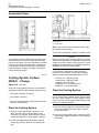
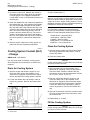
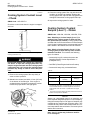
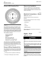
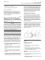
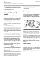
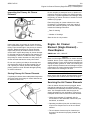
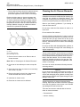
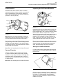
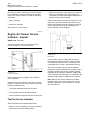
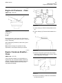
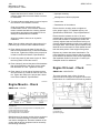
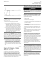
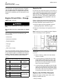
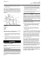
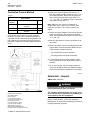
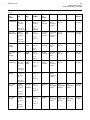
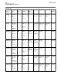
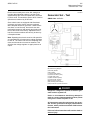
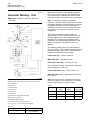
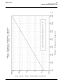
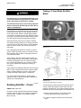
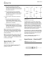


![Manuale Officina [ ITA ] Yamaha R1 2002-2003](http://vs1.manualzilla.com/store/data/006110674_1-52d32bbc9127defc0419b49b1226ec2b-150x150.png)