1
SEBU7147-05
An inspection of the turbocharger can minimize
unscheduled downtime. An inspection of the
turbocharger can also reduce the chance for potential
damage to other engine parts.
Note: Turbocharger components require precision
clearances. The turbocharger cartridge must
be balanced due to high rpm. Severe Service
Applications can accelerate component wear.
Severe Service Applications require more frequent
inspections of the cartridge.
Removal and Installation
145
Maintenance Section
Varistor - Test
5. Inspect the bore of the turbine housing for
corrosion.
6. Clean the turbocharger housing with standard
shop solvents and a soft bristle brush.
7. Fasten the air inlet piping and the exhaust outlet
piping to the turbocharger housing.
i01494879
Varistor - Test
SMCS Code: 4466-081
For options regarding the removal, installation, repair
and replacement, consult your Caterpillar dealer.
Refer to the Service Manual for this engine for the
procedure and specifications.
Cleaning and Inspecting
1. Remove the exhaust outlet piping and remove
the air inlet piping from the turbocharger. Visually
inspect the piping for the presence of oil. Clean
the interior of the pipes in order to prevent dirt
from entering during reassembly.
2. Turn the compressor wheel and the turbine wheel
by hand. The assembly should turn freely. Inspect
the compressor wheel and the turbine wheel for
contact with the turbocharger housing. There
should not be any visible signs of contact between
the turbine wheel or compressor wheel and the
turbocharger housing. If there is any indication of
contact between the rotating turbine wheel or the
compressor wheel and the turbocharger housing,
the turbocharger must be reconditioned.
3. Check the compressor wheel for cleanliness.
If only the blade side of the wheel is dirty, dirt
and/or moisture is passing through the air filtering
system. If oil is found only on the back side of the
wheel, there is a possibility of a failed turbocharger
oil seal.
The presence of oil may be the result of extended
engine operation at low idle. The presence of oil
may also be the result of a restriction of the line for
the inlet air (plugged air filters), which causes the
turbocharger to slobber.
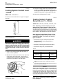
4. Use a dial indicator to check the end clearance
on the shaft. If the measured end play is greater
than the Service Manual specifications, the
turbocharger should be repaired or replaced.
An end play measurement that is less than the
minimum Service Manual specifications could
indicate carbon buildup on the turbine wheel. The
turbocharger should be disassembled for cleaning
and for inspection if the measured end play is less
than the minimum Service Manual specifications.
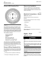
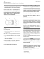
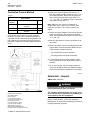
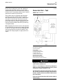
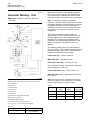
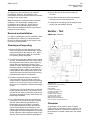
Illustration 105
g00677004
PMPE Generator Wiring Diagram
(CR1-CR6) Diodes
(CR7) Varistor
(L1) Exciter field (stator)
(L2) Exciter armature (rotor)
(L3) Main field (rotor)
(L4) Main armature (stator)
(L5) Pilot exciter armature
(PM) Permanent magnet
(RFA) Rotating field assembly
(CST) Customer supplied transformer
Ohmmeter
An ohmmeter can be used to check a varistor
(CR7). Place an ohmmeter across the varistor. The
resistance should be a minimum of 15000 ohms. If
the resistance is less than 15000 ohms, the varistor
is faulty.







![Manuale Officina [ ITA ] Yamaha R1 2002-2003](http://vs1.manualzilla.com/store/data/006110674_1-52d32bbc9127defc0419b49b1226ec2b-150x150.png)