1
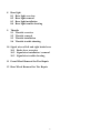
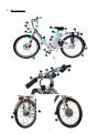
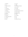
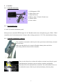
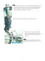
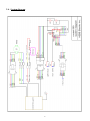
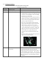
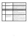
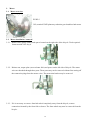
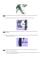
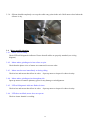
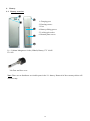
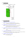
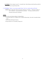
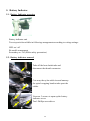
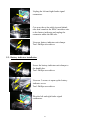
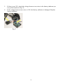
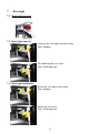
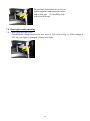
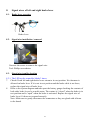
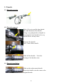
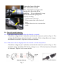
HEBB E-BIKES
ELECTROGLIDE 500
TECHNICAL SERVICE MANUAL
Index
1
Bike overview
2
Controller
2.1 Controller overview
2.2 Part identification
2.3 Controller installation / removal
2.4 System diagram
2.5 Self diagnostic indicator
3
Motor
3.1 Motor overview
3.2 Motor installation / removal
3.3 Motor maintenance
3.4 Motor trouble shooting
4
Battery
4.1 Battery overview
4.2 Battery removal
4.3 Battery installation
4.4 Wire diagram
4.5 Battery trouble shooting
4.6 Battery testing unit
5
Charger
5.1 Charger overview
5.2 Charging protocol
5.3 Charger trouble shooting
6
Battery indicator
6.1 Battery indicator overview
6.2 Battery indicator removal
6.3 Battery indicator installation
6.4 Battery indicator trouble shooting
7
Head light
7.1 Head light overview
7.2 Head light installation / removal
7.3 Head light trouble shooting
1
8
Rear light
8.1 Rear light overview
8.2 Rear light removal
8.3 Rear light installation
8.4 Rear light trouble shooting
9
Throttle
9.1 Throttle overview
9.2 Throttle removal
9.3 Throttle installation
9.4 Throttle trouble shooting
10 Signal wires of left and right brake lever
10.1 Brake lever overview
10.2 Signal wire installation / removal
10.3 Signal wire trouble shooting
11 Front Wheel Removal for Tire Repair
12 Rear Wheel Removal for Tire Repair
2
3
1. Bike Overview
11
10
16
9
8
17
18
15
19
14
12
13
6
1
5
3
4
2
7
23
21
22
24
25
20
27
26
28
4
1 Mudguard
15 Seat post
2 Rim
16 Saddle
3 Crank/Chain wheel
17 Seat folding mechanism
4 Pedals
18 Rear carrier
5 Chain guard
19 Rear light
6 Suspension fork
20 Left brake lever
7 Disk brake
21 Digital speedometer/odometer
8 Front LED light
22 Battery indicator
9 Head tube
23 Right brake lever
10 Brake wire
24 Throttle
11 Head stem
25 Gear shifter
12 Aluminum alloy frame
26 Gears
13 Controller
27 Chain
14 Battery
28 Brushless DC motor
5
2. Controller
2.1. Controller Overview
1. Self diagnostic LED
2. Motor phase wires
3. Motor hall wires
4. Battery gauge / Throttle / Brake lever
5. Motion sensor
6. Power cables
2.2. Part Identification
C1-9923 (20 mile/hr maximum speed)
Microprocessor controlled PWM output for 36V Brushless hub motor with planetary gears, Ebike / EPAC
controller unit. Overload protection 20 amps, under-voltage protection 31.5V. Die cast aluminum casing.
2.3. Controller installation / removal
The controller is mounted on the bicycle in the space between the battery slot and
the rear wheel.
Make sure that the bicycle is turned off and the battery taken out before
proceeding with the removal of the controller.
Turn over the bicycle on a clean soft surface or mount it on a bicycle repair
stand during the operation to prevent surface scratches and damage.
Disconnect all wires attached to the controller. You will find these wires on
the underside center of the bicycle (below the battery slot base plate).
6
Note!
1. On some bicycles, the motor wires from the controller leads all the way to
the front fork as shown, in some cases the wires are threaded through the
frame cable guides. It is then necessary to cut away the connectors to
continue with the dismantling of the controller.
2. Release the controller unit holding screws from the battery slot.
2
3. Release the screws and nuts of the chain
guard (if any) and dislodge the chain to push
the controller out towards the right of the
bicycle.
Note!
On some bicycles the chain guard is secured
using both screws and bolts (use 4 mm hex key).
3
7
2.4. System diagram
8
2.5. Self-diagnostic indicator
LED blinks
Always on
Model 500 Trouble Shooting Guide
(Controller version # 9923)
Problem
Solution
Function normal
2 times
No such signal
3 times
Brake lever cut-off in contact
a. Make sure the throttle rock switch is on at “I”
meaning the bike is ready to run. When this switch
is off at “O”, the LED blinks 3 times even though
the brake lever is functioning.
b. Check if both brake levers are returned to their rest
position. No clearance is allowed on brake lever. If
a lever is not in rest position and the brake cable is
not loose, replace the brake lever.
c. Refer to the system diagram and take apart the
battery gauge checking the contacts of both sides
brake levers by a multi-meter. The contact is
“closed” when the brake is in rest position and is
“open” when the brake is activated. Replace the
brake lever if the levers do not perform as above.
NOTE: Make sure to gently disconnect the
connector as they are glued with silicone to the
board.
d. Replace the battery gauge if the above processes are
all good and the light still blinks.
Fig.1
4 times
Throttle does not return to
zero position
The throttle should return to the rest position by
twisting the throttle all the way to the end, and
releasing. Turn off the bike and turn on power again. If
the LED still blinks, replace throttle. Note: You may
be able to get the throttle to return to the rest position by
slightly loosening the 2 mm bolt holding the throttle to
the handlebar.
9
5 times
No motor movement when
throttle is turned.
a. Make sure the throttle inside circuit is not wet.
Remove the throttle and let it dry. Requires several
hours or up to 2 days to dry depending on how wet
the throttle is. (90% error lies at throttle, very few
fail at battery gauge).
b. Please refer to the system diagram and disconnect
connectors between throttle and battery gauge. Use
a multi-meter to verify if there is a short circuit at
the throttle connector among first 3 pins. The 1st pin
(green for signal), 2nd pin (black for ground), 3rd pin
(red for 5V).
c. Placing probes on 1st pin + 2nd pin, 1st pin + 3rd pin,
2nd pin + 3rd pin. If there is short circuit, replace
throttle. Otherwise, replace battery gauge.
6 times
Low voltage
Charge the battery. This is a warning signal when
battery voltage drops below 30.5V. Bike is
functioning but user needs to charge the battery ASAP.
The blinks will stop once the battery is charged up to
34V. If voltage is below 20V, red LED light will be
off and unable to activate controller.
7 times
Excessively high voltage
The battery voltage is above 44V and the battery should
be replaced.
8 times
Hall sensor in hub motor
breaks off
Please refer to the system diagram and disconnect the 5
pins hall sensor connector. Make sure every pin is clean
and mounted firmly. Reconnect the connectors securely.
Replace the motor if the above does not work.
9 times
Failure of supply 3 phase
wires
a. Please refer to the system diagram and disconnect the
3 motor phase wire connectors after the connector
housings are removed as Fig. 2.
Fig. 2
Fig. 3
b. Using a multi-meter to verify if these 3 cables are
broken by placing probes on A): yellow + green B):
yellow + blue C): green + blue. If the ohms values
among any 2 of these 3 cables are unlimited value,
replace motor. See Fig. 3.
10
10 times
Controller temperature high,
thermostat activated
Cool down the controller ASAP. The controller
temperature protection is activated. Motor is able to
continue to work, but the current will be automatically
reduced to reduce the load and cool down controller.
11 times
Thermostat failure
Replace the controller. The thermostat is to protect the
controller from high temperature. The controller can
still drive the motor but it may be burned if temperature
increases too high.
12 times
Controller failure
Replace controller. Motor cannot be activated.
2+3 times
Controller failure
Replace controller. Motor cannot be activated.
3+4 times
Motor stalled
a. Make sure there isn’t any obstacle to prevent the
motor from turning.
b. Switch key off and on again to reboot the bike. An
extremely high load will stall the motor. Power
will be cut off if overload protection is activated.
3+5 times
Supply 3 phase wires broken
a. Please refer to the system diagram and disconnect the
(This symptom will show
only when the power is on
and throttle is twisted.)
3 motor phase wire connectors after the connector
housing is removed as Fig. 2.
b. Using a multi-meter to verify if these 3 cables are
broken by placing probes on A): yellow + green B):
yellow + blue C): green + blue. If the ohms values
among any 2 of these 3 cables are an unlimited value,
replace motor. See Fig. 3.
11
3. Motor
3.1. Motor overview
EZ-DP-3
36V, nominal 350W planetary reduction gear brushless hub motor.
3.2. Motor installation / removal
3.2.1. Remove nut, spring washer, and spacer located on the right side of the bicycle. Tools required:
19mm wrench / Hex key 4.
3.2.2. Release nut, torque plate (screwed onto fork) and spacer on the left side of bicycle. The motor
wires are threaded through these parts. These parts may not be removed without first cutting off
the connection plugs from the motor wires. The protection bracket may be removed.
3.2.3. If it is necessary to remove front hub wheel completely away from the bicycle, remove
connections located by the front fork as shown. The front wheel may now be removed from the
bicycle.
12
Note: When reinstalling the bicycle remember to fit front hub motor wheel in the correct direction.
3.2.4. Release all 6 screws on hub motor cover. Tools required: Philips head screwdriver.
Note: Releasing screws will detune spoke tension. Remember to recalibrate spokes on wheel after
installation.
3.2.5. Knock axle as shown on the picture to release hub motor from casing. Tools required: Rubber
mallet. Remove hub motor.
Note: 1. Hub motor should be worked on in a clean environment to avoid particles from entering
sensitive electronic equipment.
2. Ensure while working or when placing away the hub motor not to put weight or pressure on the
axle to prevent damage of the axle.
13
3.3. Motor maintenance
3.3.1. All motor parts are not serviceable by dealers with the exception of gears. Gears servicing is
limited to re-greasing the gears or replacement of gears. Any modification or reparation work done
without explicit consent of Hebb will immediately void warranty.
3.3.2. Apply silicone grease on gears and gear ring with a soft brush as shown on the pictures above.
3.3.3. Removal of planetary gears: Remove washer. Tools required: Snap ring pliers.
3.3.4. Use Snap ring pliers to remove snap ring – Apply the 2 pointed ends of the snap ring pliers into
the holes located in the snap ring. Gently and firmly press the plier’s handles to enlarge the ring
out of its groove. Remove the snap ring out and over the axle.
3.3.5. To prevent water from leaking into the motor core, apply silicone as shown.
14
3.3.6. Silicone should completely cover up the cable entry point in the axle. Refit motor wheel when the
silicone is dry.
3.4. Motor trouble shooting
3.4.1. Motor is not working
Check LED self-diagnostic indicator. Ensure that all cables are properly attached (see wiring
diagram).
3.4.2. Motor makes grinding noise but refuses to spin.
Check that the phase wires of motor are connected in correct order.
3.4.3. Motor runs but cuts immediately or during riding.
Check wires and ensure that all are in order. Open up motor to inspect for short circuitry.
3.4.4. Motor makes grinding noises throughout ride.
Open up motor to examine planetary gears for any damage or misalignment.
3.4.5. LED self-diagnostic indicator flashes 8 times.
Check wires and ensure that all are in order. Open up motor to inspect for short circuitry.
3.4.6. LED does not blink, motor does not operate.
Check to insure throttle is working.
15
4. Battery
4.1. Battery overview
1
3
2
4
5
1. Charging port
2. Housing screws
3. Fuse
4. Battery sliding groove
5. Locking pin socket
6. Bottom plate screws
6
Li+ / Lithium Manganese Oxide (LiMnO) Battery 37V 10AH
E2 / 002
30A Fuse and fuse cover
Note: There are no distributor serviceable parts in the Li+ battery. Removal of the warranty sticker will
void warranty.
16
4.2. Wiring Diagram
Wiring diagram for LiMnO Battery 37V 10AH
LiMnO
Battery
37V 10AH
4.3. Battery Trouble Shooting
4.3.1. Problem: Battery does not fit properly into holder.
Solution: 1. Remove battery and realign it along the battery grooves.
2. If fitting is too tight, apply grease on grooves for lubrication.
4.3.2. Problem: Battery is in holder but the key does not turn.
Solution: 1. Push battery firmly down and ensure that it is securely in place.
2. Check the alignment of battery locking socket and the pin.
3. Ensure that the correct key is used for the bicycle.
4.3.3. Problem: Battery is in holder, key is at “on” position but there is no power.
Solution: 1. Ensure that the battery is charged, battery pins are not damaged, and fuse is not
blown.
2. Check integrity of power cables (Refer to the system diagram).
4.3.4. Problem: Battery pin is damaged.
Solution: Refer to battery wiring diagram. Remove fuse before attempting any repair of the pins.
Refer to battery bottom plate for positive and negative wires.
4.3.5. Problem: Li+ battery cannot be charged.
Solution: 1. Ensure that the fuse is intact.
2. Use a different charger.
17
CAUTION: Do not attempt to open Li+ to trouble shoot. Record battery details and keep aside for
future inspection by Hebb.
4.3.6. Problem: Battery is not giving enough mileage / has lower capacity than specification.
Solution: Be sure the battery has been properly charged several times. Warranty for battery is
80% of DOD for 1 year from the date of purchase. The battery must be tested to
determine the amount of discharge.
NOTE:
1. Use the correct battery charger to charge battery.
2. Charge the battery for 30 minutes after 3 months without using, 1 hour after 6 months without
using;
3. Do not fully discharge the battery.
4. Keep batteries in a cool and dry storage area.
18
5. Charger
5.1. Charger overview
Lithium Ion battery charger
2 Amps, smart charge maximum charge time: 4-5 hours. Do not attempt to use Li+ charger
with other battery types. Always ensure voltage is set correctly to your country’s
specification.
5.2. Charging protocol
For optimum and safe charging, charge battery in a clean, cool and dry place. Ensure
voltage on charger is set correctly and fuse is working and secure. Plug power cord into
wall socket. Plug charger to battery and then turn on charger. Red light indicates
charger is “on”. Yellow light indicates battery is charging. Green light indicates charging
has stopped.
5.3. Charger Trouble shooting
5.3.1. Charger does not light up
Ensure that voltage has been set correctly. Ensure that the 10A fuse has not blown, replace
if necessary. Ensure that power cord is fitted in properly and in good condition.
5.3.2. Charger yellow light is blinking
The charger is sensitive to movement, temperature and voltage drop. Switch off charger
and retry using the protocol described above.
5.3.3. After retrying charging protocol, problem persists
Inspect battery fuse. There are no distributor serviceable parts on the Lithium Ion battery.
Replace battery if necessary.
19
5. Battery Indicator
5.1. Battery Indicator overview
Battery indicator unit
Two step switch available in following arrangements according to wiring settings:
LED on / off
Bi-model arrangement
Secondary on / off (Ebike safety precaution)
5.2. Battery indicator removal
Take off the heat shrink tube and
disconnect the throttle connector.
Cut away the nylon cable ties and unwrap
the spiral wrapping band to take apart the
cables.
Unscrew 3 screws to open up the battery
indicator cover.
Tool: Phillips screwdriver
20
Unplug the left and right brake signal
connectors.
Cut away the nylon cable ties and shrink
tube that connects the EPAC interface wire
to the battery indicator and unplug the
connector under the BB axle.
Unscrew battery indicator unit clamps.
Tool: Phillips screwdriver
5.3. Battery indicator installation
Screw the battery indicator unit clamps to
the handle bar.
Tool: Phillips screwdriver
Unscrew 3 screws to open up the battery
indicator cover.
Tool: Phillips screwdriver
Plug the left and right brake signal
connectors.
21
Screw 3 screws to close the battery
indicator cover.
Tool: Phillips screwdriver
Connect the throttle connector then cover
the heat shrink tube.
Use the nylon cable ties and the spiral
wrapping band to tie the cables together.
Tie and wrap the cables along the
underside of frame. Connect the connector
from the controller and covered by the
heat shrink tubes around the BB axle.
5.4. Battery indicator trouble shooting
5.4.1. Battery indicator is not responding
Ensure that problem is not power failure. Replace the battery indicator in case of
malfunction.
The battery indictor has no serviceable parts. Insure that all wiring is intact and in
working condition. If the problem persists, replace entire battery indicator.
22
6.
Head light
6.1. Head light overview
Head light
6.2. Head light installation / removal
Unscrew the head light from the frame.
Tool: Allen wrench + Spanner
6.3. Head light trouble shooting
6.3.1. Head light does not work.
1. Make sure the switch on the battery indicator is “ON”.
2. Open up the head light and check that the wires have good connection.
3. Check the voltage between two wires is 36V (as two yellow marks on Fig. 1).
4. If the voltage between two wires is 36V, the head light is damaged. Replace head
light.
Fig. 1
23
5.
6.
If there is not 36V, check the voltage between two wires in the battery indicator (as
two yellow marks on Fig. 2).
If the voltage between two wires is 36V, the battery indicator is damaged. Replace
battery indicator.
Fig. 2
24
7.
Rear light
7.1. Rear light overview
Rear light
7.2. Rear light removal
Unscrew the rear light from the frame.
Tool: Spanner
De-soldering the two wires.
Tool: Soldering iron
7.3. Rear light installation
Screw the rear light to the frame.
Tool: Spanner
Solder the two wires.
Tool: Soldering iron
25
Put the heat shrink tubes to cover two
soldering points and shrink the tubes
with a heat gun. Or carefully wrap
with electrical tape.
7.4. Rear light trouble shooting
7.4.1. Rear light does not work.
Checking the voltage between the two wires is 36V (refer to Fig. 1). If the voltage is
36V, the rear light is damaged. Change rear light.
Fig. 1
26
8.
Signal wires of left and right brake lever
8.1.
Brake lever overview
Brake lever
8.2.
Signal wire installation / removal
Unscrew the screw to remove the signal wire.
Tool: Phillips screwdriver
8.3.
Signal wire trouble shooting
8.3.1. The LED on the controller blinks 3 times.
7. Check if both left and right brake levers return to its rest position. No clearance is
allowed on brake lever. If it is not in rest position and the brake cable is not loose,
replace the signal wire of brake lever.
8. Refer to the system diagram and take apart the battery gauge checking the contacts of
both sides brake levers by a multi-meter. The contact is “closed” when the brake is in
rest position and is “open” when the brake is activated. Replace the signal wire of
brake lever if it does not respond correctly.
Note: Make sure to gently disconnect the connectors as they are glued with silicone
to the board.
27
9. Throttle
9.1. Throttle overview
Throttle
9.2. Throttle removal
Take of the wire and the heat shrink
tube and disconnect the throttle.
Using a very sharp knife is helpful in
removing the heat shrink but be very
careful not to cut any wires.
Unscrew the throttle.
Tool: 2 mm Allen wrench
Slide off the throttle. Note the
routing of the throttle wires.
9.3. Throttle installation
Slide on the replacement throttle.
Route the throttle wire the same as the
original throttle.
28
Tighten the 2mm Allen bolt.
Tool: 2mm Allen wrench
Note: Only tighten enough so the
throttle does not slide off the
handlebar. If over-tightened, it may
prevent the throttle spring from
properly working.
1. Connect the connector.
2. Wrap connection with electrical
tape.
3. Replace the wire ties to secure the
wires.
9.4. Throttle trouble shooting
9.4.1. The motor does not move when the throttle is twisted.
Check the voltage of pin 1 (throttle) on the throttle connector (refer to Fig. 1). The
voltage should change when the throttle is twisted. If the voltage does not change,
the throttle is defective. Replace with a new throttle.
9.4.2. The motor moves slightly when the throttle is in the off position.
Check the voltage of pin 1 (throttle) on the throttle connector (refer to Fig. 1). The
nominal voltage should be 0.9V. If the voltage is over 1.2V, the function of throttle
is abnormal. Replace with a new throttle.
Fig. 1
29
10. Signal wires of left and right brake lever
10.1. Brake lever overview
Brake lever
10.2. Signal wire installation / removal
Unscrew the screw to remove the signal wire.
Tool: Phillips screwdriver
10.3. Signal wire trouble shooting
10.3.1. The LED on the controller blinks 3 times.
9. Check if both left and right brake levers return to its rest position. No clearance is
allowed on brake lever. If it is not in rest position and the brake cable is not loose,
replace the signal wire of brake lever.
10. Refer to the system diagram and take apart the battery gauge checking the contacts of
both sides brake levers by a multimeter. The contact is “closed” when the brake is in
rest position and is “open” when the brake is activated. Replace the signal wire of
brake lever if it does not respond correctly.
PS: Make sure gently disconnect the connectors as they are glued with silicone to the
board.
30
11 Front Wheel Removal for Tire Repair
1. Remove screws on torque plate using 4mm hex key.
2. Remove nut using 19mm (or adjustable) wrench on axle.
3. Remove all the small parts, nuts, washers, torque plate, etc.
31
4. Cut nylon ties with cutter or scissor.
5. Un-screw and remove connector casing cover
6. Disconnect cable
32
7.
Disconnect wire
8. Loosen nut on opposite side using a 19mm or adjustable wrench.
9. Take wheel out of the fork and proceed to change inner tube or tire.
33
10. Put wheel back in place and tighten both sides evenly, a little on each side at a time.
Reconnect the cables and wires. Check alignment of the disc brakes.
34
12 Rear Wheel Removal for Tire Repair
1. Shows gear shifting cable
2.
Grip cable with fingers or pliers.
3.
Release shifting cable and nut from hub by pulling backward and outward.
35
4. Release nut and bolt assembly from brake assembly using 10mm wrench and nut driver.
At this point, you should also remove the axle nuts and torque washer.
5. Pull back and release chain from hub sprocket.
6. Release rear wheel from frame to change tire or inner tube
36
7. Put rear wheel back on and chain on sprocket.
8. Put torque washer back into position
9. Tighten nuts of both sides evenly and slightly ( do not tighten yet )
37
10. Pull wheel backward with one hand and the other holding against rear stay so that chain has slight tension is
not loose.
11. Align shifting cable into groove of the hub and snap the nut back into position
38