1
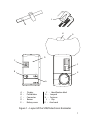
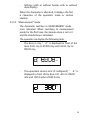
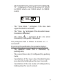
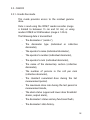
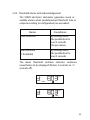
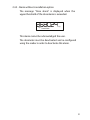
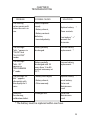
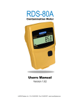
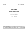
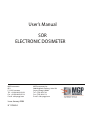
User's Manual
SOR
ELECTRONIC DOSIMETER
MGP Instruments
BP 1
F-13113 Lamanon
Tél. : +33 (0)4 90 59 59 59
Fax : +33 (0)4 90 59 55 18
E-mail : [email protected]
Issue: January 2004
N° 129442A
MGP Instruments Inc.
5000 Highlands Parkway, Suite 150
Smyrna, Georgia 30082
Tel : (770) 432 2744
Fax : (770) 432 9179
E-mail : [email protected]
TABLE OF CONTENTS
CHAPTER I - CHARACTERISTICS ..................................... 5
1.1 - GENERAL CHARACTERISTICS ............................... 5
1.1.1 - Purpose of the equipment .................................. 5
1.1.2 - Layout of the SOR/R electronic dosimeter........ 5
1.1.3 - Recommended operators ................................... 9
1.2 - DIMENSIONS ............................................................. 9
1.2.1 - SOR/R electronic dosimeter ............................... 9
1.3 - ENVIRONMENTAL CHARACTERISTICS ................. 9
1.4 - ELECTROMAGNETIC ENVIRONMENTAL
CONDITIONS........................................................... 10
1.5 - RADIATION EFFECTS ............................................ 10
1.6 - PERFORMANCE...................................................... 10
1.6.1 - Start-up............................................................... 10
1.6.2 - Warm-up ............................................................. 10
1.6.3 - Deactivation ....................................................... 10
1.6.4 - Data storage....................................................... 11
1.7 - ENVIRONMENTAL LIMITATIONS........................... 11
1.8 - SAFETY RULES RELATING TO
THE EQUIPMENT .................................................... 11
1.9 - PERSONNEL SAFETY ............................................ 11
CHAPTER II - USE IN NORMAL CONDITIONS ................ 13
2.1 - PROCEDURES AND PRELIMINARY CHECKS ...... 13
1
2.2 - INSTRUCTIONS FOR USE ...................................... 13
2.2.1 - Preliminary checks ............................................ 13
2.2.2 - Operating checks .............................................. 13
2.2.3 - Dosimeter / Reader-Recorder interaction........ 13
2.2.4 - Data stamping.................................................... 14
2.2.5 - Storage - Pause - Measurement ....................... 14
2.3 - CHECKS .................................................................. 18
2.3.1 - Hands-free mode ............................................... 18
2.3.2 - Manual read mode ............................................. 19
2.3.3 - Serial link............................................................ 19
2.4 - ALARMS .................................................................. 19
2.4.1 - Buzzer................................................................. 19
2.4.2 - Threshold alarms with acknowledgement....... 20
2.4.3 - Alarm without cancellation option ................... 21
CHAPTER III - TROUBLESHOOTING ............................... 23
CHAPTER IV - MAINTENANCE......................................... 25
4.1 - MAINTENANCE ....................................................... 25
4.2 - RADIOLOGICAL DECONTAMINATION.................. 26
4.2.1 - Recommended tools and materials ................. 26
4.2.2 - Preliminaries to be carried out by personnel.. 26
4.2.3 - Equipment decontamination ............................ 26
4.3 - CHEMICAL DECONTAMINATION .......................... 27
4.3.1 - Recommended means....................................... 27
4.3.2 - Preliminaries to be carried out by personnel.. 28
4.3.3 - Equipment decontamination ............................ 28
2
FIGURES
Figure n°
Page
1 - Layout of the SOR/R Electronic Dosimeter ........... 7
3
4
CHAPTER I
CHARACTERISTICS
1.1 - GENERAL CHARACTERISTICS
1.1.1 - Purpose of the equipment
The SOR/R electronic dosimeter is used for measuring
several types of radiation to which the user may be
exposed:
−
Ambient and artificial X and Gamma,
−
Residual Gamma,
It is a rugged equipment specifically designed to fulfill
the military forces operational conditions.
An original hands-free mode enables the data
exchange with the XOM/R reader even through the
NBC clothes.
1.1.2 - Layout of the SOR/R electronic dosimeter
The SOR/R electronic dosimeter is equipped with a
protective dust and liquid-proof casing.
5
According to the options selected, it can be fitted with a
lanyard for chest wear, a velcro arm band to be worn
over the protective clothing, or a clip.
−
The front panel of the SOR/R electronic dosimeter
includes:
•
•
−
a pushbutton (B) for data selection and alarm
acknowledgement,
•
a smart-card type connector(C),
•
a buzzer (audible alarm) (D).
The rear panel includes:
•
•
−
an LCD (A) for data and user id display,
battery access via a screwed-on cover (E). The
cover includes a slot for screwing/unscrewing
using a coin or flat-blade screwdriver,
an identification label (F).
The top of the unit includes a hole for inserting the
lanyard (G) and a fastener (H) for safety release.
A groove is also included for attaching the clip.
1.1.2.1 - Display
The dosimeter
characters.
can
display
6
alphanumeric
It is designed for easy display reading.
The display can also be equipped with an optional
back-lighting system.
It can also be blanked.
6
J
K
H
G
D
C
F
B
E
A
A
B
C
D
E
–
–
–
–
–
Display
Pushbutton
Connector
Buzzer
Battery cover
F – Identification label
G – Lanyard
H – Fastener
J – Clip
K – Arm band
Figure 1 – Layout of the SOR/R electronic dosimeter
7
To read the display:
The operator must raise the dosimeter horizontally if
it is worn around the neck.
The operator must hold up his arm if the dosimeter
is worn on the arm band.
1.1.2.2 - Pushbutton
The pushbutton enables display of the following
information:
−
The operator's name when pushed once,
−
The equivalent dose output when pushed twice
(according to configuration).
It enables cancellation of:
−
The lower dose alarm buzzer (pre-alarm) when
held down for over 3 seconds,
−
The dose rate alarm buzzer when held down for
over 3 seconds (according to configuration).
1.1.2.3 - Connector
The connector enables connection to the XOM/T
reader-recorder and to external devices.
1.1.2.4 - Buzzer
The buzzer sound level pressure 80 dB to 90 dB at
30 cm in front of the dosimeter. Frequency is 5.5 to
5.8 kHz.
8
1.1.2.5 - Power supply
The SOR/R electronic dosimeter operates using a
standard Lithium battery format CR2450.
1.1.2.6 - Arm Band
A quick-fitting velcro arm band is used for arm wear
(ref. K – Fig.1).
The arm band includes a transparent window for
easy display reading and pushbutton location.
1.1.3 - Recommended operators
The SOR/R electronic dosimeter's easy operation
requires only brief instructions for non-specialized
personnel.
1.2 - DIMENSIONS
1.2.1 - SOR/R electronic dosimeter
−
Height
: 80.4 mm,
−
Width
: 48 mm,
−
Depth
: 9.6 mm,
−
Weight
: 55 g,
−
Lanyard
: 80 cm.
1.3 - ENVIRONMENTAL CHARACTERISTICS
The SOR/R electronic dosimeter fulfill the STANAG
2895 for the all climate zones.
SOR/R is qualified according to MIL-STD-810 standard.
9
1.4 - ELECTROMAGNETIC ENVIRONMENTAL
CONDITIONS
The dosimeter performance is not affected by the
following environments:
−
Electric field from 10 kHz to 10 GHz,
−
Magnetic field from 10 kHz to 250 kHz.
−
Electromagnetic pulse (EMP).
1.5 - RADIATION EFFECTS
The SOR/R includes a protection against the TREE
effects for initial gamma and neutron radiations.
1.6 - PERFORMANCE
1.6.1 - Start-up
The reader-recorder is used to switch the dosimeter
from "PAUSE" to "MEASUREMENT" mode.
1.6.2 - Warm-up
After start-up, the SOR/R electronic dosimeter is ready
for use in under 5 seconds even in the least favourable
environmental conditions.
1.6.3 - Deactivation
Once the mission is complete and the data has been
read by the reader, the dosimeter switches back from
"MEASUREMENT" to "PAUSE" mode.
10
1.6.4 - Data storage
All data is stored in the dosimeter's memory for over 10
years, even in the absence of a battery.
Dose increments are recorded at user selectable
intervals of 10 seconds, 1 minute, 10 minutes, 1 hour
or 24 hours, as programmed by the reader. Recording
duration is 750 steps, with dose increment.
The data history is circular type; i.e. old data is
overwritten by the most recent data.
All events and anomalies are recorded and dated
systematically in the data history.
1.7 - ENVIRONMENTAL LIMITATIONS
Operating temperature
: - 21 °C to + 60 °C,
Storage temperature
:
- 40 °C to + 71 °C.
1.8 - SAFETY RULES RELATING TO THE EQUIPMENT
Not applicable.
1.9 - PERSONNEL SAFETY
The user is not exposed its any electrical risks
generated by the dosimeter.
11
12
CHAPTER II
USE IN NORMAL CONDITIONS
2.1 - PROCEDURES AND PRELIMINARY CHECKS
2.1.1 - Operator interaction
A variety of display options are available in each mode:
−
"PAUSE" mode,
−
"ALLOCATED" mode,
−
"MEASUREMENT" mode.
2.2 - INSTRUCTIONS FOR USE
2.2.1 - Preliminary checks
Check that a new battery is installed and that the
dosimeter is not in storage mode.
2.2.2 - Operating checks
The SOR/R electronic dosimeter is equipped with
operating indicators (2 dots on the display (:) which
flash continuously).
2.2.3 - Dosimeter / Reader-Recorder interaction
The dosimeter can be read and configured by the
XOM/T reader-recorder using two modes:
−
Without physical contact ("hands-free " mode),
−
With physical contact ("manual read" mode).
13
The " hands-free" mode enables the exchange of
stored data (dosimeter n°, operator's identity, doses,
output, etc.).
2.2.4 - Data stamping
The SOR/R electronic dosimeter is dated automatically
during interaction with the XOM/R reader.
2.2.5 - Storage- Pause– Measurement
2.2.5.1 - Stored mode
In this mode, the battery is not installed.
The arm bands are delivered in two batches of 5,
along with a technical guide.
Destorage consists of unpacking the dosimeter and
installing the battery (delivered in packs of 10).
Warning : The battery "+" must be inserted facing
towards the dosimeter.
The dosimeter switches to "PAUSE" mode after a
few seconds.
Note: Dosimeters stored with the battery removed
retain Gamma and Neutron doses plus configuration
data for a period of 10 up to years.
14
2.2.5.2 - "Pause" mode
Not allocated
Flashing colon
Hp
The dosimeter carries out self-tests every 10
minutes (data initialization and calibration integrity
tests, standard Gamma counting channel test, ASIC
test, battery test).
The dosimeter displays "PAUSE" if no faults are
detected. Failing this, the detected anomalies are
displayed alternately with "PAUSE".
The 2 flashing colon confirm that the dosimeter is
functioning properly.
Allocated
The allocation operation is carried out using the
XOM/T reader-recorder which configures:
−
The operator's name and number or section
identity (collective dosimeter),
−
The section composition,
−
The upper and lower dose alarm thresholds,
−
The equivalent dose rate alarm threshold,
15
−
Settings (with or without buzzer, with or without
dose display).
When the dosimeter is allocated, it displays the first
6 characters of the operator's name or section
identity.
2.2.5.3 - "Measurement" mode
The dosimeter switches to MEASUREMENT mode
once allocated. When switching to measurement
mode for the first time, the Gamma dose is set to 0
and the data history is initialized.
The operator can display the following data:
−
The dose in cGy; " d: " is displayed in front of the
dose 0.001 cGy to 99.999 cGy and 100.00 cGy to
999.99 cGy,
Hp
−
cGy
The equivalent dose in mSv (if configured); " d: " is
displayed in front of the dose 0.01 mSv to 999.99
mSv and 1000.0 mSv to 9999.9 mSv,
mSv
Hp
16
−
The equivalent dose rate in mSv/h (if configured);
"R: " is displayed in front of the value 0.01 mSv/h
to 999.99 mSv/h and 1000.0 mSv/h to 9999.9
mSv/h,
mSv/h
Hp
−
The " Dose Alarm " pictogram if the dose alarm
upper threshold is exceeded,
−
The " Dose ! " pictogram if the dose alarm lower
threshold is exceeded,
−
The " Rate !
" pictogram if the rate alarm
threshold (if configured) is exceeded.
The pictograms flash as follows: 2 seconds on / 2
seconds off.
By pressing the pushbutton, the operator displays:
−
The operator's name (first 6 characters) by
pushing once,
−
The current dose rate (if configured) by pushing
twice,
−
Cancellation of the lower dose threshold buzzer
(pre-alarm) by holding down for over 3 seconds,
−
Cancellation of the rate buzzer (if configured) by
holding down for over 3 seconds.
17
2.3 - CHECKS
2.3.1 - Hands-free mode
This mode provides access to the residual gamma
dose.
Data is read using the XOM/T reader-recorder (range
is limited to between 15 cm and 50 cm), or using
readers XOM/R or XOM markers (range is 1.20 m).
The following data is transmitted:
−
The dosimeter n° (serial n°),
−
The dosimeter type (individual or collective
dosimeter),
−
The operator's name (individual dosimeter),
−
The operator's number (individual dosimeter),
−
The operator's rank (individual dosimeter),
−
The name of the elementary section (collective
dosimeter),
−
The number of persons in the cell per rank
(collective dosimeter),
−
The standard cumulated dose during the last
measurement period,
−
The maximum dose rate during the last period in
measurement mode,
−
The alarm status (upper and lower dose threshold
alarms, output alarm),
−
The dosimeter's status and any functional faults,
−
The dosimeter's data history.
18
2.3.2 - Serial link
Main dosimeter data, such as standard cumulated
dose, maximum rate, alarm status and faults can be
retrieved by connecting an external device
(Maintenance Level 2) to the smart-card type
connector.
2.4 - ALARMS
2.4.1 - Buzzer
The buzzer, used to indicate an alarm or fault, can be
disabled during configuration using the XOM/T reader.
19
2.4.2 - Threshold alarms with acknowledgement
The SOR/R electronic dosimeter generates visual or
audible alarms when predetermined threshold (rate or
output according to configuration) are exceeded.
Alarms
Cancellation
Dose threshold
By holding down
the pushbutton for
over 3 seconds
(for pre-alarm).
Rate threshold
(1 threshold)
By holding down
the pushbutton for
over 3 seconds.
The alarm threshold violation indicator continues
nevertheless to be displayed (flashes 2 seconds on / 2
seconds off).
mSv
Hp
Dose
mSv
Hp
Rate
20
2.4.3 - Alarm without cancellation option
The message "Dose alarm" is displayed when the
upper threshold of the dose alarm is exceeded.
Hp
Dose Alarm
cGy
This alarm cannot be acknowledged the user.
The dosimeter must be deactivated and re-configured
using the reader in order to deactivate this alarm.
21
22
CHAPTER III
TROUBLESHOOTING
PROBLEM
The flashing
colon remain unlit
when the unit is in
use.
POSSIBLE CAUSES
Defective power
supply:
- Battery absent,
- Battery contacts
defective,
SOLUTIONS
Replace battery. *
Clean contacts.
- Inverted polarity.
Face battery " + "
towards the
dosimeter.
The message
"bAt -" appears in
"PAUSE" and
"ALLOCATED"
modes
Battery partially
discharged.
Foresee battery
replacement. *
The message
"bAt - XX"
appears in
"MEASUREMEN
T" mode
Battery partially
discharged with XX
hours from 15 to 00
residual autonomy at
25 °C.
Foresee battery
replacement. *
The message "dF
bAt " appears
alternately with
the display for 3
mins.
- Battery discharged,
Replace battery. *
- Battery absent,
Insert battery.
- Other anomaly.
Go to next
Maintenance
Level
Defective
functioning,
calibration defect.
Prolonged use.
Go to next
Maintenance
Level
* The battery must be replaced within one hour.
23
24
CHAPTER IV
MAINTENANCE
4.1 - MAINTENANCE
OPERATION
PERIODICITY
ITEMS REQUIRED
Battery
replacement.
Maintenance
Level 1 as
required
3 V CR 2450 LiMnO 2. or
Li-SOcl 2 battery type.
Lanyard
replacement.
Maintenance
Level 1 as
required.
Cord.
Fastener
replacement.
Maintenance
Level 1 as
required.
Fastener.
Battery cover
replacement.
Maintenance
Level 1 as
required.
Battery cover.
Cleaning
(equipment
uncontaminated).
Rag and alcohol.
Hook replacement.
Pin extraction tool.
NOTA : SOR/R is NATO codified
25
4.2 - RADIOLOGICAL DECONTAMINATION
4.2.1 - Recommended tools and materials
The following means may be used:
Rags and brushes,
−
Water,
−
Radiological decontamination solution for personnel,
−
Compressed air.
−
Standard cleaning means may also be used, given that
decontamination implies achieving cleanliness.
4.2.2 - Preliminaries to be carried out by personnel
Although radiological contamination decreases with
time it cannot be eliminated. The only decontamination
possible consists of removing radioactive dust or liquid
agents.
Consequently, personnel should avoid becoming
soiled. The protective clothing must be worn tightly
buttoned and snugly fitting at the wrists.
All pockets must be closed. In case of high
contamination, and by order, special clothing and
masks shall be used.
4.2.3 - Equipment decontamination
4.2.3.1 - Dry decontamination
This consists of chemical decontamination
according to the standard procedures for sensitive
equipment.
If the cause of the contamination is dry dust,
decontaminate using brushes and rags and if
possible use compressed air to remove the dust.
26
This operation requires the wearing of NBC protective
gear (clothing and mask).
IMPORTANT : The equipment must be decontaminated
to a residual level <5Bq/cm 2 for highly
toxic alpha emitters and <50Bq/cm 2 for
beta and alpha emitters with low
toxicity.
4.2.3.2 - Wet decontamination
In the case of wet contamination, clean externally
using rags, avoiding liquid ingress into the
equipment, then wash with soapy water or spirits.
4.3 - CHEMICAL DECONTAMINATION
The equipment must be decontaminated further to an
attack by a persistent toxic agent (in liquid form).
The equipment must be decontaminated as soon as
possible after the attack.
IMPORTANT : The longer decontamination is delayed,
the more the toxic product penetrates
the paintwork, thereby rendering
elimination increasingly difficult.
4.3.1 - Recommended means
The following means are required for decontamination:
−
Chemical decontamination solution for the
equipment,
−
Emergency chemical decontamination gloves,
−
Hot soapy water,
−
Rags for applying liquids.
27
4.3.2 - Preliminaries to be carried out by personnel
IMPORTANT : The wearing of breathing apparatus and
NBC protective gloves is imperative.
4.3.3 - Equipment decontamination
4.3.3.1 - Application of the liquid
Rub the equipment with a rag soaked in liquid,
concentrating on the most frequently handled parts.
Rinse thoroughly with water for one minute.
4.3.3.2 - Use of the F1 type emergency chemical
decontamination glove
Proceed as follows:
−
Tap the equipment with powder using the
powdered side of the glove, concentrating on the
most frequently handled parts,
−
Wipe carefully using the sponge side of the glove,
−
Repeat the above operations once.
This procedure is very effective on flat surfaces but
does not enable elimination of the toxic agent on
less accessible areas of the equipment. The glove
remains,
however,
the
best
available
decontamination method.
REMARKS:
Even if decontamination is carried out rapidly after
the attack, the toxic agent will probably not have
been eliminated totally.
The wearing of protective gloves remains necessary
when operating the equipment, due to risks of
residual contamination.
28