1
KORG D888
SERVICE MANUAL
TABLE OF CONTENTS
ASSEMBLY SKETCH (HOOKUP)
:2
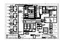
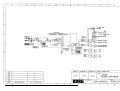
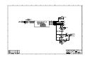
BLOCK DIAGRAM:3-4
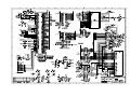
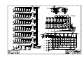
SCHEMATIC DIAGRAM:5-9
TEST MODE and INSPECTION:10-16
PARTS LIST:17-18
D888 TEST MODE & INSPECTION
Page 1/6
▼Needed Apparatus for test
1)Monaural standard chord x2-8(for INPUT-OUTPUT, for FOOT SW)
2)FOOT SW
3)Headphones
4)AC chord
5)S/P DIF optical cable
6)MIDI cable
7)D3200 (if you can prepare)
Note
Switch operation in the test mode
[REC]: Go to the next test
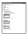
(1)TEST MODE INSPECTION
>Connect AC chord to D888
>Turn power on the switch at rear panel
.>Pushing [FF] and [PLAY], push [ON-STAND-BY]
Continue pushing [FF} and {PLAY]
After several seconds, following display will appear.
D888 TEST MODE
External Check
TEST01:SPEC.
HDD Volume : 37.3GB
SYSTEM
→*.*.* B000**
Then, take your fingers off from the switches.
Push [REC]
●TEST02 PHANTOM
In the LCD display,
External Check
TEST02:PHANTOM
STEP01:PHANTOM ON
Above display will appear.
>Confirm the LED of [PHANTOM] lit.
Push [REC]
In the LCD
External Check
TEST02:PHANTOM
STEP02:PHANTOM OFF
Above display will appear.
>Confirm the LED of [PHANTOM] turned off.
Push [REC]
Page 2/6
●TEST03 LED/SWITCH
STEP1:LED ALL-ON
>Confirmation of all LEDs lit, confirm LEDs are lighting like followings.
*HDD does not light.
Red light (SW) :PHANTOM、 OUTPUT ASSIGN、BOUNCE、REC/PLAY、EFFECT ON、MENU、
METRONOME、REC
Red light (LED) :STANDBY、UNDO、REDO、AUTO PUNCH、REHEARSAL、REPEAT(14 red LEDs)
Orange light (SW) :CH ON、1、2、3、4、5、6、7、8、MASTER (Orange 10 LEDs)
Green light (SW) :PLAY(4 LEDs)
White light
:LCDBack lightト
Push [REC]
STEP2:CLick
>Push [name] appears in the LCD display one by one, then confirm the SW and LED.
Regarding following switches, push twice or more.
>CH1-8, and MASTER, push twice each switch and confirm that LED changes from red to green.
>UNDO/REDO: push twice and confirm UNDO and REDO LED light red one by one.
>REC/PLAY MODE: push three times and confirm that AUTO PUSH, REHEARSAL,
REPEAT LED light one by one.
>PLAY: Push three times and the 4 LEDs light one by one.
Push [REC]
●LCD INSPECTION
Black dots are displayed in the LCD.
>Confirm that there are no chipped dot or uneven dot.
Push [REC]
All dots in the LCD disappeared.
>Confirm that the backlight is lighting not unevenly.
Push [REC]
●LCD CONTRAST INSPECTION
>"#" is displayed in the LCD, confirm the contrast changes.
Push [REC]
●TEST05 A/D
Rotate CH1 EQ GAIN "HIGH" from MAX to MINI and stop at the center click position.
>Confirm that the "HIGH" characters in the display are reversed.
The reversed characters means that the working of the volume is OK.
Same as above, test MID>LOW>EFFECT>PAN>Fader, one by one.
"EFFECT" and "Fader" have not the center click, so the test ends when MINI position is detected .
After all tests until Fader are OK , the LED of CH2 TRACK lights.
Same as above, proceed the tests until CH8.
After CH8 test, LED of MASTER lights and EFFECT PROGRAM INSPECTION begins.
Page 3/6
Move the EFFECT selector, then ">11"is displayed.
Adjust the EFFECT selector at the position of "11".
"Wait" is displayed, after some while, ">10"is displayed.
Move the EFFECT selector at the position of "10".
Same as above, move the selector to "displayed number"(6,2,1) after "WAIT".
After finished "1", proceed the tests PARAMETER, RTN, and MST.
*NOTE: In the A/D test, when the wrong VR was moved , and D888 read wrong value,
ERROR is displayed, in this case push[REW] then the test begin from the VR in the test.
"FSW" in the LCD display is the test of FOOT SW.
Connect foot switch to D888.
Push foot switch once.
>Confirm the characters "FSW" in the LCD is reversed.
Disconnect the foot switch.
Push [REC]
Followings are displayed in the LCD.
TEST06:EXIT
Power off = UNDO SW
Push [UNDO]
LCD display is cleared.
Test mode has finished.
Page 4/6
(2)NORMAL MODE INSPECTION
Push [ON-STANDBY], and turn power on.
Demo Song "Black Swan" is displayed.
>Connect standard monaural chords as following.
MONITOR OUT L -> INPUT 1
MONITOR OUT R ->INPUT 2
MASTER OUT L ->INPUT 3
MASTER OUT R->INPUT 4
INDIVIDUAL 5 -> INPUT 5
INDIVIDUAL 6 ->INPUT 6
INDIVIDUAL 7 ->INPUT 7
INDIVIDUAL 8 -> INPUT 8
>Confirm all TRIM knobs are at the position of "4".
●Test of Demo Song play
>Connect headphones to PHONE1 jack.
>Push [PLAY]
Demo Song playing begins.
>Rotate PHONE1 and listen at appropriate volume.
Confirm that the sound is not distorted or not including noise.
>Push [STOP]
>Pushing [STOP} and push [REW]
The counter in the LCD becomes to "00::00:00.000"
>Connect headphones to PHONE2 jack.
>Push [PLAY]
Demo Song playing begins.
>Rotate PHONE2 and listen at appropriate volume.
Confirm that the sound is not distorted or not including noise.
>Push [STOP]
>Pushing [STOP} and push [REW]
The counter in the LCD becomes to "00::00:00.000"
●INPUT/OUTPUT INSPECTION
>Confirm that MONITOR LEVEL KNOB (left of INDIVIDUAL 5) is set at "10"
When using standard monaural chords less than 8, do following inspection changing the chords.
>Push [PLAY]
Demo Song playing begins.
Rotate INPUT1-8TRIM to -60.
Confirm each PEAK LED lights.
After inspection of INPUT1-8, set theTRIM of 1-8 at +4.
>Push [STOP]
>Pushing [STOP} and push [REW]
The counter in the LCD becomes to "00::00:00.000"
>Disconnect standard monaural chords.
Page 5/6
●MIDI, S/P DIF INSPECTION
*Regarding MIDI S/P DIF INSPECTION
MIDI、S/P DIF INSPECTION is written by a premise of using D3200
Please do following inspection when you can use D3200.
When you can not prepare D3200, connect other external MIDI equipment
and some equipment with digital connection. And confirm the working by D888 user's manual
and other equipment's user's manual.
Turn power on D3200 refer to "Settings of D3200" page.
>Connect the AC chord to D888
>Turn power on by pushing rear POWER SWITCH.
STANDBY LED lights.
>Push ON right of STANDBY LED. (D888 starts.)
●S/P DIF INSPECTION
>Connect S/P DIF OUT of D888 to S/PDIF IN of D3200.
>Move up TRACK1,TRACK2,and MASTER fader of D3200 to "0"
>Set MONITOR LEVEL and PHONE LEVEL of D3200 to "0"
>Change to connect headphones from D888 to D3200.
Push [PLAY] of D888.
Move up D3200 headphone level appropriately, and confirm the D888's demosong output..
>Push [STOP] of D888.
>Pushing [STOP] and push [REW] of D888.
>Disconnect the digital cable.
●MIDI INSPECTION
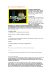
>Set D888 like followings. MIDI OUT setting)
1)Push [MENU] (EDIT MENU is displayed.)
2)Push ∇(DOWN) of CURSOR 4 times.
"5.MIDI OUT <>OFF" is displayed.
3)Push ▷(RIGHT) of CURSOR. "MTC" is displayed.
4) Push [ENTER/OK]
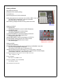
5)Push [LEVEL METER]
CURSOR
③
②
>Connect MIDIOUT of D888 to MIDI IN of D3200.
>Push [PLAY] of D3200.
"Waiting MTC" is displayed.
>Push [PLAY] of D888. (Demo song play begins.)
-The counter of D888 starts.
Confirm that the counter of D3200 is also working.
(After around 2 seconds display, D3200 starts. This is not malfunction.)
>Push [STOP] of D888.
>Confirm that the D3200 also stopped..
>Pushing [STOP] and push [REW] of D888.
(The counter of D3200 also becomes 00:00:00.000)
>Push [STOP] of D3200.
>Disconnect MIDI cable.
Page 6/6
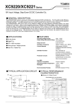
●Recover the D888 settings.
1)Push [MENU] (EDIT MENU is displayed.)
"5.MIDI OUT <>MTC" is displayed..
2) push ⊲ (left) of CURSOR. MTC changes to OFF.
3) Push [ENTER/OK]
4)Push △ (up) of CURSOR 4 times.
At 1.Track, "<>Copy " is displayed.
5)Push [LEVEL METER]
>Push [ON-STANDBY] of D888 until following display appears.
Shut Down:
AreYou Sure?
OK or CANCEL
After above display, take your fingers off from the switch.
>Push [ENTER/OK]
After around 10 seconds, LCD display disappears..
>Turn power off by rear power switch.
>Disconnect AC chord.
The Inspection completed.
CURSOR
④
②
Setting of D3200
Set D3200 as following.
(Example is from factory setting)
Turn power on.
Demo song [I'd Be A FOOL] is displayed.
●Using the joystick move the arrow in the LCD to "NEW", then click.
"44.1kHz/16bit" is displayed in reversed characters.
Move the arrow to "OK" then click.
After Working, display becomes the song which was made.
JOY STICK
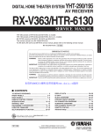
●Setting of S/P DIF
1) Push [MIXER]
The square CURSOR is at the CH INPUT/Submixer.
2) Push [MIXER] again.
The display becomes to Channel Assign.
The square CURSOR is at the CH1..
3) Rotate ENCODER to right and set display to S/P DIF L.
4) Push [ >] at the right of the joystick once.
CURSOR moves to CH2.
5)Rotate ENCODER to right and set display to S/P DIF R.
6) Push [SONG], display returns to the former screen.
7) Push TRACK1 and TRACK2 once for each.
The red LED lights.
③
Display of CH 1= S/P DIF L
Display CH 2= S/P DIF R
●Setting of MIDI
1) Push [SYSTEM MIDI]
2) Using the joystick, move the arrow in the display to MIDI/MMC, then click.
The screen of MIDI/MMC is displayed.
The setting of MTC MIDI Sync is checked at OFF.
3)Using the joystick and move the arrow to ○ of "MTC Slave", then click.
The check mark appears in "○ MTC Slave" and becomes reversed display.
"Chase Mode" under the " ○MTC Slave" is OFF.
4) Using the joystick and move the arrow to OFF, then click.
"OFF" changes to "ON"
5) Push [SONG]
LCD returns to SONG screen.
6) Pushing [SONG], and push {ENTER].
The setting is saved.
The preparation has finished.
⑤
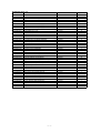
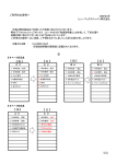
KORG D888 Parts List
Parts No.
Parts Name
Note
QTY
510313501001
LCD FGE#CMGG160104J-01
510374520022
Power Switch SDDJE31600
240AU/230GE/230UK/100JP
1
1
510374527001
Power Switch R13-73AA
120CN/EX/US
1
510450500001
AC Inlet Socket TU-301-A-A-Y1
1
510405540022
Switching Power Supply 3B-455XX01-020
1
510430500501
Hard Disk Driver SP0411N,ST340014A
1
510470522505
Harness HNS-3598 Inlet-SW
1
510470522506
Harness HNS-3599 SW-SWPS
1
510470522507
Harness HNS-3649 Inlet-GND
500600005800
SC-111-JO1 AC CORD
240AU
1
510600540005
UC-953-J01(UL) AC CORD
120CN/EX/US
1
510600540006
EC-652-E03(VDE) AC CORD
230GE
1
510540501001
CONVERTER SOCKET YL-212
100JP
1
500600006505
AC CORD TEM-M055-0011
100JP
1
510600540007
KP-610/KS-31AY(BS) ACCORD
230UK
1
510685500010
Insulation Sheet KOC-F41277
1
510685500009
Shield Sheet KOC-F41276
1
510640506507
UPPER CASE KOC-C10257
1
510640506508
LOWER CASE KOC-C10258
1
510640505536
CD-HDD SUPPORT KOC-C30667
2
510640506509
REAR PLATE KOC-C41455
1
510646504162
KEY BLOCK KOC-E10233
1
510646504163
SIDE PLATE-L KOC-E10234-1
1
510646504164
SIDE PLATE-R KOC-E10234-2
1
510646504148
DOUBLE INJECTION KNOB KOC-E30393
53
510646502025
SLIDER KNOB ABS-HB Painting KOC-E40578
9
510646502048
Knob KOC-E40851
510646504140
OVAL BUTTON (4-KEY) KOC-E20257
13/4
510646504141
CIRCULAR BUTTON(4-KEY) KOC-E20258
1/2
510802500505
SW SHEET (A) KOC-F30110-1
2
510802500508
SW SHEET (D) KOC-F30110-4
3
510500506001
CASE LEG HAA-082010
4
510700503572
HEX SPACER SUM24L M3X14X5.5 NIC
9
510646506502
X-5400 WINDOW KOC-F30118
1
510646506503
X-5400 SHADING SHEET F41260
510C90092659
KLM-2659 X-5400(D888) ASS'Y
KLM-2659
1
510320511016
VoltageRegulator NJM78M05DL1A(S)
KLM-2659
1
500324026011
IC USB CY7C68300B-56PVXC SSOP56
KLM-2659
1
500320001617
CPU UPD78F0500MC-601-5A4-A (X5400)SSOP30
KLM-2659
1
500324006013
V54C3128164VB17(TP)
KLM-2659
1
510320519505
Flash ROM M29W160EB70N6E(STM)
KLM-2659
1
510320519506
EEPROM M24C02-WMN6TP(STM)
KLM-2659
1
500324018019
ADC AK5381ET TSSOP16
KLM-2659
4
510324038010
AK4384ET-E2 TSSOP16
KLM-2659
4
510324021147
DIT DIT4096IPWR
KLM-2659
1
510320516009
Logic IC SN74HCU04APWR SSOP14 (S)
KLM-2659
1
510320516002
IC logic SN74LV4040APWR (S)
KLM-2659
1
510320516027
IC logic SN74LV08APWR (s)
KLM-2659
1
510320516011
IC logic IC SN74LV32APWR (TS) (S)
KLM-2659
1
510320516001
IC SN74LV245APWR (S)
KLM-2659
4
510320516008
Logic IC SN74LV138APWR SSOP16 (S)
KLM-2659
2
500324021112
Logic IC SN74LV573APWR
KLM-2659
1
510320516010
IC logic IC SN74LV05APWR (S)
KLM-2659
1
510320516047
Logic IC IC SN74LV4051APWR(TS)
KLM-2659
7
510320512001
IC RESET M51957AFP-CF1J TS (S)
KLM-2659
1
510320511026
OPAMP NJM4556AL-#ZZZB
KLM-2659
2
510320511011
OPAMP NJM2114M-TE2#ZZZB (S)
KLM-2659
8
500324021160
OPAMP NE5532DR SOP8
KLM-2659
4
510320514013
BA033CC0FP(TO252-3) (s)
KLM-2659
2
510310511512
DI RB160L-60TE25(TS)
KLM-2659
1
1
1
4
1 / 2
KORG D888 Parts List
Parts No.
Parts Name
Note
QTY
510306510501
FET Si2333DS-T1-E3
KLM-2659
510300512501
FET IRFR5305TR-PBF(TS)
KLM-2659
3
510300511504
Transistor 2SC3661-TB-E (S)
KLM-2659
16
510300513001
Transistor MMBTSA1505YLT1
KLM-2659
9
510300513002
Transistor MMBT2222ALT1
KLM-2659
21
510300511009
Transistor DTC114EKA T146 (TS) (S)
KLM-2659
3
510310512501
Diode 1SS355ST(A)
KLM-2659
13
510310511501
Diode 1SR154-400 TE25 (PMDS) (S)
KLM-2659
2
510310511517
Diode RB521S-30
KLM-2659
2
510310510501
Diode MC2838-T112-1 (S)
KLM-2659
16
510310512502
BAV99LT1ST(A7)
KLM-2659
25
510312513001
LED RED TO-2013BC-MRE(S)
KLM-2659
15
510312513003
Chip LED Yellow TO2013BC-MYE
KLM-2659
1
510312513005
LED Green Chip LED TO2013BC-MGE (S)
KLM-2659
4
510312513009
Chip LED(2colors) TO-3227BC-MRMG EE
KLM-2659
9
510312513010
Lead LED(Red) TOL-30mSRaDAs
KLM-2659
8
510330003600
OPT module TOTX179L
KLM-2659
1
510402511505
Solid Inductor BK1608HS102-T
KLM-2659
47
510402513001
Inductor CDRH8D43-150NC
KLM-2659
1
500404001180
CHIP COIL DLW21HN900SQ2L
KLM-2659
1
510335510006
HC-49US SMD SURFACE MOUNT 22.5792MHz SS
KLM-2659
1
510335510007
HC-49US SMD SURFACE MOUNT 24.000MHz SS
KLM-2659
1
510335510009
HC-49US 25.000MHZ SMD(S)
KLM-2659
1
510360520018
Rotary VR RK09K1130D18 50k(G38266420)
KLM-2659
8
510374524022
Rotary VR RV09ACF-40-20F-B5K-0C
KLM-2659
32
510374524017
RV09ACF-40-20F-B5K-0057(With Handmark)
KLM-2659
10
510374524023
Rotary VR RV112BCF-40-30A-B50K
KLM-2659
3
510360520015
RS45111Z6A02 10KB(F2062395M)
KLM-2659
9
510374524025
11 clicks Rotaly RV110CF-40-25A-B5K-0D53
KLM-2659
1
510374520021
Tact Switch SKRGAQD010 9.5mm 1.27N
KLM-2659
38
510474525005
FFC Connector SFV32R-2STBE1LF
KLM-2659
1
510450520506
DIN JACK 5p DS-05-02(W/OUT SW) (D)
KLM-2659
1
510474520501
USB Connector B Type GE813A02 (D)
KLM-2659
1
510450524502
Phone Jack LJ-0695 (P:9MM)
KLM-2659
19
510450524503
XLR JACK LX-1602-3
KLM-2659
8
510450523008
LED Spacer LEDH-11 11mm (D)
KLM-2659
8
510470522501
Harness HNS-3600 Switch PS-Main
KLM-2659
1
510470522502
Harness HNS-3601 Main-HDD(Power)
KLM-2659
1
510470522503
Harness HNS-3602 Main-HDD(Data)
KLM-2659
1
510470522504
Harness HNS-3603 Main-Foot SW
KLM-2659
1
500320020210
CPU ADSP-BF532SBST400-5400 LQFP176
KLM-2659
1
2 / 2
1