1
Bosch K-Jetronic Fuel Injection Part 1
The Engine's Fuel Requirements
A spark-ignition engine needs a particular
air-fuel ratio in order to operate. The ideal
air-fuel ratio is 14.7:1. Certain operating
conditions make it necessary to correct the
mixture accordingly.
The air-fuel ratio
Essentially, the power, the fuel consumption
and the exhaust-gas composition of a sparkignition engine depend upon the air-fuel
ratio. Perfect ignition and perfect combustion
only take place within particular air-fuel
ratios. In the case of gasoline (petrol), the
ideal air-fuel ratio is about 15:1. In other
words, 15 kg of air are required for complete
combustion of 1 kg of gasoline
(stoichiometric ratio). Deviations from this ratio affect engine operation. The amount of fuel to be
injected depends upon load, engine speed and the particular exhaust-gas regulations in force at the
time. Depending upon the mode of operation, i.e. idle, part load or full load, a different air-fuel ratio is
optimal in each case. Of decisive importance is the strict adherence to the particular most favourable
air-fuel ratio at any one time.
The excess-air factor
The excess-air factor is identified by the symbol for Lambda.
Lambda = amount of air supplied ÷ theoretical air requirement
Lambda=1
This means that the amount of air supplied to the engine corresponds to the theoretical amount of air
required (stoichiometric air-fuel ratio).
Lambda<1
This means air deficiency, or a rich mixture, and increased power.
Lambda>1
This means air excess, or lean mixture, lower fuel consumption, less power.
Lambda> 1.3
This means that the mixture will no longer ignite, the lean misfire limit (LML) has been exceeded.
Fuel-management systems
Fuel-management systems, whether of the carburettor or injection types, have the task of preparing an
optimum air-fuel mixture. Fuel management by means of manifold injection permits the optimum
adaptation of the air-fuel mixture to every operating phase of the engine. It also ensures a lower level
of pollutants in the exhaust gas.
In spark-ignition systems, fuel management is by means of either a carburettor or a fuel-injection
system. Although, up to now, the carburettor has been the most commonly used method, there has
been a distinct trend in the last couple of years towards manifold fuel injection. This trend came about
due to the advantages offered by fuel injection as regards the demands for fuel economy, high
performance and, last but not least, a lower level of pollutants in the exhaust gas. These advantages
are based on the fact that manifold fuel injection permits extremely precise metering of the fuel
depending upon the operating conditions of the engine and its load, and taking environmental effects
into account. With manifold fuel injection, the correct air-fuel ratio is maintained so precisely that the
pollutant level in the exhaust gas is considerably lower. Since with this system, the carburettor is no
longer required, the intake paths can be optimally designed and laid out. This results in better cylinder
charge which in turn leads to a more favourable torque characteristic.
What types of mixture formation are available using fuel injection?
There are both mechanically and electronically controlled systems available. The K-Jetronic is a
mechanical fuel injection system which injects continuously and which needs no form of drive
whatsoever.
Electronically controlled systems
The fuel is supplied by an electrically driven fuel pump which develops the pressure necessary for
injection. The fuel is injected by solenoid-operated fuel-injection valves into the cylinder intake ports.
The injection valves are controlled by an electronic control unit (ECU) and the amount of fuel injected
depends upon the length of time that they stay open. By means of sensors, the ECU is provided with
information about the operating conditions of the engine and about the ambient conditions around the
vehicle. The basis for assessing the amount of fuel to be injected is the amount of air drawn in by the
engine. The L-Jetronic is an electronically controlled fuel-injection system. In the case of the L-Jetronic,
the amount of air drawn in by the engine is directly measured by an air-flow sensor. Electronically
controlled fuel-injection systems are dealt with in detail in the Publication "Electronically Controlled Fuel
Injection" in the Bosch Technical Instruction series.
Mechanical systems
With mechanical fuel-injection systems, one differentiates between those which require a drive from the
engine and those which do not. The engine-driven systems comprise a fuel-injection pump with an
integrated governor. Their principle of operation is the same as that of the fuel-injection systems for
Diesel engines. The other variation of the mechanical system is one which needs no drive and which
injects continuously. This system, the K-Jetronic, is described in the following.
The K-Jetronic
The K-Jetronic is a mechanical fuel injection system from Bosch. It is divided into three main functional
areas:
•
•
•
Air-flow measurement
Fuel supply
Fuel induction
Air-flow measurement
The amount of air sucked in by the engine is controlled by a throttle valve and measured by an air-flow
sensor.
Fuel supply
An electrically driven fuel pump delivers the fuel to the fuel distributor via a fuel accumulator and a
filter. The fuel distributor allocates this fuel to the injection valves in the cylinder intake tubes.
Fuel induction
The amount of air, corresponding to the position of the throttle plate, sucked in by the engine serves as
the criteria for the metering of the fuel to the individual cylinders. The amount of air sucked in by the
engine is measured by the air-flow sensor which, in turn, controls the fuel distributor. The air-f low
sensor and the fuel distributor are assemblies which form Part of the mixture control unit. Injection
takes place continuously, that is, without regard to the position of the intake valve. During the intakevalve closed phase, the fuel is "stored" in the intake tubes.
Fuel supply
Outline of system
The fuel is drawn out of the fuel thank by an electrically driven fuel pump. It is then forced, under
pressure, through a pressure accumulator and a fine filter to the fuel distributor, which is located in the
mixture control unit. The pressure is held constant by a pressure regulator in the mixture control unit
from where it flows to the fuel-injection valves. The injection valves inject fuel continuously into the
intake ports of the engine cylinders. The designation K-Jetronic stems from his fact ("K" stands for the
German word for "continuous"). When the intake valves open, the air-fuel mixture is drawn into the
cylinders. The individual subassemblies of the fuel-supply system are described in the following
Electric fuel pump
The electric fuel pump is a roller-cell pump the electric motor of which is permanently surrounded by
fuel. The fuel pump is driven by a permanent magnet electric motor. The rotor disc which is
eccentrically mounted in the pump housing is fitted with metal rollers in notches around its
circumference which are pressed against the thrust ring of the pump housing by centrifugal force and
act as seals. The fuel is carried in the cavities, which form between the rollers. The fuel flows directly
around the electric motor. There is no danger of explosion, however, because there is never an
ignitable mixture in the pump housing. The pump delivers more fuel than the maximum requirement of
the engine so that the pressure in the fuel system can be maintained under all operating conditions.
During starting, the pump runs as long as the ignition key is operated. The pump continues to run when
the engine has started. A safety circuit is incorporated to stop the pump running and fuel being
delivered if the ignition is switched on but the engine has stopped turning (for instance in the case of an
accident).
Fuel accumulator
The fuel accumulator maintains the pressure in the fuel system for a certain time after the engine has
been switched off. When the engine is running it serves to deaden the noise of the electric fuel pump.
After the engine has been switched off, the fuel accumulator maintains the pressure in the fuel system
in order to facilitate re-starting, particularly when the engine is hot. The design of the accumulator
housing is such that it deadens the noise from the fuel pump when the engine is running. The interior of
the fuel accumulator is divided into two chambers by means of a diaphragm. One chamber serves as
the accumulator volume for the fuel, the other chamber contains a spring. During operation the
accumulator chamber is filled with fuel. This causes the diaphragm to bend back against the force of
the spring until it is halted by the stops in the spring chamber. The diaphragm remains in this position,
which corresponds to the maximum accumulator volume, as long as the engine is running.
Fuel filter
Due to the extremely close tolerances of various components in the system, it is necessary to fit a
special fine filter for the fuel in order to guarantee faultless performance of the K-Jetronic. The fuel filter
retains particles of dirt which are present in the fuel and which would otherwise adversely affect the
functioning of the injection system. The fuel filter contains a paper filter element, which is backed up by
a strainer. This combination results in a high degree of cleaning being achieved. A supporting plate is
used to hold the filtering elements in place in the filter housing. It is of utmost importance that the
direction of flow indicated on the housing is complied with. The filter is fitted in the fuel line downstream
of the fuel accumulator.
Primary-pressure regulator
The primary-pressure regulator maintains the pressure in the fuel system constant. The pressure
regulator incorporated in the fuel-distributor housing maintains the delivery pressure (= primary
pressure) at about 5 bar. Due to the fact that the fuel pump delivers more fuel than the engine needs, a
plunger shifts in the pressure regulator and opens a port through which excess fuel can return to the
fuel tank. The pressure in the fuel system and the force exerted by the spring on the plunger in the
pressure regulator balance each other out. If for instance, the fuel pump delivers slightly less fuel, the
plunger is shifted by the spring into the corresponding new position and in doing so reduces the open
section of the port through which excess fuel flows back to the tank. This means that less fuel leaves
the system at this point, and as a result the primary pressure in the system increases to the specified
value. When the engine is switched off, the fuel pump also stops running. The primary pressure drops
to below the injection-valve opening pressure. The pressure regulator closes the return-flow port and
prevents further pressure reduction in the fuel system.
Fuel-injection valve
The fuel-injection valves open at a certain pressure and inject fuel into the intake tubes. The fuel is
atomised by the oscillation of the valve needle. The injection valves inject the fuel allocated by the fuel
distributor into the intake ports directly in front of the intake valves of the cylinders. The injection valves
are secured in a special holder in order to insulate them from engine heat. The insulation prevents
vapour bubbles forming in the fuel injection lines which would lead to poor starting behaviour when the
engine is hot. The injection valves have no metering function. They open of their own accord when the
opening pressure of 3.3 bar is exceeded. They are fitted with a valve needle which vibrates ("chatters")
audibly at high frequency when fuel is injected. This means that excellent fuel atomisation is achieved,
even with the smallest of injected quantities. When the engine is switched off, the injection valve closes
tightly and forms a seal when the fuel-system pressure has dropped below the injection-valve opening
pressure. As a result, no more fuel can drip into the intake ports after the engine has been switched off.
Bosch K-Jetronic Fuel Injection Part 2
Fuel Management
Mixture control unit
The task of fuel management is to meter, or
allocate, the correct quantity of fuel which
corresponds to the amount of air drawn in by
the engine. Fuel management carried out by
the mixture control unit. This comprises the
air-flow sensor and the fuel distributor.
Air-flow sensor
The air-flow sensor operates according to the
suspended-body principle and measures the
amount of air drawn in by the engine. All the
air drawn in by the engine flows through an
air-flow sensor which is connected upstream
of the throttle plate. The air-flow sensor is fitted with an air funnel in which is located a movable sensor
plate (the suspended body). The air drawn in through the air funnel shifts the sensor plate by a certain
amount out of its zero position. The movement of the sensor plate is transmitted to a control plunger by
a lever system. This plunger determines the quantity of fuel required. Considerable pressure shocks
can occur in the intake system if backfiring takes place in the intake manifold. For this reason, the
airflow sensor is so designed that the sensor plate can swing back in the opposite direction, past its
zero position, and thus open a relief cross-section in the funnel. A rubber buffer limits the swing-back in
the downward direction (in the case of the updraft air-flow sensor, the swing-back in the upwards
direction is also limited by a rubber buffer). A leaf spring ensures that the sensor plate assumes the
correct zero position when the engine is stationary. The sensor-plate movements are transmitted to the
control plunger in the fuel distributor by means of a lever system. The weight of the sensor plate and
the lever system are balanced by a counterweight.
Fuel distributor
The fuel distributor meters (allocates) the correct amount of fuel to the individual cylinders in
accordance with the position of the air-flow sensor plate. As already mentioned, the position of the
sensor plate is a measure of the amount of air drawn in by the engine. The position of the plate is
transmitted to the control plunger by a lever. The control plunger controls the amount of fuel which is to
be injected. Depending upon its position in the barrel with metering slits, the control plunger opens or
closes the slits to a greater or lesser degree. The fuel flows through the open section of these slits to
the differential pressure valves and then to the fuel-injection valves. If sensor-plate travel is only small,
then the control plunger is only lifted slightly and as a result only a small section of the slot is opened
for the passage of fuel. With larger plunger travel, the plunger opens a larger section of the slits and
more fuel can flow. There is, therefore, a linear relationship between sensor-plate travel and the slit
section in the barrel, which is opened for fuel flow. The force applied to the control plunger by the
sensor plate travel is opposed by another force, which comes from the so-called control pressure. One
of the functions of this control pressure is to ensure that the control plunger follows the movements of
the sensor plate immediately and does not, for instance, stay in the (upper) end position when the
sensor plate moves back down again. Further important functions of the control pressure are discussed
in the chapters dealing with warm-up and full-load enrichment
Control pressure
The control pressure is tapped off from the primary pressure through a restriction bore, which serves to
decouple the control-pressure circuit and the primary pressure circuit from one another. A connection
line joins the fuel distributor and the warm-up regulator (control pressure regulator). When starting the
cold engine the control pressure is about 0.5 bar. As the engine warms up, the warm-up regulator
increases the control pressure to about 3.7 bar. The control pressure acts through a damping
restriction on the control plunger and thereby develops the force, which opposes the force of the air in
the air-flow sensor. In doing so, the restriction dampens a possible oscillation of the sensor plate, which
could result due to pulsating air-intake flow. The control pressure influences the fuel distribution. If the
control pressure is low, the air drawn in by the engine can deflect the sensor plate further. This results
in the control plunger opening the metering slits further and the engine being allocated more fuel. On
the other hand, if the control pressure is high the air drawn in by the engine cannot deflect the sensor
plate so far and, as a result, the engine receives less fuel. In order to fully seal off the control pressure
circuit with absolute certainty when the engine has been switched off, and at the same time to maintain
the pressure in the fuel circuit, the return line of the warm-up regulator is fitted with a non-return valve.
This (push-up) valve is actually in the primary-pressure regulator and is held open during operation by
the pressure-regulator plunger. When the engine is switched off and the plunger of the primarypressure regulator returns to its zero position, the non-return valve is closed by a spring.
Differential-pressure valves
The differential-pressure valves in the fuel distributor serve to hold the drop in pressure at the metering
slits constant. The air-flow sensor has a linear characteristic. This means that if double the quantity of
air is drawn in, the sensor-plate travel is also doubled. If this (linear) travel is to result in a change of
delivered fuel in the same relationship, in this case double the travel = double the quantity, then a
constant drop in pressure must be guaranteed at the metering slits independent of the amount of fuel
flowing through them. The differential-pressure valves maintain the drop in pressure at the metering
slits constant independent of fuel through flow. The difference in pressure is 0.1 bar, this facilitates a
high degree of control accuracy. The differential-pressure valves are of the flat-seat type. They are
fitted in the fuel distributor and one such valve is allocated to each metering slit. The upper and lower
chambers of the valve are separated by a diaphragm. The lower chambers of all the valves are
connected with one another by a ring main and are subjected to the primary pressure (delivery
pressure from fuel-supply pump). The valve seat is located in the upper chamber. Each upper chamber
is connected to a metering slit and its corresponding fuel-injection line. The upper chambers are
completely sealed off from each other. The diaphragms are spring-loaded and it is this helical spring
that produces the pressure differential. If more fuel flows into the upper chamber through the metering
slit, the diaphragm is bent downwards and enlarges the valve cross-section at the outlet line leading to
the injection valve until the differential pressure of 0.1 bar set by the spring again prevails. If less fuel
flows, the diaphragm bends back towards its original position and decreases the valve cross-section at
the outlet line until the differential pressure of 0.1 bar is again present. This causes an equilibrium of
forces to prevail at the diaphragm which can be maintained for every quantity of fuel by controlling the
valve cross-section.
Mixture formation
The formation of the air-fuel mixture takes place in the intake manifold (tubes) and cylinders of the
engine. The continually injected fuel coming from the injection valves is "stored" in front of the intake
valves. When the intake valve is opened, the air drawn in by the engine carries the waiting "cloud" of
fuel with it into the cylinder. An ignitable air-fuel mixture is formed during the induction stroke due to the
swirl effect.
Mixture Adaptation
In addition to the basic functions described up to now, the mixture has to be adapted during particular
operating conditions. These adaptations (corrections) are necessary in order to optimise the power
delivered, to improve the exhaust-gas composition and to improve the starting behaviour and
driveability
Cold start
Depending upon the engine temperature, the start valve injects extra fuel into the intake manifold for a
limited period during the starting process. During cold starting, part of the fuel in the mixture drawn in is
lost due to condensation on the cold cylinder walls. In order to compensate for this loss and to facilitate
starting the cold engine, extra fuel must be injected at the instant of start-up. This extra fuel is injected
by the start valve into the intake manifold. The injection period of the start valve is limited by a thermotime switch depending upon the engine temperature. This process is known as cold-start enrichment
and results in a "richer" air-fuel mixture, i.e. the excess-air factor is temporarily less than 1.
Start valve
The start valve is of the solenoid-operated type. The winding of an electromagnet is fitted inside the
valve. In the inoperated state, the movable armature of the electromagnet is forced against a seal by
means of a spring and thus closes the valve. When the electromagnet is energised, the armature which
as a result has lifted from the valve seat opens the passage for the flow of fuel through the valve. From
here, the fuel enters a special nozzle at a tangent and is caused to rotate. The fuel is particularly well
atomised by this specially shaped nozzle - the so-called "swirl nozzle" - and enriches the air in the
intake manifold, downstream of the throttle valve, with fuel.
Thermo-time switch
The thermo-time switch limits the injection period of the start valve dependent upon engine
temperature. It is comprised of an electrically heated bimetal strip which depending upon its
temperature either opens or closes an electric contact. The complete device is fitted into a hollow
threaded pin which in turn is located at a position where typical engine temperature prevails. The
thermo-time switch determines the injection period of the start valve. In doing so, the warming-up of the
switch due both to the engine heat and to the surrounding temperature, as well as its in-built electrical
heating filament are the determining factors. The in-built heating facility is necessary in order to limit
the maximum start-valve injection period. The mixture would otherwise become too rich and the engine
would not start due to "flooding". During cold start the injection period depends mainly upon the
electrical heating facility. (Switch off at -20°C after approx. 8 seconds). On the other hand, when the
engine is already warmed-up the heat from the engine has heated the thermo-time switch to such a
degree that it remains permanently open. As a result, an engine which is already at operating
temperature is not provided with extra fuel for starting.
Warm-up
Warm-up enrichment is controlled by the warm-up regulator. When the engine is cold the warm-up
regulator reduces the control pressure to a degree dependent upon engine temperature and thus
causes the metering slits to open further. At the beginning of the warm-up period which directly follows
the cold start, some of the injected fuel still condenses on the cylinder walls and in the intake ports.
This can cause combustion miss to occur. For this reason, the air-fuel mixture must be enriched during
the warm-up phase (Lambda<1.0). This enrichment must be continuously reduced along with the rise
in engine temperature in order to prevent the mixture being over-rich when higher engine temperatures
have been reached. The warm-up regulator (control-pressure regulator) is the component which carries
out this mixture control for the warm -up period by changing the control pressure.
Warm-up regulator
The change of the control pressure is effected by the warm-up regulator which is so fitted to the engine
that it ultimately adopts the engine temperature. In addition, the warm-up regulator is electrically heated
which enables it to be precisely matched to the engine characteristic. It comprises a spring-controlled
flat seat diaphragm-type valve and an electrically heated bimetal spring. In the cold state the bimetal
spring exerts an opposing force to that of the valve spring and, as a result, reduces the effective
pressure applied to the underside of the valve diaphragm. This means that the valve outlet crosssection is slightly increased at this point and more fuel is diverted out of the control-pressure circuit in
order to achieve a low control pressure. As soon as the engine is cranked the bimetal spring is heated
electrically and after starting it is also heated by the engine. The spring bends, and in doing so reduces
the force opposing the valve spring which, as a result, pushes up the diaphragm of the flat-seat valve.
The valve outlet cross section is reduced and the pressure in the control-pressure circuit rises. Warmup enrichment is completed when the bimetal spring has lifted fully from the valve spring. The control
pressure is now solely controlled by the valve spring and maintained at its normal level. The control
pressure is about 0.5 bar at cold start and about 3.7 bar with the engine at operating temperature.
Auxiliary-air device
In order to overcome the increased friction in the cold state and to guarantee smooth idling, the engine
receives more air-fuel mixture during the warm-up phase due to the action of the auxiliary-air device.
When the engine is cold, the frictional resistances are higher than when it is at operating temperature.
These must also be overcome by the engine during idle. For this reason, the engine is allowed to draw
in more air by means of the auxiliary-air device which by-passes the throttle valve. Due to the fact that
this auxiliary air is measured by the air-flow sensor and taken into account for fuel metering, the engine
is provided with more air-fuel mixture. This results in idle stabilisation when the engine is cold. In the
auxiliary-air device a perforated plate is pivoted by means of a bimetal spring and changes the open
cross section of the bypass line. Dependent upon temperature the plate assumes a given position, so
that in the case of a cold engine a correspondingly larger cross section of the bypass line is opened. As
the temperature increases the open area is decreased until, finally, it is closed completely. The bimetal
is heated electrically. This means that the opening time can be limited according to engine type. The
auxiliary-air device is so located that it is heated up by the engine to the engine temperature. This
ensures that the auxiliary-air device does not respond when the engine is warm.
Load conditions
The adaptation, or correction, of the air-fuel mixture to the operating conditions of idle, part load and full
load is carried out by means of appropriately shaping the air funnel in the air-flow sensor. If the funnel
had a purely conical shape, the result would be a mixture with a constant air-fuel ratio throughout the
whole of the sensor plate range of travel (metering range). As has already been mentioned though, it is
necessary to meter to the engine an air-fuel mixture which is optimal for particular operating conditions
such as idle, part load and full load. In practice, this means a richer mixture at idle and full load, and a
leaner mixture in the part-load range. This adaptation is achieved by designing the air funnel so that it
becomes wider in stages If the cone shape of the funnel is flatter than the basic cone shape (which
was specified for a particular mixture, e.g. for Lambda= 1) this results in a leaner mixture. If the funnel
walls are steeper than in the basic model the sensor plate is lifted further for the same air throughput,
more fuel is therefore metered and the mixture is richer. Hence, the funnel is so shaped that a richer
mixture is produced at idle and full load, and a leaner mixture at part load (full-load and idle
enrichment).
Mixture enrichment by means of control-pressure reduction In those cases where engines are operated
with a very lean mixture in the part load range, an extra mixture enrichment must be provided at full
load in addition to the mixture adaptation resulting from the shape of the air funnel. This extra
enrichment is carried out by a specially designed warm-up regulator. This regulates the control
pressure depending upon the manifold pressure. In this model of the warm-up regulator, two valve
springs are used instead of one. The outer of the two springs is supported on the housing as is the
case with the normal-model warm-up regulator. The inner spring though, is supported on a diaphragm
which divides the regulator into an upper and a lower chamber. The manifold pressure is effective in
the upper chamber which is connected to the intake manifold, behind the throttle valve, by means of a
hose. Depending upon the model, the lower chamber is subjected to atmospheric pressure either
directly or by means of a second hose leading to the air filter. Due to the low manifold pressure in the
idle and part-load ranges, which is also present in the upper chamber, the diaphragm lifts to its upper
stop. The inner spring is now at maximum pretension. The pretension of both springs, as a result,
determines the particular control pressure for these two ranges. When the throttle valve is opened
further at full load, the pressure in the intake manifold increases, the diaphragm leaves the upper stops
and is pressed against the lower stops. The inner spring is relieved of tension and the control pressure
reduced by the specified amount as a result. In this manner, mixture enrichment is achieved.
Acceleration response
The good acceleration response is a result of the sensor plate "overswing". Acceleration During the
transition from one operating condition to the other, changes in the mixture ratio occur which are
utilised to improve the driveability. If at constant engine speed the throttle valve is suddenly opened,
the amount of air which enters the combustion chamber, plus the amount of air which is needed to
bring the manifold pressure up to the new level, flow through the airflow sensor. This causes the
sensor plate to briefly "overswing" past the fully opened throttle point. This "overswing" results in more
fuel being metered to the engine (acceleration enrichment) and ensures good acceleration response.
Controlling the air-fuel mixture
In order to adapt the injected fuel quantity to the ideal air-fuel ratio of Lambda= 1, the pressure in the
lower chambers of the fuel distributor is varied. If for instance the pressure is reduced, the differential
pressure at the metering slots climbs accordingly with the result that the injected fuel quantity is also
increased. In order to be able to vary the pressure in the lower chambers, these are decoupled (in
contrast to the conventional K-Jetronic fuel distributor) from the primary pressure. Decoupling is by
means of a fixed throttle. A further throttle connects the lower chambers with the fuel return. This
throttle is variable. If it is open, the pressure in the lower chambers can reduce. If it is closed, the
primary pressure is present in the lower chambers. If this throttle is opened and closed rapidly, it is
possible to vary the pressure in the lower chambers to correspond to the ratio between open time and
close time. An electromagnetic valve, the timing valve, is used as the variable throttle. It is controlled by
electrical pulses from the Lambda control unit.
Bosch K-Jetronic Fuel Injection Part 3
Electrical Circuitry
If the engine stops but the ignition remains
switched on, the electric fuel pump is
switched off. The K-Jetronic system is
equipped with a number of electrical
components, such as electric fuel pump,
warm-up regulator, auxiliary-air device, start
valve and thermo-time switch. The electrical
supply to all of these components is
controlled by the control relay which itself is
switched by the ignition-start switch. Apart
from its switching functions, the control relay
also has a safety function. A commonly used
circuit is described in the following.
Function
When cold-starting the engine, voltage is applied to the start valve and the thermo-time switch through
terminal 50 of the ignition-start switch. If the cranking process takes longer than between 8 and 15
seconds, the thermo-time switch switches off the start valve in order that the engine does not "flood". In
this case the thermo-time switch performs a time switch function. If the temperature of the engine is
above about +35°C when the starting process is commenced, the thermo-time switch will have already
open-circuited the connection to the start valve, which as a result does not inject extra fuel. In this case
the thermo-time switch performs as a temperature switch. Voltage from the start-ignition switch is still
present at the control relay, which switches on as soon as the engine runs. The rotational speed
reached when the starting motor cranks the engine is high enough to generate the "engine running"
signal which is taken from the ignition pulses coming from terminal 1 of the ignition coil. These pulses
are processed by an electronic circuit in the control relay, which switches on after the first pulse and
applies voltage to the electric fuel pump, the auxiliary-air device and the warm-up regulator. The control
relay remains switched on as long as the ignition is switched on and the engine is running. If the pulses
from terminal 1 of the ignition coil stop because the engine has stopped turning, for instance in the
case of an accident, the control relay switches off about 1 second after the last pulse is received. This
safety circuit prevents the fuel pump from pumping fuel when the ignition is switched on but the engine
is not turning.
Exhaust gas techniques
Exhaust-gas composition
Fuel combustion in the engine working cylinder is more or less incomplete. The less complete the
combustion, the higher is the emission of toxic substances in the exhaust gas. Perfect, or total,
combustion of the fuel is impossible even when surplus air is available in plenty. In order to reduce the
load on the environment, it is imperative that engine exhaust-gas emissions are reduced drastically. All
measures taken to reduce the toxic emissions in compliance with a variety of legal requirements, aim
at achieving as clean an exhaust gas as possible, while at the same time featuring optimum fueleconomy figures, excellent drive ability, high mileage figures, and low installation costs. In addition to a
large percentage of harmless substances, the exhaust gas of a spark-ignition engine contains
components which are harmful to the environment when they occur in high concentrations. About 1 %
of the exhaust gas is harmful, and consists of carbon monoxide (CO), oxides of nitrogen (NOx), and
hydrocarbons (HC). The major problem in this respect is the fact that although these three toxic
substances are dependent upon the air-fuel ratio, when the concentration of CO and HC increases the
concentration of NOx decreases, and vice versa.
Carbon monoxide
Carbon monoxide (CO) reduces the ability of the blood to absorb oxygen and, as a result, lowers the
blood oxygen content. This fact, together with it also being colourless, odourless, and tasteless, makes
CO extremely dangerous. Even as low a proportion as 0.3 percent by volume of CO in the air can
prove fatal within 30 minutes. For this reason, it is forbidden to run an IC engine inside closed rooms or
halls without the extraction system being in operation.
Oxides of nitrogen
Oxides of nitrogen (NOx) are also colourless, odourless, and tasteless, but in the presence of
atmospheric oxygen they rapidly convert to reddish brown nitrogen dioxide (NO2) which smells
pungently and causes pronounced irritation of the respiratory system. Due to the fact that NO2
destroys the lung tissue it is also detrimental to health when encountered in higher concentrations. NO
and NO2 are usually referred to together as NOx.
Hydrocarbons
A wide variety of hydrocarbons are present in the exhaust gas from IC engines. In the presence of
oxides of nitrogen and sunshine they produce products of oxidisation. A number of hydrocarbons are
detrimental to health.
Catalytic after treatment
The toxic emissions of the spark-ignition engine can be considerably reduced by the use of catalytic
after treatment. The exhaust-gas emission level of an engine can be influenced at three different
points. The first possibility of influencing the emissions is during the mixture-formation stage before the
engine. The second possibility is the use of special design measures on the engine itself (for instance,
optimised combustion-chamber shape). The third possibility is after treatment of the exhaust gases on
the exhaust side of the engine, whereby the task is to complete the combustion of the fuel. This is
carried out by means of a catalytic converter which has two notable characteristics:
•
•
The catalytic converter promotes the after burning of CO and HC to harmless carbon dioxide
(CO2) and water (HO).
At the same time, the catalytic converter reduces the nitrogen of oxide present in the exhaust
gas to neutral nitrogen (N).
It is therefore perfectly clear that the catalytic after treatment of the exhaust gas is considerably more
effective than for instance the purely thermal after burning of the exhaust gases in a thermal reactor.
Using a catalytic converter, more than 90% of the toxic substances can be converted to harmless
substances. The three-way catalytic converter has come into widespread use (here, the term "3-way"
means that all three toxic substances CO, HC and NOx are degraded at the same time). The converter
shell contains a ceramic "honeycomb" which is coated with a precious metal, preferably with platinum
and rhodium. When the exhaust gas flows through this honeycomb, the platinum and rhodium
accelerate the chemical degradation of the toxic substances. Only lead-free gasoline may be used with
such converters because the lead otherwise destroys the catalytic properties of the noble-metal
catalyst. This means that lead-free gasoline is a prerequisite for the employment of catalytic
converters. The catalytic conversion principle presupposes that the engine burns an optimum air-fuel
mixture. Such an optimum, or stoichiometric, air-fuel mixture is characterised by the excess-air factor of
Lambda= 1.00, and it is imperative that the excess-air factor is maintained precisely at this figure
otherwise the catalytic converter cannot operate efficiently. Even a deviation of only 1 % has
considerable adverse effects upon the after treatment. But the best open-loop control is incapable of
holding the air-fuel mixture within such close tolerances, and the only solution is to apply an extremely
accurate closed-loop control, featuring almost zero lag, to the air fuel mixture management system.
The reason is that although an open-loop mixture control calculates and meters the required fuel
quantity, it does not monitor the results. Here, one speaks of an open control loop. The closed loop
control of the mixture on the other hand measures the composition of the exhaust gas and uses the
results to correct the calculated injected fuel quantity. This is referred to as a closed control loop. This
form of control is particularly effective on fuel-injection engines because they do not have the additional
delay times resulting from the long intake paths typical of carburettor engines.
Lambda closed-loop control
Lambda sensor
The Lambda sensor inputs a voltage signal to the ECU which represents the instantaneous
composition of the air-fuel mixture. The Lambda sensor is installed in the engine exhaust manifold at a
point which maintains the necessary temperature for the correct functioning of the sensor over the
complete operating range of the engine.
Operation
The sensor protrudes into the exhaust gas stream and is designed so that the outer electrode is
surrounded by exhaust gas, and the inner electrode is connected to the atmospheric air. Basically, the
sensor is constructed from an element of special ceramic, the surface of which is coated with
microporous platinum electrodes. The operation of the sensor is based upon the fact that ceramic
material is porous and permits diffusion of the oxygen present in the air (solid electrolyte). At higher
temperatures, it becomes conductive, and if the oxygen concentration on one side of the electrode is
different to that on the other, then a voltage is generated between the electrodes. In the area of
stoichiometric air-fuel mixture (Lambda = 1.00), a jump takes place in the sensor voltage output curve.
This voltage represents the measured signal.
Construction
The ceramic sensor body is held in a threaded mounting and provided with a protective tube and
electrical connections. The surface of the sensor ceramic body has a microporous platinum layer which
on the one side decisively influences the sensor characteristic while on the other serving as an
electrical contact. A highly adhesive and highly porous ceramic coating has been applied over the
platinum layer at the end of the ceramic body that is exposed to the exhaust gas. This protective layer
prevents the solid particles in the exhaust gas from eroding the platinum layer. A protective metal
sleeve is fitted over the sensor on the electrical connection end and crimped to the sensor housing.
This sleeve is provided with a bore to ensure pressure compensation in the sensor interior, and also
serves as the support for the disc spring. The connection lead is crimped to the contact element and is
led through an insulating sleeve to the outside of the sensor. In order to keep combustion deposits in
the exhaust gas away from the ceramic body, the end of the exhaust sensor which protrudes into the
exhaust-gas flow is protected by a special tube having slots so designed that the exhaust gas and the
solid particles entrained in it do not come into direct contact with the ceramic body. In addition to the
mechanical protection thus provided, the changes in sensor temperature during transition from one
operating mode to the other are effectively reduced. The voltage output of the sensor, and its internal
resistance, are dependent upon temperature. Reliable functioning of the sensor is only possible with
exhaust-gas temperatures above 350°C (unheated version), and above 200°C (heated version).
Heated Lambda oxygen sensor
To a large extent, the design principle of the heated Lambda sensor is identical to that of the unheated
sensor. The active sensor ceramic is heated internally by a ceramic heating element with the result that
the temperature of the ceramic body always remains above the function limit of 250°C. The heated
sensor is equipped with a protective tube having a smaller opening. Amongst other things, this
prevents the sensor ceramic from cooling down when the exhaust gas is cold. Amongst the
advantages of the heated Lambda sensor are the reliable and efficient control at low exhaust-gas
temperatures (e.g. at idle), the minimum effect of exhaust-gas temperature variations, the rapid coming
into effect of the Lambda control following engine start, short sensor-reaction which avoids extreme
deviations from the ideal exhaust-gas composition, versatility regarding installation because the sensor
is now independent of heating from its surroundings.
Lambda closed-loop control circuit
By means of the Lambda closed-loo control the air-fuel ratio can be maintained precisely at Lambda=
1.00. The Lambda closed-loop control is an add-on function, which, in principle, can supplement every
controllable f uel-management system. It is particularly suitable for use with Jetronic gasoline-injection
systems or Motronic. Using the closed-loop control circuit formed with the aid of the Lambda sensor,
deviations from a specified air-fuel ratio can be detected and corrected. This Control principle is based
upon the measurement of the exhaust-gas oxygen by the Lambda sensor. The exhaust-gas oxygen is
a measure for the composition of the air-fuel mixture supplied to the engine. The Lambda sensor acts
as a probe in the exhaust pipe and delivers the information as to whether the mixture is richer or leaner
than Lambda= 1.00. In case of a deviation from this Lambda= 1.00 figure, the voltage of the sensor
output signal changes abruptly. This pronounced change is evaluated by the ECU which is provided
with a closed loop control circuit for this purpose. The injection of fuel to the engine is controlled by the
fuel-management system in accordance with the information on the composition of the air-fuel mixture
received from the Lambda sensor. This control is such that an air-fuel ratio of Lambda= 1 is achieved.
The sensor voltage is a measure for the correction of the fuel quantity in the air-fuel mixture. The signal
which is processed in the closed-loop control circuit is used to control the actuators of the Jetronic
installation. In the fuel-management system of the K-Jetronic (or carburettor system), the closed-loop
control of the mixture takes place by means of an additional control unit and an electromechanical
actuator (frequency valve). In this manner, the fuel can be metered so precisely that depending upon
load and engine speed, the air-fuel ratio is an optimum in all operating modes. Tolerances and the
ageing of the engine have no effect whatsoever. At values above Lambda = 1.00, more fuel is metered
to the engine, and at values below Lambda = 1.00, less. This continuous, almost lag-free adjustment of
the air-fuel mixture to Lambda= 1.00, is one of the prerequisites for the efficient after treatment of the
exhaust gases by the downstream catalytic converter.
Control functions at various operating modes
Start
The Lambda sensor must have reached a temperature of above 350°C before it outputs a reliable
signal. Until this temperature has been reached, the closed-loop mode is suppressed and the air-fuel
mixture is maintained at a mean level by means of an open-loop control. Starting enrichment is by
means of appropriate components similar to the Jetronic installations not equipped with Lambda
control.
Acceleration and full load (WOT)
The enrichment during acceleration can take place by way of the closed loop control unit. At full load, it
may be necessary for temperature and power reasons to operate the engine with an air-fuel ratio which
deviates from the Lambda = 1 figure. Similar to the acceleration range, a sensor signals the full-load
operating mode to the closed-loop control unit which then switches the fuel-injection to the open-loop
mode and injects the corresponding amount of fuel.
Deviations in air-fuel mixture
The Lambda closed-loop control operates in a range between Lambda = 0.8 ... 1.2, in which normal
disturbances (such as the effects of altitude) are compensated for by controlling 1 to 1.00 with an
accuracy of ±1 %. The control unit incorporates a circuit, which monitors the Lambda sensor and
prevents prolonged marginal operation of the closed-loop control. In such cases, open-loop control is
selected and the engine is operated at a mean Lambda-value.
> > It is not very precise to call an injection system "Jetronic".
This is a
> > brand name that Bosch uses for all systems that only deal with
fuel
> > injection, not ignition.
> >
> > Analog systems are D-jetronic (manufactured from about 1969 to
1974),
> > L-jetronic (1974 to mid-80's), most LE-jetronic (1981 to early
90's) and
> > all LU-jetronic (the same as LE but with closed-loop lambda
control).
> >
> > Digital systems are LH-jetronic (from early 80's to mid 90's,
most of
> > them but not all have closed-loop, LH 2.4 and later have adaptive
lambda
> > correction and some diagnostic features), LE3-jetronic (the last
> > non-closed loop system, the ecu is integrated in the air flow
meter) and
> > Mono-jetronic (a TBI system, only used with closed-loop and
adaptive
> > lambda correction).
> >
> > The K-jetronic, an all-mechanical system should also be
mentioned. It
> > may have a closed-loop add-on and is then called K-lambdajetronic. A
> > similar but newer variant is called KE-jetronic, it exists both
without
> > and with closed-loop. Most KE systems are analog but the KE3 is
digital
> > (and then uses an ecu that is very similar to the Mono-jetronic
ecu).
> >
> > Most digital Jetronic systems use an Intel MCS-51 CPU. Either a
standard
> > 8051/8031 with a separate A/D converter, or an 80535/80C535. In
some
> > cases, mask programmed 8051's may be found but they more commonly
have
> > an external eprom. Anyway, all PCBs are designed for external
eprom so
> > it is a simple task to solder an eprom socket and the address
latch in
> > place, and change the jumper for the CPU's EA signal.
> > The eprom may be socketed or soldered in place depending on
requirements
> > from each car manufacturer.
> >
> > Some older LH-jetronic (in particular, LH 2.2) use instead an
8049 CPU.
> > The very earliest LH systems might have an RCA 1802, like the
early
> > Motronic systems.
> >
> > The simplest way to identify a Jetronic system is to look at the
Bosch
> > part number of the ECU.
> > I.e. 0 280 000 561. The first six digits tell just that it is a
Jetronic
> > CPU. The seventh digit indicates the number of cylinders, 0 means
4
> > cylinders, 1 means 6 cylinders and 2 means 8 cylinders. The
eighth digit
> > indicates the variant. 0 means D-jetronic, 1 and 2 means Ljetronic, 3
> > means LE- and LU-jetronic, 5 and 9 means LH-jetronic, 7 means
> > Mono-jetronic and 8 means K-lambda and KE. The two last digits
are a
> > leap number.
> >
> > So, when asking about a "Jetronic" system, be sure to include the
> > variant of the system. I.e. mention that you have an LH 2.4 with
> > closed-loop.
> >
> > Best regards
> >
> > Torbjörn Forsman
> >
>
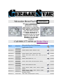
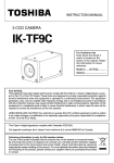
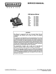
Mercedes Benz Fuel Distributors
We carry a complete line of
remanufactured fuel
distributors, covering
applications for all Mercedes
Benz vehicles, including both
U.S. and European versions.
Each Mercedes Benz fuel
distributor carries a full 12month warranty. A
refundable $100 core charge
applies to each unit. Fuel
distributors for all other
European cars are also
available.
Call 800-377-6598 or Order Here
Part #
0000740313
0000740413
0000740713
0000740813
0000740913
0000741013
0000741113
Bosch #
0438100012
0438100046
0438100068
0438100089
0438100041
0438100086
0438100054
0438100069
0438100011
0438100036
0438100084
0438100071
0438100091
0438100040
0438100085
0438100099
0438100106
0438100087
0438100088
0000741313
0438100111
0438100112
0000741413
0438101002
Mercedes Benz Fuel Distributor
Application Notes
Price
450SE, 450SEL, 450SL, 450SLC to 1979
$465.00
450SE, 450SEL, 450SL, 450SLC from 1980
$495.00
280CE, 280E, 280SE, 280SEL, 280SL, 280SLC (European
version)
$495.00
280CE, 280E, 280SE 1977 – 79
$465.00
230CE, 230E, 230GE, 230TE (European version)
$425.00
280CE, 280E, 280SE from 1980
$465.00
380SE, 308SEC, 380SEL, 380SL, 380SLC, 500SEC,
500SEL
380SE, 380SEC, 380SEL, 380SL, 380SLC, 500SE,
500SEC, 500SEL, 500SL
(European version)
190E, 230E, 230TE (European version)
$465.00
$495.00
$425.00
0000741513
0000741913
0000742013
0000742313
0000742413
0000742513
0000742713
0000742813
0438101003
0438101004
0438101011
0438101012
0438101025
0438101026
0438101027
0438101028
0438101017
0438101018
0438101015
0438101016
0438101009
0438101010
0438101043
0438101044
190E to 1986
$395.00
190E 2.6, 260E, 300E, 300SE, 300SEL, 300TE
$465.00
190E from 1987
$395.00
190E 16V
$495.00
420SEL, 560SEC, 560SEL, 560SL
$495.00
500SL to 1992
$495.00
190E 16V (European version)
$495.00
300CE, 300SL 1990 - 92
$465.00
German Star
Mercedes Benz Fuel Distributors
16232 N. Cerro Alto Dr.
Fountain Hills, AZ 85268
Toll Free: (800) 377-6598
Local Phone: (480) 836-4515
Fax: (480) 837-2886
Email: [email protected]
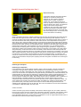
1993-95 Chrysler Concord, New Yorker, LHS, Dodge Intrepid
and Eagle Vision.
The K-Series fuel injection systems are continuous mechanical fuel injection
systems used on a wide variety of European vehicles, including such makes as
Volkswagon, Audi, BMW, Mercedes, Porsche, Volvo and Saab. The system is one
of the most common fuel injection systems on the market today, but also is one
of the least understood.
The K-Jetronic System constantly injects fuel into the engine as long as the car is
running and air flow is present to move the sensor plate in the airflow sensor. The
sensor plate is connected to an arm that pushes up on a plunger located in the
fuel distributor. As airflow changes, the movement of the sensor plate and the
plunger increase and decrease the volume of fuel injected into the engine. Since
fuel is being injected constantly, fuel pressure will have a direct affect on
driveability. As a matter of fact, fuel pressure is the single most critical element
when diagnosing driveability problems in the K-Series fuel injection systems. An
accurate fuel pressure gauge must be used when testing these systems, with a
range of 0 to more than 100 psi. You will also need a digital volt ohm meter
(DVOM) that can read milliamps.
You will work with three types of pressures when diagnosing these systems:
system pressure, control pressure (also known as counter pressure) and rest
pressure.
System pressure is the total fuel pressure produced by the fuel pump on a
constant basis. The fuel pump must be able to maintain this pressure during all
driving conditions from idle to wide open throttle. As a rule, system pressure will
run about 5 to 5.5 bar pressure, or 75 to 85 psi (1 bar = about 15 psi) and the
pump should be able to produce a minimum volume of 1 pint in 15 seconds.
When deadheaded, the K-Series fuel pump will produce about 1.5 times the
system pressure or about 110 to 120 psi. System pressure is a function of volume
of fluid moved against a restriction, so to maintain system pressure at the desired
level, there must be some type of restriction built into the fuel system. This
restriction is more commonly known as the fuel pressure regulator. The fuel
pressure regulator restricts the return of fuel to the tank by a calibrated amount,
maintaining system pressure at the desired level. On early K-Jet systems, this
regulator was a slide valve (also known as a push valve) internal to the fuel
distributor. Fuel pressure could be adjusted by adding or removing shims from
the valve. On later K-Jet systems, the regulator is the conventional diaphragm
type.
Control pressure (or counter pressure) is the pressure that is metered to the top
of the fuel plunger on a K-Jet system. By changing the counter pressure, the
resistance to plunger movement is changed, allowing enrichment and enleanment
of the fuel mixture to the engine. On a car equipped with K-Jet, this pressure is
controlled by the warm-up regulator.
The warm-up regulator only compensates for engine temperature and is therefore
a rather coarse control of fuel mixture. (Some K-Jet warm-up regulators also
have a vacuum port to help with the acceleration enrichment and deceleration
enleanment function.) Typical control pressures on a K-Jet warm-up regulator are
55 psi with the engine at full operating temperature and 20 to 30 psi on a cold
engine. (The colder the engine, the lower the pressure.)
A car equipped with K-Jet Lambda also changes control pressure with a warm-up
regulator (with pressures similar to a plain K-Jet system), but also controls lower
chamber pressure in the fuel distributor by bleeding pressure through a frequency
valve. By modifying lower chamber pressure, a change in volume of injected fuel
is made, enriching or enleaning the mixture. The frequency valve is nothing more
than an electrically duty-cycled fuel pressure regulator controlled by an on-board
computer in response to an oxygen sensor signal. This system provides a more
precise and rapid control of fuel mixture. Typical duty cycle on a properly running
engine is 45 percent to 55 percent duty and fluctuating. A quick test of this
system is to start the engine and test the frequency valve for vibration or noise -it should vibrate. Also, unplugging the oxygen sensor will put the system in open
loop and fix the frequency valve at a 50 percent duty cycle.
The KE-Jet system provides quicker response and more precise control of fuel
mixture than the K-Jet Lambda system and is the current K-Jet system in use.
This system uses a device called a differential pressure regulator to control fuel
mixture in response to both engine temperature and oxygen sensor signals. In
the KE-Jet system, counter pressure is broken down into primary counter
pressure and control counter pressure. Primary counter pressure is the pressure
applied to the top of the fuel plunger. This pressure stays constant and is the
same as system pressure.
Control counter pressure is modified by the differential pressure regulator and is
actually the lower chamber pressure in the fuel distributor. By modifying lower
chamber pressure, the fuel mixture can be enriched or enleaned in response to
temperature and oxygen sensor signals. Typical control counter pressures are 4
to 7 psi less than system pressure on a fully warmed engine and 17 to 20 psi less
than system pressure on a cold engine (typical system pressures are 5.0 to 5.5
bar or 75 to 85 psi). The signal to the differential pressure regulator from the
computer is measured in milliamps of current. To test this signal, a DVOM must
be placed in series with the differential pressure regulator. Typical current values
are 80 milliamps cold engine (15k ohm resistor in place of coolant temp sensor to
simulate a cold engine condition); 120 milliamps during cranking (this is a crank
enrich function to aid starting); and 8 to 12 milliamps warm idle. (Note: always
check service manual for values.) These values correspond to the fuel pressures
listed. In other words, at 80 milliamps current you should show 17 to 20 psi less
than system pressure.
Rest pressure is the fuel pressure maintained in the system by the fuel
accumulator after engine shutdown. The fuel accumulator is a large spring-loaded
diaphragm that maintains a pressure of about 1.5 to 2.0 bar for 30 minutes or
more after engine shutdown. This rest pressure provides for fast restart and
prevents fuel percolation or boiling (vapor lock). Always check the service manual
for the car line you are working on for proper rest pressures and times. Typical
symptoms caused by accumulator problems are extended crank time and hard
start hot.
With an understanding of the system and the proper tools, K-Jetronic fuel system
service is a straightforward procedure that can keep your service bays full all year
long. Give me a call if you have any questions!
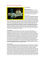
C. Diagnosing Bosch KE-Jetronic Injection
If you've done much work on European cars, you've encountered Robert Bosch KJetronic mechanical fuel injection, which first appeared in the early seventies. It's an
efficient, multi-port, continuous (the "K" stands for that word auf Deutsch) spray
system that works so well it allowed some car makers to avoid adding catalytic
converters for a few years after everybody else needed them to comply with emissions
regulations. Yet, it's less expensive than regular electronic port injection, better than
TBI (Throttle Body Injection) because it doesn't allow stratification of the blend in the
manifold, and relatively simple -- that is, once you understand it.
Mechanical, but electronic, too
As with just about everything else automotive, K-Jet didn't escaped change in the last
decade. When three-way catalysis became necessary in order to meet NOx limits, a
means of keeping the air/fuel mix closer to the ideal stoichiometric ratio (that is,
14.7:1 air to fuel by weight) than could possibly be achieved mechanically was
needed. So, this injection set-up got add-on electronics to give closed-loop operation
and satisfy the Feds. First, this was called K-Jetronic with Lambda (that Greek letter
has come to represent the stoichiometric blend), but later came a more elegantly
simple version, KE-Jetronic. You'll find it on several Volkswagen and Audi models
from '84 up, even the entry-level Fox (a neat little car that, in our opinion, outclassed
its competition).
Since VW has made more vehicles with this system (which the company calls CIS-E
for "Continuous Injection System-Electronic) than everybody else put together, I'll
give you the gospel according to Wolfsburg and use the Fox as my example.
Although I'm being very model-specific here, a lot of what I say will give you a better
understanding of K-Jetronic in general.
Flow
The little Volks has a fuel supply system with a small in-tank transfer pump that sends
gasoline up to a reservoir. From there, the main roller-cell electric pump (which
should never be allowed to run dry) picks it up and pushes it into an accumulator,
which protects the metal diaphragm in the fuel distributor from the shock of the pump
turning on, and maintains residual pressure after the engine is shut down to help avoid
vapor lock.
After passing though a big, lifetime filter mounted on the same bracket as the pump
and accumulator, the flow reaches the fuel distributor, and here's where you'll find the
main differences between KE and other CIS's. As you know if you read the previous
section, the basic principle of Bosch continuous injection is that a metal disc floating
in a cone moves in accordance with the amount of air entering the engine, and the
disc's lever is connected to a control plunger that rises in a barrel progressively
uncovering fuel-metering slits. The more air being taken in, the more the disc moves,
and the more gasoline is delivered. This much remains the same.
Mixmaster
Differential pressure valves still serve to maintain the pressure drop at the metering
slits regardless of how much fuel is flowing through them, and here's where KE's
closed-loop mix control comes in. An electro-magnetic differential pressure regulator
(a small plastic box screwed to the side of the fuel distributor -- its presence will let
you know the system is KE) opens and closes as commanded by the ECU, varying
pressure in the lower chamber of the fuel distributor. When the computer gets a lean
signal from the oxygen sensor, it sends additional current to the pressure regulator,
increasing differential pressure, hence fuel flow, so the blend richens. And vice versa.
Although the whole differential pressure versus fuel flow concept is a little hard to
grasp, what I've just said is really all you need to know for diagnosis.
The injectors themselves, by the way, are of the air-shrouded variety that provide a
very finely atomized spray. Air flow through passages in the cylinder head really
breaks up those droplets.
Instead of the combo of a control pressure regulator and a pressure relief valve, KEJet has only a diaphragm-type pressure regulator, which maintains about 78 psi in the
system by venting the excess back to the tank, and also keeps residual pressure
available after the engine's shut down.
A cold start valve sprays extra gas into the intake manifold when it gets voltage from
the thermo-time switch, just like previous systems. Also similar is the auxiliary air
regulator, which is plumbed across the throttle plate to let in extra air for fast idle.
With that operational explanation taken care of, I'll look at service. As with every
other modern engine control or fuel injection system, don't assume a driveability or
performance problem is due to KE-Jet until you've checked for ignition problems,
vacuum leaks, poor compression, etc. If it's not tampered with, this set-up should stay
in calibration and last just about forever. But that's not to say you'll never run into any
problems with it.
Closed loop?
The first thing to find out is if the closed-loop mode is ever being entered, and for that
you'll need a milli-amp meter and either a special VW wiring adapter (I'd be surprised
if you bought such a thing) or some home-made leads. With the ignition off, unplug
the two-terminal connector from the differential pressure regulator. Those Bosch
plugs can be difficult if you're not used to them -- pry off the metal clip completely
with a small screwdriver, then separate the connection. Using very narrow spade
terminals, crimp a male to one end of a six-inch wire, and a female to the other.
Attach a similar pair of spades to the leads of your meter (I found that an ordinary
analog multi-meter worked fine). Since a short here can blow the electronics, I
wrapped the spades with electrical tape to make sure they wouldn't make contact with
each other.
Now, connect the male end of your jumper to one side of the plug, the female end to
the corresponding spade of the differential pressure regulator, then attach your meter
in series across the other terminals, and set it to the milli-amp scale. Start the engine,
let it get warm, and make sure all electrical accessories are off. Once normal operating
temp is reached (remember, any oxygen sensor has to be warm to work, so you may
need to hold rpm at 2,500 or so for a while to heat it up) look for a reading of 10 mA
+ or - 6, and it should fluctuate over a 1-3 milli-amp range. That fluctuation is the tipoff that closed-loop operation is occurring -- in open loop, the ECU sends a fixed
10mA signal, which won't cause any drivability problems, but will increase
emissions.
A CO test should ideally go along with this. If you happen to access to an exhaust
analyzer, pick up the sample at the convenient tube you'll find in front of the manifold
(it has a blue rubber cap), make sure the timing is at 6 degrees BTDC and the idle
speed is 900 rpm, then look for 0.3% to 1.2%. Altering the mixture requires drilling
out a plug between the air sensor and the fuel distributor, then inserting a long metric
allen wrench, but normally there'll be no reason to fool with this.
Garbage in . . .
If the computer isn't sending a proper signal to the differential pressure regulator,
check the inputs. First, the coolant temperature sensor, which is of the NTC (Negative
Temperature Coefficient) type that loses resistance as it gets hot. At 32 degrees F.,
there should be 6K ohms across its terminals, at 68 degrees 2.5K ohms, and at 176
degrees a mere 300 ohms. Next, measure oxygen sensor voltage, which should range
between about 1/10 and one volt.
A good, straightforward test is to unplug the temperature sensor connector and bridge
its leads with a jumper (no resistance, so the computer will think the engine's warmed
up), then separate the oxygen sensor lead from the green wire, and observe the milliamp reading at the differential pressure regulator as before. You should get 9-11 mA.
Now, ground the green wire. Within 20 seconds, expect the meter to show 19-22 mA.
No? Then check the wiring from the ECU to the oxygen sensor. If that's okay, the
computer's probably bad, which is an unusual, but expensive, occurrence.
A complete lack of current to the differential pressure regulator won't make the car
undriveable, but there may be a little roughness because the mixture will be lean. My
VW Service Training contact warned me about a common cause of this electrical
failure: "The 10 amp system fuse is auxiliary, mounted on the outside of the fuse and
relay panel," he said. "People think it's a spare fuse and take it out to use it elsewhere.
I've fixed cars that have been worked on for days simply by installing a fuse."
Won't hold
Hot restarting trouble can usually be traced to a loss of residual pressure in the
injector lines that promotes percolation -- you'll have to crank for quite a while to
purge all those bubbles. To check, attach a pressure gauge to the fuel line that goes to
the cold start valve, run the engine, shut it off, and watch the needle. If it doesn't hold
at about 38 psi for at least 10 minutes, the check valve in the pressure regulator is
probably leaking.
The KE-Jet control plunger inside the fuel distributor seats on an O-ring, so a small
amount of clearance between the air sensor lever and the plunger (engine off) is
required or residual pressure will be lost. If you're used to other CIS's and you notice
this clearance, you may jump to the unfortunate conclusion that the sensor plate is out
of adjustment and get yourself in trouble. That little bit of free-play is supposed to be
there. To see if it is, make sure there's pressure in the system (you can run the fuel
pump by removing the pump's electrical relay and bridging panel terminals #30 and
#87 for about five seconds), then try to lift the sensor plate using a magnet on its 10
mm center bolt. You should feel somewhere between just noticeable clearance and
.080 in. (that's 5/64 in., or 2mm) of movement. While you're there, you might as well
raise the plate through its full range to find out if it's binding, which condition can be
corrected by loosening the bolt, centering the plate so a .004 in. feeler gauge can go
all the way around it, and retightening the bolt (four ft. lbs. will do, and thread locking
compound is a good idea here).
Coping with cold
When you encounter a hard- or no-start-while-cold problem, think about the thermotime switch and the cold start valve. The points in the switch open at 86 degrees F., so
make sure the engine's below that temperature, then remove the connector from the
cold start valve, ground terminal #4 of the ignition coil, and put a test light across the
connector's terminals. Run the starter and the light should glow for between one and
eight seconds, then wink out.
To test the fuel delivery of the valve itself, remove the two Allen head screws that
hold it to the intake manifold, detach the valve and aim its business end into a suitable
container, energize the fuel pump as explained above, then connect a jumper from the
positive battery post to one of the valve's terminals, and another jumper to ground (be
careful not to make any sparks!). You should see a steady cone-shaped spray pattern.
Disconnect the wires and no drops should appear at the valve tip for at least a minute.
If the powerplant tends to stall when cold because there's no fast idle, examine the
auxiliary air regulator. With the coolant below 80 degrees F., unplug the regulator's
electrical connector, start the engine and let it idle. Pinch either hose that's routed to
the regulator and idle speed should decrease slightly. Let the engine reach normal
operating temperature, plug the connector back in, and pinch again. You should hear
no change in rpm. In cases where fast idle never kicks out, see that current is reaching
the heating element in the regulator (that's what warms the bimetal and shuts off the
flow of air) by using a test light across the connector terminals with the key on. No
light means there's an open somewhere between the fuel pump relay and the plug.