1
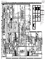
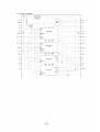
6-4. SCHEMATIC DIAGRAM
r
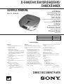
D- E440/E441/E441SR/E443/
E445/E446CK/E449CK
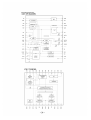
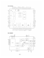
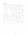
Refer to page 24 for IC Block Diagrams.
r Waveforms
1
SERVICE MODE
during TRK servo OFF
2
3
136 µsec
4.2 MHz
IC502 &ª
IC502 #§
VOLT/DIV : 1 V AC
TIME/DIV : 0.1 msec
IC502 &º
7
– 20 –
– 21 –
VOLT/DIV : 1 V AC
TIME/DIV : 10 msec
6
0.9 Vp-p
0.2 Vp-p
16.9 MHz
VOLT/DIV : 1 V AC
TIME/DIV : 0.2 msec
0.8–1.2 Vp-p
– 19 –
ESP : OFF
4.19MHz
ESP : OFF
PLAY MODE
IC501 @£
IC502 ^•
VOLT/DIV : 1 V AC
TIME/DIV : 50 µsec
2.6 Vp-p
0.47 µsec
22.7 µsec
ESP : OFF
5
4
2.6 Vp-p
2.6 Vp-p
2.4 Vp-p
IC301 !§
VOLT/DIV : 0.1 V AC
TIME/DIV : 50 nsec
IC801 @º
VOLT/DIV : 0.2 V AC
TIME/DIV : 0.1 µsec
Note:
• All capacitors are in µF unless otherwise noted. pF: µµF
50 WV or less are not indicated except for electrolytics
and tantalums.
• All resistors are in Ω and 1/4 W or less unless otherwise
specified.
¢
•
: internal component.
Note:
Note:
The components identi- Les composants identifiés
fied by mark ! or dotted par une marque ! sont criline with mark ! are cri- tiques pour la sécurité.
tical for safety.
Ne les remplacer que par
Replace only with part
une piéce portant le
number specified.
numéro spécifié.
• U : B+ Line.
• H : adjustment for repair.
• Power voltage is dc 4.5 V and fed with regulated dc power
supply from external power voltage jack. (J401)
• Voltages and waveforms are dc with respect to ground
under no-signal conditions.
• Voltages and current are taken with a VOM (Input impedance 10 MΩ).
Voltage variations may be noted due to normal production tolerances.
• Waveforms are taken with a oscilloscope.
Voltage variations may be noted due to normal production tolerances.
• Circled numbers refer to waveforms.
• Signal path.
J : CD
VOLT/DIV : 0.2 V AC
TIME/DIV : 0.5 msec
– 22 –
– 23 –