1
Ohaus Corporation
19A Chapin Road
P.O. Box 2033
Pine Brook, NJ 07058-2033 USA
www.ohaus.com
RANGER
COUNTING & WEIGHING SCALES
SERVICE MANUAL
Ohaus Corporation 19A Chapin Road, P.O. Box 2033, Pine Brook, NJ 07058-2033 (973) 377-9000
Ohaus Corporation
SERVICE MANUAL
Ranger Counting and Weighing Scales
Rang
Cle
ar
APW
S
Selcale
ect
C
Weiount
ght
er
Cou
nt
Sam
10 ple
Sam
Sizeple
Counting Scale
Rang
er
Weighing Scale
The information contained in this manual is believed to be accurate at the time of publication, but
Ohaus Corporation assumes no liability arising from the use or misuse of this material. Reproduction of this material is strictly prohibited.
Material in this manual is subject to change.
© Copyright 2001 Ohaus Corporation, all rights reserved.
® Registered trademark of Ohaus Corporation.
TABLE OF CONTENTS
CHAPTER 1 INTRODUCTION
Page
Overview of Ranger Counting Scale Controls ........................................ 1-1
Overview of Ranger Weighing Scale Controls ........................................ 1-3
Introduction .......................................................................................... 1-4
Service Facilities .................................................................................... 1-4
Tools and Test Equipment Required ...................................................... 1-5
1.5.1 Special Tools .................................................................................. 1-5
1.5.2 Standard Tools and Test Equipment .............................................. 1-5
1.6 Test Masses Required ............................................................................ 1-5
1.7 Specifications ......................................................................................... 1-6
1.1
1.2
1.3
1.4
1.5
CHAPTER 2 TROUBLESHOOTING
2.1 Troubleshooting ...................................................................................... 2-1
2.2 Diagnostic Guide (Table) ........................................................................ 2-1
2.2.1 Diagnosis ........................................................................................ 2-1
2.3 Error Codes .......................................................................................... 2-3
2.4 Error Messages After Service Work ........................................................ 2-3
CHAPTER 3 MAINTENANCE PROCEDURES
3.1 Preventive Maintenance ......................................................................... 3-1
3.1.1 Preventive Maintenance Checklist.................................................. 3-1
3.2 Testing.
.......................................................................................... 3-1
3.2.1 Operational Test ............................................................................. 3-1
3.2.1.1 Segment Display Test ....................................................... 3-1
3.2.2 Menu Structure................................................................................ 3-2
3.2.3 Ranger Counting Switch Functions ................................................ 3-6
3.2.4 Ranger Counting Scale Menu Operation ........................................ 3-7
3.2.4.1 How to Enter the Menus .................................................... 3-7
3.2.4.2 How to Select a Specific Menu .......................................... 3-7
3.2.4.3 How to Enter an Individual Menu ....................................... 3-7
3.2.4.4 How to Enter an Individual Menu Item ............................... 3-8
3.2.4.5 How to Save and Store an Individual Menu Item ............... 3-8
3.2.4.6 How to Quit the Menus ...................................................... 3-8
3.2.4.7 Calibration Menu ............................................................... 3-8
3.2.4.8 Setup Menu ....................................................................... 3-9
3.2.4.9 Read Menu ...................................................................... 3-10
3.2.4.10 RS232-1/RS232-2 Menus ............................................... 3-11
3.2.4.11 Lockout Menu .................................................................. 3-13
3.2.4.12 Quit menu ........................................................................ 3-14
3.2.5 Ranger Weighing Scale Switch Functions ................................... 3-14
3.2.6 Ranger Weighing Scale Menu Functions ..................................... 3-14
3.2.6.1 How to Enter the Menus .................................................. 3-14
3.2.6.2 How to Select a Specific Menu ........................................ 3-14
3.2.6.3 How to Enter an Individual Menu ..................................... 3-15
3.2.6.4 How to Enter an Individual Menu Item ............................. 3-15
i
TABLE OF CONTENTS (Cont.)
3.2.6.5 How to Save and Store an Individual Menu Item ............. 3-15
3.2.6.6 How to Quit the Menus .................................................... 3-15
3.2.6.7 Calibration Menu ............................................................. 3-15
3.2.6.8 Setup Menu ..................................................................... 3-16
3.2.6.9 Read Menu ...................................................................... 3-17
3.2.6.10 RS232-1/RS232-2 Menus ............................................... 3-18
3.2.6.11 Lockout Menu .................................................................. 3-19
3.2.6.12 Quit Menu ........................................................................ 3-20
3.2.7 Calibration and Sealing ................................................................ 3-21
3.2.7.1 Calibration Masses .......................................................... 3-21
3.2.7.2 Calibration Procedure ..................................................... 3-21
3.2.7.3 Unlocking the Menus ....................................................... 3-22
3.2.7.4 Weights and Measures Sealing ....................................... 3-23
3.2.8 Performance Tests ........................................................................ 3-24
3.2.8.1 Repeatability Test ........................................................... 3-24
3.2.8.2 Off-Center Load Test ....................................................... 3-25
3.2.8.3 Linearity Test ................................................................... 3-25
3.2.9 RS232 Interface Test .................................................................... 3-27
3.2.9.1 Connecting the RS232 Interface ..................................... 3-27
3.2.10 Print Test ...................................................................................... 3-28
3.2.11 Visual Inspection .......................................................................... 3-28
3.3 Repair Procedures ................................................................................ 3-29
3.3.1 Replacing the Keypad Membrane ................................................ 3-29
3.3.2 Replacing the AC Adapter ............................................................ 3-29
3.3.3 Replacing the Internal Rechargeable battery ................................ 3-30
3.3.4 Replacing the Analog PCB ........................................................... 3-32
3.3.5 Replacing the Display Mounting Plate, Display Unit
and Digital PCB ............................................................................ 3-32
3.3.5.1 Preliminary Work ............................................................. 3-32
3.3.5.2 Replacing the Display Mounting Plate ............................ 3-33
3.3.5.3 Replacing the Liquid Crystal Display (LCD)
or the Backlighting Unit ................................................... 3-33
3.3.5.4 Replacing the Digital PCB .............................................. 3-33
3.3.6 Final Reassembly ......................................................................... 3-34
3.3.7 Replacing the Software................................................................. 3-34
3.3.8 Replacing the Weighing Cell ........................................................ 3-34
3.3.8.1 Replacing a Strain Gauge Weighing Cell........................ 3-34
3.3.9 Accessing and Using Service Mode ............................................. 3-36
3.3.9.1 Accessing Service Mode with Scales that are not Certified ..... 3-36
3.3.9.2 Accessing Service Mode with Certified Scales ............... 3-36
3.3.9.3 Accessing Service Mode ................................................. 3-37
3.3.9.4 Service Mode Blocks ....................................................... 3-37
3.3.9.5 Working in Service Mode ................................................ 3-38
ii
TABLE OF CONTENTS (Cont.)
CHAPTER 4 DATA TABLES
4.1 introduction .......................................................................................... 4-1
4.1.1 Certifiable and Certified Ranger Scales with Strain Guage
Weighing Cells ............................................................................... 4-1
4.1.2 Noncertifiable Ranger Scales with Strain Guage Weighing Cells .. 4-2
4.1.3 Overview of Weighing Cells and Preloads ..................................... 4-3
4.1.4 Geographical Adjustment Values ................................................... 4-4
CHAPTER 5 DRAWINGS AND PARTS LISTS
5.1 Drawings....... .......................................................................................... 5-1
5.2 Miscellaneous Parts.............................................................................. 5-14
iii
TABLE OF CONTENTS (Cont.)
LIST OF TABLES
TABLE NO.
1-1
1-2
1-3
1-4
1-5
1-6
2-1
2-2
3-1
3-2
3-3
4-1
4-2
4-3
4-4
TITLE
PAGE NO.
Ranger Calibration Masses kg .......................................................... 1-5
Ranger Calibration Masses lb ........................................................... 1-5
Ranger Count NTEP Version Specifications ..................................... 1-6
Ranger Weighing NTEP Version Specifications ............................... 1-7
Ranger Count OIML Specifications ................................................... 1-8
Ranger Weighing OIML Version Specifications................................. 1-8
Diagnostic Guide ............................................................................... 2-2
Error Codes ....................................................................................... 2-3
Types of Performance Tests ............................................................ 3-24
Linearity Test Masses ...................................................................... 3-25
RS232 Commands .......................................................................... 3-28
Data for Certifiable/Certified Ranger Scales ...................................... 4-1
Data for Noncertifiable Ranger Scales .............................................. 4-2
Strain Gauge Weighing Cells ............................................................ 4-3
Ranger Geographical Adjustment Values ......................................... 4-4
LIST OF ILLUSTRATIONS
FIGURE NO.
3-1
3-2
3-3
3-4
3-5
3-6
3-7
5-1
5-2
5-3
5-4
5-5
5-6
5-7
5-8
5-9
5-10
TITLE
PAGE NO.
Segment Displays ............................................................................. 3-1
Ranger Counting Scale Menus ......................................................... 3-2
Ranger Weighing Scale Menus ......................................................... 3-4
Ranger Service Menu Structure ........................................................ 3-6
Off-Center Load Test Mass Locations.............................................. 3-25
RS232 Interface Pin Connections ................................................... 3-27
Unlock Switch Locations ................................................................. 3-34
Top Components, High Capacity Scale (Strain Gauge) Shown ........ 5-3
Switch Actuators, High Capacity Scale (Strain Gauge) Shown ......... 5-4
Bottom Components, High Capacity Scale (Strain Gauge) Shown ... 5-5
Power Pack, High Capacity Scale Shown ......................................... 5-7
Weigh Display ................................................................................... 5-8
Count Display .................................................................................... 5-8
Top Components, Low Capacity Scale (Strain Gauge) Shown ......... 5-9
Switch Actuators, Low Capacity Scale Shown ................................ 5-10
Bottom Components, Low Capacity Scale (Strain Gauge) Shown .. 5-11
Power Pack, Low Capacity Scale Shown ....................................... 5-13
iv
CHAPTER 1 INTRODUCTION
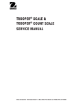
1.1 OVERVIEW OF RANGER COUNTING SCALE CONTROLS
5
6
4
3
2
1
Rang
Cle
ar
APW
S
Selcale
ect
C
Weiount
ght
er
Cou
nt
Sam
10 pl
e
Sam
Sizeple
7
9
10b
8
Rear of scale
10a
11 12 13 14
15
Display
16
17
18
12 12
Com
tbz NET B/G
24
kg %Pcs
Auto Opt
%0
100
50
23
Function keys
22
Clear
APW
Scale
Select
Count
Weight
Sample
10
Sample
Size
25
26
27
28
29
30
1-1
19
20
21
CHAPTER 1 INTRODUCTION
1.1 OVERVIEW OF RANGER COUNTING SCALE CONTROLS (Cont.)
Scale
18 Weighing range display (for dual range
1
Keypad
2
Function keys
19 Symbols for net/gross weight
3
Display
20 Battery discharge status (optional battery)
4
Scale specifications
21 Weighing unit
5
Weighing pan
22 Number of user selected reference pieces
6
Power cord
23 Weighing range bar graph
7
Power cord with AC Adapter (Scale with
24 Center of zero indicator
scales)
internal battery optional)
8
Function keys
Adjustable feet
25 Clear APW and return to weighing.
Rear of scale
9
26 Average Piece Weight - one piece refer-
Jack for AC Adapter (battery option)
ence weight is displayed for 3 seconds.
10a Serial # label (Europe)
27 If RS is set to reference or bulk mode, this
10b Serial # label (USA) under weighing plat-
button switches the display between the
form
host scale and the remote scale. Tare, Zero
11 Hole for antitheft device
and G/N/T buttons functions are active for
12 Spirt level
the scale being displayed.
13 RS232 Interface (Optional)
28 Switch between Weighing and Counting
14 RS232 Interface (Standard)
Modes.
29 Used for a sample size of 10 pieces.
Display
30 Continuous press - scrolls through 5, 15,
15 Stability indicator
20, 25, 30, 50 and 100 pieces - sample size.
16 Active interface (for menu mode)
Short press - take sample size as indicated
17 Active scale (in 2-scale systems)
1-2
CHAPTER 1 INTRODUCTION
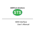
1.2 OVERVIEW OF RANGER WEIGHING SCALE CONTROLS
4
5
3
2
1
Rang
er
6
9b
7
8
Rear of scale
9a
10 11 12 13
15
14
Com 12
tbz NET
Display
kg Pcs
16
1
2
3
4
5
6
7
8
9a
9b
Keypad
Display
Capacity label
Weighing pan
Power cord
AC Adapter (Scale with battery option)
Adjustable feet
Jack for AC Adapter (battery option)
Serial # label (Europe)
Serial # Label (USA) under weighing
platform
17 18
10
11
12
13
14
15
16
17
18
19
1-3
1
19
Hole for antitheft device
Spirt level
RS232 Interface (Optional)
RS232 Interface (Standard)
Stability indicator
Weighing range display (for dual range
scales)
Center of zero indicator
weighing unit
Net symbol when weighing with tare
Battery discharge status (optional)
CHAPTER 1 INTRODUCTION
1.3 INTRODUCTION
This service manual contains instructions for the repair and maintenance work to be performed by
service engineers on the Ranger Counting and Weighing Scales (Strain Gauge loadcells). It is
assumed that the reader is familiar with the operation of the Scale and can refer to the relevant
operating instructions when necessary.
This manual covers maintenance on the following:
Ranger Counting Scales (small platform, capacities 3kg and 6kg)
Ranger Counting Scales (large platform, capacities 12kg (NTEP), 15kg (OIML), 30kg,
35kg and 60kg)
Ranger Weighing Scales (small platform, capacities 3kg and 6kg)
Ranger Weighing Scales (large platform, capacities 12kg (NTEP), 15kg (OIML),
30kg (NTEP), 35kg (OIML) and 60kg.
The contents of this manual is contained in five chapters.
Chapter 1 Introduction - Contains information regarding service facilities, tools and test equipment,
test masses, and specifications.
Chapter 2 Troubleshooting - Contains a diagnosis/diagnostics chart and error code table.
Chapter 3 Maintenance Procedures - Contains preventive maintenance procedures, performance
tests and adjustments, repair procedures, service mode procedures, and calibration procedures.
Chapter 4 Drawings and Parts Lists - Contains exploded views of Ranger Scales identifying all
serviceable replacement components with parts lists.
Before servicing the scale, you should be familiar with the Instruction Manual which is packed with
every Ranger Scale.
1.4 SERVICE FACILITIES
To service the Ohaus Ranger Scale, the service area should meet the following requirements:
DO NOT SERVICE the scale:
• Next to open windows or doors causing drafts or rapid temperature changes.
• Near air conditioning or heat vents.
• Near vibrating, rotating or reciprocating equipment.
• Near magnetic fields or equipment that generates magnetic fields.
• On an unlevel work surface.
• Allow sufficient space around the instrument for ease of operation and keep away from radiating
heat sources.
1-4
CHAPTER 1 INTRODUCTION
1.5 TOOLS AND TEST EQUIPMENT REQUIRED
In order to properly service the Ohaus Ranger Scales, a standard electronic tool kit is required. No
special tools and test items are required.
1.5.1 Special Tools
None required.
1.5.2 Standard Tools and Test Equipment
1. Digital Voltmeter (DVM) - Input impedance of at least 10 megohms in the 1 Volt dc position.
2. Torx screwdrivers, TX8, TX20, TX30 and TX50
1.6 TEST MASSES REQUIRED
The masses required to test the Ohaus Ranger Scales must meet the requirements of ASTM
Class 4 Tolerance. The mass values are listed in Tables 1-1 and 1-2.
TABLE 1-1. RANGER CALIBRATION MASSES KG
TYPE
Weighing SG
Weighing SG
Weighing SG
Weighing SG
Weighing SG
Weighing SG
Weighing SG
MODEL
RD3RS
RD6RS
RD12LS
RD12LS
RD30LS
RD30LS
RD60LS
CAPACITY
3kg
6kg
12kg
15kg
30kg
35kg
60kg
SPAN
3kg
6kg
12kg
15kg
30kg
35kg
60kg
LINEARITY
1.5kg
3kg
6kg
7.5kg
15kg
17.5kg
30kg
NOTES
Single Range (NTEP)
Dual Range (OIML)
Single Range (NTEP)
Dual Range (OIML)
Single Range (NTEP)
TABLE 1-2. RANGER CALIBRATION MASSES LB
TYPE
Weighing SG
Weighing SG
Weighing SG
Weighing SG
Weighing SG
Weighing SG
Weighing SG
MODEL
RD3RS
RD6RS
RD12LS
RD12LS
RD30LS
RD30LS
RD60LS
CAPACITY
6lb
12lb
24lb
30lb
60lb
70lb
120lb
SPAN
6lb
12lb
24lb
30lb
60lb
70lb
120lb
1-5
LINEARITY
3lb
6lb
12lb
7.5lb
30lb
35lb
60lb
NOTES
Single Range (NTEP)
Dual Range (OIML)
Single Range (NTEP)
Dual Range (OIML)
Single Range (NTEP)
CHAPTER 1 INTRODUCTION
1.7 SPECIFICATIONS
Complete specificatons for the Ohaus Ranger Counting and Weighing Scales are listed in Tables
1-3 through 1-6. When a scale has been serviced, it must meet the specifications listed in the table.
Before servicing the scale, determine what specifications are not met.
TABLE 1-3. RANGER COUNT NTEP VERSION SPECIFICATIONS
Standard Models NTEP*
RD3RS
RD6RS
Default Capacity x Readability (lb)
6 x 0.0005
12 x 0.001
Default Capacity x Readability(kg)
3 x 0.0002
6 x 0.0005
Default Capacity x Readability (g)
3000 x 0.2
6000 x 0.5
Default Capacity x Readability (oz)
60 x 0.005
120 x 0.01
RD12LS
RD30LS
RD60LS
24 x 0.002
60 x 0.005
120 x 0.01
12 x 0.001
30 x 0.002
60 x 0.005
12000 x 1
30000x 2
60000 x 5
240 x 0.02
600 x 0.05
1200 x 0.1
NTEP Capacity x Readability (lb)
6 x 0.001
12 x 0.002
24 x 0.005
60 x 0.01
120 x 0.02
NTEP Capacity x Readability (kg)
3 x 0.0005
6 x 0.001
12 x 0.002
30 x 0.005
60 x 0.01
NTEP Capacity x Readability(g)
3000 x 0.5
6000 x 1
12000 x 2
30000 x 5
60000 x 10
120 x 0.02
240 x 0.05
600 x 0.1
1200 x 0.2
NTEP Capacity x Readability (oz)
Linearity (g)
Order number:
Note NTEP for weighing only
Platform size (w x d) (in/cm)
60 x 0.01
+/- 0.2
RD3RS-2E0
+/- 0.5
+/- 1.0
+/- 2.0
RD6RS-2E0
RD12LS-2E0
RD30LS-2E0
................
General Specifications All Models
9.5 x 8 / 24 x 20
14 x 9.5 / 35 x 24
Scale dimensions (w x d x h) (in/cm)
10.5 x 13.2 x 4 / 26.5 x 33.5 x 10
Shipping dimensions (w x d x h) (in/cm)
16.5 x 19 x 10 / 42 x 48 x 25
Weight lb/kg)
11.5 / net
14.2 x 14.6 x 4.5 / 36 x 37 x 11.5
20 x 20.5 x 10.5 / 52 x 53 x 27
(14 / 6.5 gross)
21 / 9.5 net
Weighing units
(24 / 11 gross)
g, kg, lb, oz
Display
0.63 inch / 16 mm digit height, (Backlit LCD)
Power
Internal power supply / 40 hour rechargeable battery powered models available
Span Calibration
25% - 100% capacity
Linearity Calibration ( 3 point calibration)
0 – 50% - 100% capacity
Auto Zero Tracking
Construction
0.5d, 1d, 3d, OFF
Stainless steel weighing pan / Painted cast-aluminum housing
Protection
Operating temperature
IP43
Standard models -10°C to 40C°
Storage temperature
-20°C to 60°C
NOTE: Parts counting is not NTEP approvable.
1-6
+/- 5.0
RD60LS-2E0
CHAPTER 1 INTRODUCTION
1.7 SPECIFICATIONS (Cont.)
TABLE 1-4. RANGER WEIGHING NTEP VERSION SPECIFICATIONS
Standard Models NTEP
RD3RS
RD6RS
RD12LS
RD30LS
RD60LS
Default Capacity x Readability (lb)
6 x 0.0005
12 x 0.001
24 x 0.002
60 x 0.005
120 x 0.01
Default Capacity x Readability (kg)
3 x 0.0002
6 x 0.0005
12 x 0.001
30 x 0.002
60 x 0.005
Default Capacity x Readability (g)
3000 x 0.2
6000 x 0.5
12000 x 1
30000 x 2
60000 x 5
Default Capacity x Readability (oz)
60 x 0.005
120 x 0.01
240 x 0.02
600 x 0.05
1200 x 0.1
120 x 0.02
NTEP Capacity x Readability (lb)
6 x 0.001
12 x 0.002
24 x 0.005
60 x 0.01
NTEP Capacity x Readability (kg)
3 x 0.0005
6 x 0.001
12 x 0.002
30 x 0.005
60 x 0.01
NTEP Capacity x Readability (g)
3000 x 0.5
6000 x 1
12000 x 2
30000 x 5
60000 x 10
NTEP Capacity x Readability (oz)
60 x 0.01
120 x 0.02
240 x 0.05
600 x 0.1
1200 x 0.2
Linearity (g)
+/- 0.2
Order number:
RD3RS-2E0
+/- 0.5
+/- 1.0
+/- 2.0
RD6RS-2E0
RD12LS-2E0
RD30LS-2E0
+/- 5.0
RD60LS-2E0
Ranger Options
1
BATTERY
To order Ranger with internal rechargeable battery, add /1 to the order number above.
2
2nd RS232
To order Ranger with second RS232 data interface, add /2 to the order number above.
3
BATTERY &
2nd RS232
To order Ranger with both an internal rechargeable battery and second RS232 data interface, add /3 to the order
number above.
General Specifications
Platform size (w x d) (in/cm)
Scale dimensions (w x d x h) (in/cm)
9.5 x 8 / 24 x 20
14 x 9.5 / 35 x 24
10.5 x 13.2 x 4 / 26.5 x 33.5 x 10
Shipping dimensions (w x d x h) (in/cm)
16.5 x 19 x 10 / 42 x 48 x 25
Weight (lb/kg)
11.5 / net
(14 / 6.5 gross)
21 / 9.5 net
Weighing units
Display
Power
Span Calibration
Linearity Calibration ( 3 point calibration)
Auto Zero Tracking
Construction
Storage temperature
(24 / 11 gross)
g, kg, lb, oz
0.63 inch / 16 mm digit height, (Backlit LCD)
Internal power supply / 40 hour rechargeable battery powered models available
25% - 100% capacity
0 – 50% - 100% capacity
0.5d, 1d, 3d, OFF
Stainless steel weighing pan / Painted cast-aluminum housing
Protection
Operating temperature
14.2 x 14.6 x 4.5 / 36 x 37 x 11.5
20 x 20.5 x 10.5 / 52 x 53 x 27
IP43
Standard models -10°C to 40C°
-20°C to 60°C
1-7
CHAPTER 1 INTRODUCTION
1.7 SPECIFICATIONS (Cont.)
TABLE 1-5. RANGER COUNT OIML VERSION SPECIFICATIONS
Models
3 kg
WEIGHING RANGE
6 kg
15 kg
35 kg
Range 1
Range 2
Range 1
Range 2
Range 1
Range 2
Range 1
Default Cap. x Readability (kg)
1.5kg x0.5g
3kg x 1g
3kg x 1g
6kg x 2g
6 x 0.002
15 x 0.005
Default Cap. x Readability (g)
1500 x 0.5
3000 x 1
3000 x 1
6000 x 2
6000 x 2
Default Cap. x Readability (lb)
3 x 0.001
6 x 0.002
6 x 0.002
12 x 0.005
Default Cap. x Readability (oz)
30 x 0.02
60 x 0.02
60 x 0.02
120 x 0.05
General Specifications
Small Platform
Platform size (w x d) (cm)
24 x 20
Scale dimensions (w x d x h) (cm)
Range 1
Range 2
15 x 0.005
35 x 0.01
30 x 0.01
60 x 0.02
15000 x 5
15000 x 5
35000 x 10
30000x 10
12 x 0.005
30 x 0.01
30 x 0.01
70 x 0.02
60 x 0.02
120 x0.05
120 x 0.05
300 x 0.2
300 x 0.2
700 x 0.2
600 x 0.2
1200 x 0.5
35 x 24
36 x 37 x 11.5
42 x 48 x 25
Weight (kg)
5 net
60000x20
Large Platform
26.5 x 33.5 x 10
Shipping dimensions (w x d x h)(cm)
60 kg
Range 2
52 x 53 x 27
(6.5 gross)
9.5 net (11 gross)
Weighing units
g, kg, lb, oz
Display
0.63 inch / 16 mm digit height, (Backlit LCD)
Power
Internal power supply / 40 hour rechargeable battery powered models available
Span Calibration
25% - 100% capacity
Linearity Calibration ( 3 points)
0 – 50% - 100% capacity
Auto Zero Tracking
0.5d, 1d, 3d, OFF
Construction
Stainless steel weighing pan / Painted cast-aluminum housing
Protection
IP43
Operating temperature
Standard models -10°C to 40C°
Storage temperature
-20°C to 60°C
TABLE 1-6. RANGER WEIGHING OIML VERSION SPECIFICATIONS
Models
3 kg
6 kg
WEIGHING RANGE
Range 1
Default Cap. x Readability (kg)
1.5kg x0.5g
Default Cap. x Readability (g)
Default Cap. x Readability (lb)
Default Cap. x Readability (oz)
General Specifications
Range 2
Shipping dimensions (w x d x h)(cm)
Weight (kg)
Weighing units
Display
Power
Span Calibration
Linearity Calibration ( 3 points)
Auto Zero Tracking
Construction
Range 1
Range 2
3kg x 1g
3kg x 1g
6kg x 2g
6 x 0.002
15 x 0.005
1500 x 0.5
3000 x 1
3000 x 1
6000 x 2
6000 x 2
15000 x 5
3 x 0.001
6 x 0.002
6 x 0.002
12 x 0.005
12 x 0.005
60 x 0.02
60 x 0.02
120 x 0.05
120 x 0.05
30 x 0.02
Storage temperature
Range 1
Range 1
Range 2
35 x 0.01
30 x 0.01
60 x 0.02
15000 x 5
35000 x 10
30000x 10
60000x20
30 x 0.01
30 x 0.01
70 x 0.02
60 x 0.02
120 x0.05
300 x 0.2
300 x 0.2
700 x 0.2
600 x 0.2
1200 x 0.5
15 x 0.005
Large Platform
24 x 20
35 x 24
26.5 x 33.5 x 10
36 x 37 x 11.5
42 x 48 x 25
5 net
60 kg
Range 2
Small Platform
52 x 53 x 27
(6.5 gross)
9.5 net (11 gross)
g, kg, lb, oz
0.63 inch / 16 mm digit height, (Backlit LCD)
Internal power supply / 40 hour rechargeable battery powered models available
25% - 100% capacity
0 – 50% - 100% capacity
0.5d, 1d, 3d, OFF
Stainless steel weighing pan / Painted cast-aluminum housing
Protection
Operating temperature
35 kg
Range 2
Platform size (w x d) (cm)
Scale dimensions (w x d x h) (cm)
15 kg
Range 1
IP43
Standard models -10°C to 40C°
-20°C to 60°C
All Ranger models meets the requirements of Approval Agencies: UL, FCC, CSA, CE Safety EN60950, Emissions EN55022,
Immunity EN50082-1.
1-8
CHAPTER 2 TROUBLESHOOTING
2.1 TROUBLESHOOTING
This section of the manual specifies problem areas of the scale which can occur. Information is
contained to isolate specific problems using Table 2-1, Diagnostic Guide, and Table 2-2, Error Codes.
Follow all directions step by step. Make certain that the work area is clean and use care when handling
components of the scale.
2.2 DIAGNOSTIC GUIDE
Table 2-1 is a diagnostic guide designed to help locate the problem area quickly and easily. To use
the table, first locate the symptom that you are observing. Follow the symptom column and review the
probable cause column and remedy column. The probable causes are listed with the most common
cause first. If the first remedy does not fix the problem, proceed on to the next remedy. Before attempting
to repair the scale, read all chapters of this manual to familiarize yourself with the scale components
and operation. Do not attempt repairs unless you fully understand the operation of the scale.
2.2.1 Diagnosis
1. Isolate and identify the symptom.
2. Refer to Table 2-1 Diagnostic guide and locate the symptom.
3. Follow the suggested remedies in the order that they appear.
4. Perform the indicated checks, or see the appropriate section of the manual.
5. Repair or replace the defective section of the scale.
NOTE:
If more than one symptom is observed, it is necessary to
approach one area at a time, and also remember, that the
symptoms may be interrelated.
In the event that erratic or fluctuating weight readings are observed, it is necessary to isolate the
problem to either the mechanical area or the electronic area of the scale.
If a problem arises that is not covered in this manual, contact:
Ohaus Corporation
19A Chapin Road
P.O. Box 2033
Pine Brook, NJ 07058-2033 USA
Tel: 973-377-9000
Fax: 973-593-0359
In the United States call toll free, 800-526-0659 between 8:00 a.m. and 6:00 p.m. EST.
2-1
CHAPTER 2 TROUBLESHOOTING
TABLE 2-1. DIAGNOSTIC GUIDE
SYMPTOM
PROBABLE CAUSE(S)
Unit will not turn on.
Not plugged in or properly connected.
Check power cord connections.
Battery operation -battery dead
or not fully charged.
Check battery, charge battery.
Membrane switch failure.
Check functions of membrane
switch.
Load on scale exceeds allowable zero.
Reduce load on scale to less
than current amount.
Platform unsteady.
Remove source of vibration.
Scale platform motion or disturbances exceed center of
zero criteria.
Remove external disturbances or reduce motion.
Cannot zero scale, or will not
zero when turned on.
Center of Zero display erratic
or does not appear with no
load on platform.
REMEDY
Increase AZT level in readout menu.
Cannot display weight in desired weighing unit.
Desired unit not set to ON in
Read menu.
Increase averaging level in
readout menu.
Enable desired unit in Read
menu.
RS232 not working.
RS232 communication parameters set up incorrectly.
Verify communication parameters.
Improper or loose cable connections.
Check cable connections.
Incorrect value for calibration
mass.
Use correct calibration mass.
Lockout menu CAL set to ON.
Set CAL to OFF in LOC
menu.
LFT set ON.
Set LFT to OFF.
Unable to calibrate unit.
2-2
CHAPTER 2 TROUBLESHOOTING
2.3 ERROR CODES
This scale is equipped with software which will display an error condition when it occurs. When a
problem occurs using the scale, the display will indicate an error code. Review the listed codes and
follow instructions to correct the problem. Table 2-2 Error Codes, describes the various error codes
which can appear on the display and specifies the probable reason and remedy.
TABLE 2-2. ERROR CODES
The following list describes the various error codes and which can appear on the display and the
suggested remedy.
Error 1:
Indicates an overload condition.
Error 2:
Indicates an underload condition.
Error 3:
Average piece weight too small.
Error 4:
Reference weight too small. The weight on the platform is too small to define a
valid reference weight for counting scale.
Error 5:
No valid reading from second scale. When parts counting with a two scale
system, communications lost.
Error 6:
Scale needs calibration.
Error 9:
Unstable weight reading when defining the reference weight.
Error 53:
EEPROM checksum error.
-------:
Busy (tare, zero, printing).
--no--:
Function not executed.
2.4 ERROR MESSAGES AFTER SERVICE WORK
In addition to the errors described in the operating instructions, the following error messages may
also appear after carrying out service work:
Error 6:
No calibration
This error only occurs after reinitializing the EEPROM, i.e. after rectifying Error 53.
Remedy: recalibrate the scale in service mode.
Error 53:
Invalid data in EEPROM (checksum error)
This error message indicates defective type data in the EEPROM.
Remedy: Completely reset the scale by holding down the PRINT UNITS button.
“Flush” appears in the display. The scale restarts and then indicates Error 6. Reenter the type data (weighing range, serial number, geographical adjustment value)
in service mode and save them. Access service mode again and then calibrate and
linearize the scale.
2-3
CHAPTER 2 TROUBLESHOOTING
2-4
CHAPTER 3 MAINTENANCE PROCEDURES
3.1 PREVENTIVE MAINTENANCE
Ohaus scales are precision instruments and should be carefully handled, stored in a clean dry area
which is dust free, and cleaned periodically. It is recommended that when a scale has had chemicals
or liquids spilled on it, the scale should be cleaned as soon as possible. Use warm water on a damp
cloth to clean all exterior surfaces. Do not leave a mass on the scale when not in use. When moving
the scale from a storage area which is at a different temperature than the area where it is to be operated,
allow sufficient time for the scale's mechanism to temperature stabilize. This time can vary quite a bit
depending upon the temperature differences. Allow one (1) hour for each 5 degrees Fahrenheit
temperature change before using the scale. Also, after turning the scale ON, allow one hour after
temperature stabilization for the scale electronics to stabilize.
3.1.1 Preventive Maintenance Checklist
On a regular basis, the scale should be inspected and checked as follows:
1. Remove the Platform and Sub Platform and inspect and clean the area beneath the Platform.
2. Clean the outside of the scale using a damp cloth with water.
CAUTION
DO NOT USE CHEMICAL CLEANERS OR SOLVENTS
OF ANY TYPE. SOME CLEANERS ARE ABRASIVE
AND MAY AFFECT THE FINISH OF THE SCALE.
3. Check the Power Cord for broken or damaged insulation.
4. Make a visual inspection for faulty connectors, wiring, and loose hardware.
3.2 TESTING
Before servicing the Ranger scale, an operational test and various performance tests should be made
to ascertain whether or not the scale meets specifications. Turn the scale on and allow it warm up for
at least one hour before performing these tests. Make sure the test area is free from drafts and the
surface that the scale rests on is level and vibration free. The masses used for the performance tests
and adjustments must meet or exceed ASTM Class 1 Tolerance.
3.2.1 Operational Test
1. Plug the Power Cord into a suitable power source.
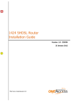
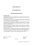
3.2.1.1 Segment Display Test
1. Turn the scale on, all segments are enabled and displayed breifly, then the model number
of the scale followed by a software revision number. This is a segment display test. Figure
3-1 is a full display test.
12 12
Com
tbz NET B/G
Com 12
tbz NET
kg %Pcs
kg Pcs
%0
Weighing Display
Auto Opt
50
100
Counting Display
Figure 3-1. Segment Displays
3-1
CHAPTER 3 MAINTENANCE PROCEDURES
3.2.2 Menu Structure
Programmable features of the Ranger Scales are contained in menus which are accessed through
the front panel control switches. Figure 3-2 illustrates the Ranger Counting Scale, Figure 3-3
illustrates the Ranger Weighing Scale. Figure 3-4 illustrates the service menu structure.
SETUP
CALIBRATION
CAL
Span
-0(full capacity weight)
-doneLin
-0(50% capacity weight)
(100%capacity weight)
-doneEndCAL
READ
Setup
reset
YES, NO
LFT
ON, OFF, CAN
quit
Cal Un
kg, lb
quit
Grad
0.0005, 0.001,
0.002, 0.005,
0.0001,0.0002,
quit
APPL IC
Stand
Fill
quit
Bac lt
ON,OFF
quit
Aut Opt
ON,OFF
A-Add
ON,OFF
List
End set
Read
reset
YES, NO
Al
med
high
low
quit
Unit 1
Unit 1LB , Unit 1g, Unit 1kg,
Unit 1 OZ
quit
Unit 2
Unit 2LB , Unit 2g, Unit 2kg,
Unit 2 OZ
quit
Azt
0.5d, 1d, 3d, OFF
quit
A-t
OFF, ON
quit
Aot
YES, NO
quit
Rzd
OFF, ON
quit
End rd
Hidden when LFT is ON.
Can be viewed but not changed when LFT is ON.
Figure 3-2. Ranger Counting Scale Menus (Sheet 1 of 2).
3-2
CHAPTER 3 MAINTENANCE PROCEDURES
3.2.2 Menu Structure (Cont.)
RS232-1
RS232-2
LOCKOUT
rs232-2 Com 2
Loc
rs232-1 Com 1
reset
reset
Cal
YES,
NO
YES, NO
ON, OFF
Mode
Mode
quit
Print, On Stb, Stb
Print, On Stb, Stb
Setup
only, Cont, Dialog,
only, Cont, Dialog,
ON, OFF
Disp 2, Ref 2, Bulk2
Disp 2, Ref 2, Bulk2
quit
quit
quit
Read
baud
baud
ON, OFF
300,600,1200, 2400,
300,600,1200, 2400,
quit
4800, 9600, 19200,
4800, 9600, 19200,
RS232-1
quit
quit
ON, OFF
Parity
Parity
quit
7 even, 7 no p,
7 even, 7 no p,
RS232-2
8 no p, 7 odd
8 no p, 7 odd
ON, OFF
quit
quit
quit
Stop
Stop
Locset
1, 2
1, 2
ON, OFF
quit
quit
quit
Handsh
Handsh
Endloc
YES, NO
YES, NO
quit
quit
quit
Store ?
Defstr
Defstr
Header
Header
ON, OFF
ON, OFF
Gross
Gross
ON, OFF
ON, OFF
Net
Net
ON, OFF
ON, OFF
Tare
Tare
ON, OFF
ON, OFF
PCS
PCS
ON, OFF
ON, OFF
APW
APW
ON, OFF
ON, OFF
REF CT
REF CT
ON, OFF
ON, OFF
4
L
INF
4 L INF
ON, OFF
ON, OFF
F
Feed
F Feed
ON, OFF
ON, OFF
LN For
LN For
Single, multi,
Single, multi,
End rs2
End rs1
Figure 3-2. Ranger Counting Scale Menus (Sheet 2 of 2).
3-3
QUIT
Quit
Store ?
CHAPTER 3 MAINTENANCE PROCEDURES
3.2.2 Menu Structure (Cont.)
CALIBRATION
READ
SETUP
CAL
Span
-0(full capacity weight)
-doneLin
-0(50% capacity weight)
(100% capacity weight)
-doneEndCAL
Setup
reset
res sp
LFT
ON, OFF,CAN
quit
CAL UN
Lb, Kg
Grad
0.0005, 0.001,
0.002, 0.005,
0.0001,0.0002,
quit
APPL IC
Stand
Fill
quit
Bac lt
ON,OFF
quit
List
Print
End set
Read
reset
res rd
Al
med
high
low
quit
Unit 1
Unit 1LB , Unit 1g, Unit 1kg,
Unit 1 OZ
quit
Unit 2
Unit 2LB , Unit 2g, Unit 2kg,
Unit 2 OZ
quit
Azt
0.5d, 1d, 3d, OFF
quit
A-t
OFF, ON
quit
Aot
YES, NO
quit
Rzd
OFF, ON
quit
End rd
Hidden when LFT is ON.
Can be viewed but not changed when LFT is ON.
Figure 3-3. Ranger Weighing Scale Menus (Sheet 1 of 2).
3-4
CHAPTER 3 MAINTENANCE PROCEDURES
3.2.2 Menu Structure (Cont.)
RS232-1
LOCKOUT
RS232-2
rs232-2 Com 2
rs232-1 Com 1
reset
reset
reset rs
reset rs
Mode
Mode
Print, On Stb, Stbonly,
Print,On Stb, Stbonly,
Cont, Dialog, Disp 2
Cont, Dialog, Disp 2
quit
quit
baud
baud
300,600,1200, 2400,
300,600,1200, 2400,
4800, 9600, 19200,
4800, 9600, 19200,
quit
quit
Parity
Parity
7 even, 7 no p,
7 even, 7 no p,
8 no p, 7 odd
8 no p, 7 odd
quit
quit
Stop
Stop
1, 2
1, 2
quit
quit
Handsh
Handsh
YES, NO
YES, NO
quit
quit
Defstr
Defstr
Header
Header
ON, OFF
ON, OFF
Gross
Gross
ON, OFF
ON, OFF
Net
Net
ON, OFF
ON, OFF
Tare
Tare
ON, OFF
ON, OFF
4 L INF
4 L INF
ON, OFF
ON, OFF
F Feed
F Feed
ON, OFF
ON, OFF
LN For
LN For
Single, multi,
Single, multi,
End rs1
End rs1
Loc
Cal
ON, OFF
quit
Setup
ON, OFF
quit
Read
ON, OFF
quit
RS232-1
ON, OFF
quit
RS232-2
ON, OFF
quit
Locset
ON, OFF
quit
Endloc
quit
Figure 3-3. Ranger Weighing Scale Menus (Sheet 2 of 2).
3-5
QUIT
Quit
Store ?
CHAPTER 3 MAINTENANCE PROCEDURES
3.2.2 Menu Structure (Cont.)
RAMP
SNR
RANGE
GEO
LIN
CAL
Display
Duty Cycle
Display/
Edit S/N
SELECT
RANGE
SELECT
GEO
FACTOR
START
LIN CAL
START
SPAN CAL
Figure 3-4. Ranger Service Menu Structure .
3.2.3 Ranger Counting Switch Functions
There are two sets of button switches located on the front panel of the Ranger Counting Scale. The
six button switches located directly under the display are used for counting functions. The four button
switches located below the six switches provide basic scale operation and menu setups. Please read
the following information before pressing any of these buttons.
Clear
BUTTONS
APW
Scale
Select
Count
Weight
Sample
10
Sample
Size
FUNCTION
Clear
Short press -Average Piece Weight (APW) is cleared and scale returns to weighing
mode.
APW
Short press - Average Piece Weight - one piece reference weight is displayed for 3
seconds.
Scale
Select
Switches the display between scale 1 (host) and scale 2 (remote). If 2 scales are
connected, the functions zero, G/N/T & tare will be executed on the scale that is
currently on the host LCD.
Count
Weight
Short press - Switches from weighing to counting mode.
Sample 10
Short press - Takes average piece weight for a sample size of 10.
Sample Size Long press and hold - scrolls through 5, 15, 20, 25, 30, 50 and 100 pieces - sample
size.
Short press - Takes average piece weight for sample number of pieces shown in
display.
3-6
CHAPTER 3 MAINTENANCE PROCEDURES
3.2.3 Ranger Counting Switch Functions
ONZERO
OFF
BUTTONS
PRINT
G/N/T
UNITS
MENU
PRIMARY FUNCTION
TARE
SECONDARY FUNCTION
ON/ZERO
OFF
Short press - Turns scale ON if OFF.
Long press - Turns scale OFF if ON.
When scale is ON, short press zeros the
scale.
PRINT
Short press - Sends current weight to
printer.
Long press - Changes UNITS.
When in MENU MODE: short press = NO.
UNITS
G/N/T
MENU
Short presses - Toggles display between When in MENU MODE: short press = YES.
Gross/Net/Tare if tare value is stored.
Noactionfor5secs.,scaledisplayreturnsto NET.
Long press - Enter MENU.
TARE
Short press - enter TARE.
3.2.4 Ranger Counting Scale Menu Operation
This section describes the menu operation. The menu permits matching the scale to specific
weighing needs. In the menu, you can change the settings of the scale and activate functions. The
Main Menu contains 7 sub menus. Each of the seven sub menus are described in detail in the
following sections.
CALIBRATION
SETUP
READ
RS232-1
RS232-2
LOCKOUT
QUIT
3.2.4.1 How to Enter the Menus
To enter the menus, press and hold the G/N/T MENU button until CAL appears. This is the first menu,
CALIBRATION. If LFT is ON, Setup appears first (CAL is hidden).
3.2.4.2 How to Select a Specific Menu
A short press on the PRINT UNITS button = NO. When in MENU MODE short presses will advance
to the next menu as shown above. When QUIT is reached, the next press on the PRINT UNITS button
will return to the CALIBRATION or SETUP menu.
3.2.4.3 How to Enter an Individual Menu
A short press on the G/N/T MENU button = YES and you can enter a specific menu.
3-7
s
CHAPTER 3 MAINTENANCE PROCEDURES
3.2.4 Ranger Counting Scale Menu Operation
3.2.4.4 How to Enter an Individual Menu Item
When in any menu, a short press on the G/N/T MENU button = YES and you can enter a specific menu
item. To advance through a given menu, make short presses on the PRINT UNITS =NO button.
3.2.4.5 How to Save and Store an individual menu item
When a menu item has been changed once the desired selection is shown, make a short press on
G/N/T MENU button, Quit appears on the display. If NO is selected by pressing the PRINT UNITS
button, the next menu item appears. If yes is selected by pressing G/N/TMENU, StorE? appears.
Pressing the G/N/T MENU button will store the change and return the scale to a weighing mode. If NO
is selected, the menu change is ignored and the scale is returned to weighing mode.
3.2.4.6
How to Quit the Menus
A short press on the PRINT UNITS button = NO. When in MENU MODE, short presses will advance
through the menus until QUIT is reached. To quit, make a short press on the G/N/T MENU button,
StorE? appears, answer YES to save changes and the scale returns to the weighing mode, or NO to
ignore changes and return to the weighing mode.
3.2.4.7
Calibration Menu
The Calibration menu contains entries for span or linearity
calibration.
Function/Display
Available Settings
Application
Span Calibration
Eight calibration values are
available for each balance.
Calibrate balance full scale in
either kg or lb units.
Zero, mid-range and full
scale calibration points.
Three point calibration for
maximum accuracy.
Displays after successful calibration.
Signifies end of calibration.
Linearity Calibration
End Calibration
3-8
CHAPTER 3 MAINTENANCE PROCEDURES
3.2.4 Ranger Counting Scale Menu Operation (Cont.)
3.2.4.8
Setup Menu
The Setup menu contains entries for LFT, calibration units,
graduations, processing, back light, list and end set. See table
below for details. Bold equals factory default settings.
Function/Display
Available Settings
Application
Reset
res sp
Press G/N/T MENU =reset all
menu items to their factory settings. Press PRINT UNITS
=NO, advances to next menu.
OFF
ON
CAN
Legal for trade applications
when set ON or CAN.
Kg (default for dual range)
lb (default for single range)
Either kg or lb can be selected
as the calibration unit.
0.001, 0.002, 0.005, 0.0001,
0.0002, 0.0005
This is the graduation size and
available options vary with the
capacity of the scale.
Stand-Standard
Regular weighing.
FILL-Filling
Dispensing or filling applications.
ON
OFF
Back light can turned on or off.
ON
OFF
Automatically updates the
sample weight.
Legal for trade
Calibration unit
Graduation
Application
Back Light
Auto optimization
(Counting only)
3-9
CHAPTER 3 MAINTENANCE PROCEDURES
3.2.4 Ranger Counting Scale Menu Operation (Cont.)
3.2.4.8
Setup Menu (Cont.)
Function/Display
Available Settings
Application
Auto add
Calculates the minimum reference sample for the most accurate counting.
ON
OFF
List
Prints a setup list to the
RS232 when Mode is set
to PRINT on Stability or
Stable Only.
Print
End Settings
End of setup menu.
3.2.4.9
End of setup menu. When
selected by pressing G/N/T
MENU button, display advances to READ MENU.
Read Menu
The Read menu contains entries for reset, averaging level, unit 1,
unit 2, auto zero, auto tare, auto power off, retain zero data and
end. See table below for details. Bold equals factory default
settings.
Function/Display
Reset
Averaging level
Unit 1
Unit 2
Available Settings
Application
reset rd
Press G/N/T MENU =reset all
menu items to their factory settings. Press PRINT UNITS
=NO, advances to next menu.
Low, Med, High
Averaging level.
High=greater stability, Med= mid
stabilty, Low=less stability,
faster processing time.
g, kg, oz, lb
This is the first weighing unit.
g, kg, oz, lb
This is the alternate weighing
unit.
3-10
CHAPTER 3 MAINTENANCE PROCEDURES
3.2.4 Ranger Counting Scale Menu Operation (Cont.)
3.2.4.9
Read Menu (Cont.)
Function/Display
Available Settings
Application
Auto-Zero Tracking
0.5d, 1d, 3d, Off
Auto Tare
Settings minimize effects of temperature and small disturbances on the zero reading.
On
OFF
Enables automatic tare when
set to ON.
YES
NO
When set YES, scale turns off
after 5 minutes.
NOTE: Default is YES if battery
option is installed, else NO.
Auto Power Off
Retain Zero Data
ON
OFF
Retains stored zero point
when scale is turned off.
End of read menu.
End of Read menu, when selected, display advances to
RS232-1 menu.
End Settings
3.2.4.10 RS232-1/RS232-2 Menus
The RS232-1 menu provides the communication settings to port
1 (standard). RS232-2 is Port 2 which is an option and has exactly
the same settings. Bold equals factory default settings.
Com
1
Function/Display
Available Settings
Reset
reset rs
Mode
Com
1
Application
Press G/N/T MENU =reset all
menu items to their factory settings. Press PRINT UNITS
=NO, advances to next menu.
Print, on stb, stb only, cont,
dialog, disp 2, ref 2, bulk 2.
When LFT is set to ON or
CAN, the Print and cont
modes are not available and
the default mode for res rs
becomes stb only.
3-11
Selects mode of operation for
RS232. Print, print on stability,
stability only, continuous, dialog (interface), disp 2, reference
2, bulk 2.
CHAPTER 3 MAINTENANCE PROCEDURES
3.2.4 Ranger Counting Scale Menu Operation (Cont.)
3.2.4.10 RS232-1/RS232-2 Menus (Cont.)
Function/Display
Available Settings
Baud Rate
Com
1
Parity
Com
1
Application
300, 600, 1200, 2400, 4800,
9600, 19200
Various baud rates are available to match external equipment communication requirements.
7 Even, 7 No P, 8 No P, 7
Odd
Various parity settings are
available to accommodate external equipment requirements.
1
2
Two stop settings (1 or 2) are
available to accommodate external equipment requirements.
YES
NO
Software handshaking enabled/disabled.
Header, Gross, Net, Tare,
(PCS, APW, Ref CT, 4 L in f,
F feed, LN for
Determines what is printed via
print command. Selects a
string of data to be printed;
header, gross, net, tare,
pieces, average piece weight,
reference count, 4 line feed,
form feed, multi or single string
per line.
End of RS232 menu.
End of RS232-1 menu, when
selected, display advances to
RS232-2 menu. End of RS2322, display advances to LOC
menu.
Stop
Com
1
Com
1
Com
1
Handshake
Default String
End Settings
Com
1
3-12
CHAPTER 3 MAINTENANCE PROCEDURES
3.2.4 Ranger Counting Scale Menu Operation (Cont.)
3.2.4.11 Lockout Menu
This menu allows software locking and unlocking of the calibration, setup, read, RS232-1, RS232-2, menus. Turning individual
menu locks ON and OFF prevents accidental changes to menu
parameters. The locks can be turned OFF to change the parameters. However, once the Locset is set to ON, the menus can only
be unocked by removing the scale bottom cover and using the
Unlock switch.
Function/Display
Calibration
Available Settings
Application
ON
OFF
An ON setting locks out
the calibration menu.
ON
OFF
An ON setting locks out
the setup menu.
ON
OFF
An ON setting locks out
the read menu.
ON
OFF
An ON setting locks out
the RS232-1 menu.
ON
OFF
An ON setting locks out
the RS232-2 menu.
Setup
Read
RS232-1
RS232-2
Lockset
Locks/unlocks all of the Lockout menu. When set on, locks
all software settings in this
menu. LOCSET can only be
set to OFF by pressing the UNLOCK switch under the scale.
ON
OFF
Endlock
End of LOC menu
3-13
CHAPTER 3 MAINTENANCE PROCEDURES
3.2.4 Ranger Counting Scale Menu Operation (Cont.)
3.2.4.12 Quit Menu
End of menus. - YES,- prompts to store, saves all
changes, and then will go to a weighing mode,
NO, ignores changes and returns to the weighing
mode.
3.2.5 Ranger Weighing Scale Switch Functions
The button switches located on the front panel of the scale provide several functions. Please read the
following information before pressing any of these buttons.
ON/ZERO
OFF
BUTTONS
ON/ZERO
OFF
PRINT
UNITS
G/N/T
MENU
TARE
PRINT
G/N/T
UNITS
MENU
PRIMARY FUNCTION
TARE
SECONDARY FUNCTION
Short press - Turns scale ON if OFF. When scale is ON, short press zeros the scale.
Long press - Turns scale OFF if ON.
Short press - Sends current weight
When in MENU MODE: short press = NO.
to the printer.
Long press - Changes UNITS.
Short presses - Gross/Net/Tare.
When in MENU MODE: short press = YES.
No action for 5 secs., scale returns NET.
Long press - Enter MENU.
Short press - enter TARE value.
3.2.6 Ranger Weighing Scale Menu Functions
This section contains information on the Ranger Weighing Scale menu. The menu allows you to
match your scale to your specific weighing needs. In the menu, you can change the settings of your
scale and activate functions. The Main Menu contains 7 sub menus. Each of the seven sub menus
are described in detail in the following sections.
CALIBRATION
SETUP
READ
RS232-1
RS232-2
LOCKOUT
QUIT
3.2.6.1 How to Enter the Menus
To enter the menus, press and hold the G/N/T MENU button until CAL appears. This is the first menu,
CALIBRATION. If LFT is ON, Setup appears first (CAL is hidden).
3.2.6.2 How to Select a Specific Menu
A short press on the PRINT UNITS button = NO. When in MENU MODE short presses will advance
to the next menu as shown above. When QUIT is reached, the next press on the PRINT UNITS button
will return to the CALIBRATION or SETUP menu.
3-14
CHAPTER 3 MAINTENANCE PROCEDURES
3.2.6 Ranger Weighing Scale Menu Functions (Cont.)
3.2.6.3 How to Enter an Individual Menu
A short press on the G/N/T MENU button = YES and you can enter a specific menu.
3.2.6.4 How to Enter an Individual Menu Item
When in any menu, a short press on the G/N/T MENU button = YES and you can enter a specific menu
item. To advance through a given menu, make short presses on the PRINT UNITS =NO button.
3.2.6.5
How to Save and Store an Individual Menu item
When a menu item has been changed once the desired selection is shown, make a short press on
G/N/T MENU button, Quit appears on the display. If NO is selected by pressing the PRINT UNITS
button, the next menu item appears. If yes is selected by pressing G/N/TMENU, StorE? appears.
Pressing the G/N/T MENU button will store the change and return the scale to a weighing mode. If NO
is selected, the menu change is ignored and the scale is returned to weighing mode.
3.2.6.6
How to Quit the Menus
A short press on the PRINT UNITS button = NO. When in MENU MODE, short presses will advance
through the menus until QUIT is reached. To quit, make a short press on the G/N/T MENU button,
StorE? appears, answer YES to save changes and scale returns to the weighing mode, or NO to ignore
changes and return to the weighing mode.
3.2.6.7
Calibration Menu
The Calibration menu contains entries for span or linearity
calibration.
Function/Display
Available Settings
Application
Span Calibration
Eight calibration values are
available for each balance.
Calibrate balance full scale in
either kg or lb units.
Zero, mid-range and full
scale calibration points.
Three point calibration for
maximum accuracy.
Displays after successful calibration.
Signifies end of calibration.
Linearity Calibration
End Calibration
3-15
CHAPTER 3 MAINTENANCE PROCEDURES
3.2.6 Ranger Weighing Scale Menu Functions (Cont.)
3.2.6.8
Setup Menu
The Setup menu contains entries for LFT, calibration units,
graduations, processing, back light, list and end set. See table
below for details. Bold equals factory default settings.
Function/Display
Available Settings
Reset
Application
res sp
Press G/N/T MENU =reset all
menu items to their factory settings. Press PRINT UNITS
=NO, advances to next menu.
OFF
ON
CAN
Legal for trade applications
when set ON or CAN.
Kg (default for dual range)
lb (default for single range)
Either kg or lb can be selected
as the calibration unit.
Legal for trade
Calibration unit
Graduation
0.001, 0.002, 0.005, 0.0001,
0.0002, 0.0005
Application
Back Light
This is the graduation size and
available options vary with the
capacity of the scale.
Stand-Standard
Regular weighing.
FILL-Filling
Dispensing or filling applications.
ON
OFF
Back light can turned on or off.
Print
Allows printing of complete
scale setup.
List
End Settings
End of setup menu.
3-16
End of setup menu. When selected by pressing G/N/T
MENU button, display advances to READ MENU.
CHAPTER 3 MAINTENANCE PROCEDURES
3.2.6 Ranger Weighing Scale Menu Functions (Cont.)
3.2.6.9
Read Menu
The Read menu contains entries for reset, averaging level, unit 1,
unit 2, auto zero, auto tare, auto power off, retain zero data and
end. See table below for details. Bold equals factory default
settings.
Function/Display
Reset
Averaging level
Unit 1
Unit 2
Auto-Zero Tracking
Available Settings
Application
Press G/N/T MENU =reset all
menu items to their factory settings. Press PRINT UNITS
=NO, advances to next menu.
reset rd
Low, Med, High
Averaging level.
High=greater stability, Med= mid
stabilty, Low=less stability,
faster processing time.
g, kg, oz, lb
This is the first weighing unit.
g, kg, oz, lb
This is the alternate weighing
unit.
0.5d, 1d, 3d, Off
Settings minimize temperature
and small disturbances on the
zero reading.
ON
OFF
Enables automatic tare
when set to ON.
YES
NO
When set YES, scale turns off
after 5 minutes.
NOTE: Default is YES if battery
option is installed, else NO.
ON
OFF
Retains stored zero point
when scale is turned off.
End of read menu.
End of Read menu, when selected, display advances to
RS232-1 menu.
Auto Tare
Auto Power Off
Retain Zero Data
End Read Settings
3-17
CHAPTER 3 MAINTENANCE PROCEDURES
3.2.6 Ranger Weighing Scale Menu Functions (Cont.)
3.2.6.10 RS232-1/RS232-2 Menus
Com
1
The RS232-1 menu provides the communication settings to port
1 (standard). RS232-2 is Port 2 which is an option and has exactly
the same settings. Bold equals factory default settings.
Function/Display
Available Settings
Reset
Mode
1
Com
Baud Rate
Com
1
Parity
Com
1
Application
reset rs
Press G/N/T MENU =reset all
menu items to their factory settings. Press PRINT UNITS
=NO, advances to next menu.
Print, on stb, stb only, cont,
dialog, disp 2, ref 2, bulk 2.
When LFT is set to ON or
CAN, the Print and cont
modes are not available and
the default mode for res rs
becomes stb only.
Selects mode of operation for
RS232. Print, print on stability,
stability only, continuous, dialog (interface), disp 2.
300, 600, 1200, 2400, 4800,
9600, 19200
Various baud rates are available to match external equipment communication requirements.
7 Even, 7 No P, 8 No P, 7
Odd
Various parity settings are
available to accommodate external equipment requirements.
1
2
Two stop settings (1 or 2) are
available to accommodate external equipment requirements.
YES
NO
Software handshaking enabled/disabled.
Stop
Com
1
Com
1
Handshake
3-18
CHAPTER 3 MAINTENANCE PROCEDURES
3.2.6 Ranger Weighing Scale Menu Functions (Cont.)
3.2.6.10 RS232-1/RS232-2 Menus (Cont.)
Default String
Com
1
Header, Gross, Net, Tare,
(PCS, APW, Ref CT, 4 L in f,
F feed, LN for
Determines what is printed via
print command. Selects a
string of data to be printed;
header, gross, net, tare,
pieces, average piece weight,
reference count, 4 line feed,
form feed, multi or single string
per line.
End of RS232 menu.
End of RS232-1 menu, when
selected, display advances to
RS232-2 menu. End of RS2322, display advances to LOC
menu.
End Settings
Com
1
3.2.6.11 Lockout Menu
This menu allows software locking and unlocking the calibration,
setup, read, RS232-1, RS232-2, menus. Locking is done to limit
menu access or for LFT applications. Once LocSet is set ON, the
menu can only be unlocked by a switch on the circuit board of the
scale.
Function/Display
Calibration
Available Settings
Application
On
OFF
An ON setting locks out
the calibration menu.
On
OFF
An ON setting locks out
the setup menu.
On
OFF
An ON setting locks out
the read menu.
Setup
Read
3-19
CHAPTER 3 MAINTENANCE PROCEDURES
3.2.6.11 Lockout Menu (Cont.)
Function/Display
Available Settings
Application
RS232-1
ON
OFF
An ON setting locks out
the RS232-1 menu.
ON
OFF
An ON setting locks out
the RS232-2 menu.
RS232-2
Lockset
Locks/unlocks all of the Lockout menu. When set on, locks
all software settings in this
menu. LOCSET can only be
set to OFF by pressing the UNLOCK switch under the scale.
ON
OFF
Endlock
End of LOC menu
3.2.6.12 Quit Menu
End of menus. - Yes,- prompts to store and then
will go to a weighing mode, No, returns to Calibration menu.
3-20
CHAPTER 3 MAINTENANCE PROCEDURES
3.2.7 Calibration and Sealing
Ranger Counting and Weighing scales offer a choice of two calibration methods: Span Calibration,
and Linearity Calibration.
Span - Span calibration ensures that the scale reads within specifications using two weight values:
zero and a weight value close to 100% of the full capacity. Special software features enable you to
perform a span calibration at a number of lesser values which varies with the model of the scale.
Linearity - Linearity calibration minimizes deviation between actual and displayed weights within the
scale’s weighing range. Three weight values are used: zero, a weight value at midpoint of the scale’s
weighing range, and a weight value at or near the specified capacity.
For best results, calibrate at or near full capacity. Calibration unit can be set to either kg or lb. When
the scale is used in Legal for trade applications, the calibration menu is locked out and is not
accessable. This is to prevent unauthorized personnel from changing calibration. Before beginning
calibration, make sure masses are available. If you begin calibration and realize calibration masses
are not available, exit the menu with a short press of the ON/ZERO OFF button. The scale will retain
previously stored calibration data. Calibration should be performed as necessary to ensure accurate
weighing. Masses required to perform the procedures should be in compliance with the specification
requirements of the scale being used.
3.2.7.1
Calibration Masses
Before beginning calibration, make sure masses are available. If you begin calibration and realize
calibration masses are not available, exit the menu. The scale will retain previously stored calibration
data. Calibration should be performed as necessary to ensure accurate weighing. Refer to Tables
1-1 and 1-2 which refer to the calibration points of the scales.
3.2.7.2
Calibration Procedure
NOTE: If the scale is sealed and is used for legal for trade, the seal
must be removed to gain access to the unlock switch located underneath the scale in order to calibrate the scale.
Access the menu by pressing and holding the G/N/T Menu button.
You have a choice of calibrating the scale using span or linearity
methods. Span calibration requires two points zero and full span.
Linearity requires three points. zero, mid-range and full span.
Span
Press G/N/T Menu button, -0- is displayed followed by mass value to
be placed on the platform. For example, a 3kg scale would normally
require 3kg for a span calibration. By pressing the PRINT UNITS
button repeatedly, a lesser value mass can be used. For example, a
3kg scale offers 2kg, 1.5kg, 1.2kg. 1kg, 0.9kg, 0.8kg and 0.7kg for full
3-21
CHAPTER 3 MAINTENANCE PROCEDURES
3.2.7.2
Calibration Procedure (Cont.)
span.
Place the indicated mass on the platform and press the G/N/T MENU
button.
If the calibration was successful, data is saved automatically.
Remove calibration masses from platform.
Linearity
When performing a linearity calibration, -0- is first displayed followed by the first mass and then a second mass.
3.2.7.3
Unlocking the Menus
Low Capacity Scale
If it necessary to recalibrate a scale which has been set up for
legal for trade use, or if the menu is locked, you will have to
remove the seal (paper or lead wire) at the bottom of the scale to
gain access to the unlock switch.
To unlock the menus, turn the scale off.
On low capacity scales, remove the existing seal and four cover
screws from the bottom of the scale. You will have to unscrew the
feet to access the screws.
Position the scale so the bottom is accessible.
NOTE: Do the next step carefully.
First, press and hold the unlock switch then, briefly press the ON/
ZERO OFF switch at the same time, release the unlock switch while
the software version is being displayed. LFT is now set to OFF
and LOCSET is set to OFF. LFT restrictions are no longer
enabled and items in the LOC menu may be changed.
3-22
CHAPTER 3 MAINTENANCE PROCEDURES
3.2.7.3
Unlocking the Menus (Cont.)
High Capacity Scale
On high capacity scales, remove the existing seal and six cover
screws from the bottom of the scale. You will have to unscrew the
feet to access the screws.
Position the scale so the bottom is accessible.
NOTE: Do the next step carefully.
First, press and hold the unlock switch then, briefly press the ON/
ZERO OFF switch at the same time, release the unlock switch while
the software version is being displayed. LFT is now set to OFF and
LOCSET is set to OFF. LFT restrictions are no longer enabled and
items in the LOC menu may be changed.
3.2.7.4
Weights and Measures Sealing
SEAL
After a weights and measures official has tested and approved the
scale, it must be sealed by installing the security plate with the
security screw.
Replace the bottom cover and secure with the cover screws.
Paper Seal
A paper seal may be placed over one of the screws at the back of
the scale underneath one foot.
Replace the four feet and turn the scale over.
LOW CAPACITY
SCALE
Lead Wire Seal
For regions requiring a lead wire seal, there are 2 cross drilled
screws at the rear of the scale. The screws can be used in the
location as supplied or as an alternate, one screw can be used to
replace one of the counter-sunk screws at the front of the scale.
(Under the leveling feet on small size Ranger Scales.)
HIGH
CAPACITY
SCALE
3-23
CHAPTER 3 MAINTENANCE PROCEDURES
3.2.8 Performance Tests
Accurate performance of the Ranger scales is determined by a series of three performance tests. The
displayed readings are compared with the tolerances listed in Table 3-1. Tolerance values are
expressed in counts. A one count change is equal to the last digit shown on the scale display.
TABLE 3-1. TYPES OF PERFORMANCE TESTS
PERFORMANCE TEST
Repeatability
Off Center Load
Linearity
3kg
6kg
±1
±1
±2
±1
±1
±2
TOLERANCE - COUNTS
12kg
30kg
±1
±1
±1
±1
±1
±2
60kg
±1
±1
±2
The following performance tests are used to evaluate the scale operation before and after repairs.
Each scale tested must meet the requirements specified in each test as well as the specifications listed
in Tables 1-3 through 1-6 depending upon the model. Before proceeding with the following tests, all
the procedures starting with paragraph 3.2 must have been accomplished on the scale first.
3.2.8.1
Repeatabilty Test
To conduct a Repeatability Test, proceed as follows:
1. With the scale calibrated, place a mass on the Platform equal to the capacity of the scale.
Record the reading.
2. Remove the mass from the Platform, the scale should return to 0g. Record the reading.
3. Repeat steps 1 and 2 ten more times. Subtract the lowest from the highest reading to
determine the difference. Maximum allowable difference is as listed in Table 3-1.
3-24
CHAPTER 3 MAINTENANCE PROCEDURES
3.2.8.2
Off-Center Load Test
The Off-Center Load Test is used to determine whether displayed weight values will be affected by
moving the sample to different areas of the Platform. See Figure 3-5.
Place 1/2 of the scale capacity in the center of the Platform (1). Press the ON/ZERO OFF button to return
the reading to zero. Move the mass halfway to the rear of the Platform and note the reading. Move the
mass halfway between the center and the left edge front of the Platform and note the reading. Repeat
this test for the right edge position and note the reading. Move the mass halfway to the front of the
Platform and note the reading. Note any differences in the displayed weight reading at all positions.
Maximum allowable change is per Table 3-1 for each of the listed scales four positions. Move back
to center and tare if neccessary after each reading.
MASS LOCATIONS
Figure 3-5. Off-Center Load Test Mass Locations.
3.2.8.3
Linearity Test
The Linearity test is used to determine the linearity of the scale throughout its operating range and is
in accordance with the specifications listed in Tables 1-3 through 1-6.
NOTE:
The scale must pass the Off-Center Load test and Repeatability Test
before the Linearity Test is performed.
This test is used to determine the linearity of the scale throughout its operating range.
Table 3-2 lists the suggested masses to be used for checking linearity on each scale model.
If the unit fails the linearity test, check the alignment of the transducer and re-assemble. If the transducer
has been replaced, carefully check the alignment.
TABLE 3-2. LINEARITY TEST MASSES
CAPACITY
3Kg
6Kg
12Kg
30Kg
60Kg
Ref. Mass.
100g
100g
100g
100g
100g
Load 1
750g
1.5kg
3kg
7.5kg
15kg
Load 2
1.5kg
Load 3
2.250kg
Load 4
3kg *
3kg
6kg
15kg
30kg
4.5kg
9kg
22.5kg
45kg
12kg *
30kg *
60kg *
6kg *
All masses are nominal values.
BE CERTAIN TO USE THE SAME REFERENCE MASS THROUGHOUT THE PROCEDURE.
* As close to full capacity as possible while allowing the 100g weight to read.
3-25
CHAPTER 3 MAINTENANCE PROCEDURES
3.2.8.3
Linearity Test (Cont.)
Before beginning:
•
Perform calibration.
Preliminary Weighings
Using the Load 3 and Load 4 weight values (Table 3-2), perform some preliminary weighings and make
sure the display returns to zero after weighing.
1. Place Load 3 on the center of the Platform, read the displayed weight, then remove Load 3.
If the display does not return to zero, press ON/ZERO/OFF and repeat this.
2. Repeat step 1 using Load 4.
After performing preliminary weighings, proceed with checking Linearity. If the scale does not return
to zero, it must be repaired.
Test
1. Place the reference mass on the center of the Platform and record the exact value (all decimal
places) displayed.
2. Remove the reference mass and verify that the display returns to zero. If it does not, disregard
the reading, press ON/ZERO/OFF to rezero the display and take that reading again. See
note above.
3. Place Load 1 on the center of the Platform and press ON/ZERO/OFF.
4. Add the reference mass to the Platform and record the exact value displayed.
5. Remove the reference mass and verify that the display returns to zero. If it does not, disregard
the reading, press ON/ZERO/OFF to rezero the display and take that reading again.
NOTE:
If after several attempts the display fails to return to zero, a
repeatability problem is indicated and the scale must be
serviced by an Ohaus Product Service Specialist.
6. Repeat steps 3 through 5 using Load 2, Load 3 and Load 4 as applicable.
7, Compare the reference weight readings. They should agree per table 3-1.
3-26
CHAPTER 3 MAINTENANCE PROCEDURES
3.2.9 RS232 Interface Test
The RS232 Interface in the Ranger scale can have its performance monitored using an external printer
or computer connected to the scale.
The RS232 Interface is a bi-directional interface which enables the scale to communicate with a printer
or computer equipped with an RS232 serial port. An RS232 menu is in the scale. This menu enables
various parameters such as Baud rate, Data bits, Stop Bits and Parity to be set in the scale.
The RS232 menu provides communication parameters which can be set to accommodate external
printers or computers. It contains eight submenus: Reset, Node, Baud, Parity, Stop, Handshake,
Default String, and End RS menu which enable you to program RS232 port parameters.
Refer to RS232 menu and make sure all communications parameters are properly set.
3.2.9.1
Connecting the RS232 Interface
When the interface is connected to a computer, two way communication between the computer and
scale is possible using the commands outlined in the RS232 Command Table 3-3. See Figure 3-5 for
connections. When the scale is connected directly to a printer, displayed data can be output at any time
by simply pressing PRINT UNITS.
1
2
3
4
5
6
7
8
9
Data Out (TXD)
Data In (RXD)
1
Ground
2
6
3
7
4
8
5
9
Figure 3-6. RS232 Interface Pin Connections.
3-27
CHAPTER 3 MAINTENANCE PROCEDURES
3.2.9.1
Connecting the RS232 Interface (Cont.)
RS232 Commands
All communication is accomplished using standard ASCII format. Only the characters shown in the
RS232 Command Table 3-3 are acknowledged by the scale. Invalid command response "ES" error
indicates the scale has not recogonized the command. Commands sent to the scale must be
terminated with a line feed (LF) or carriage return-line line feed (CRLF). Data output by the scale is
always terminated with a carriage return - line feed (CRLF).
TABLE 3- 3. RS232 COMMANDS
Command
Character Description
0S
Print weight (stable or unstable) after P cmd.
1S
Print stable weight after P cmd.
SA
Print on stability. *Send final stable weight value.
CA
Continuous Print. Prints weight string w/o default string information
xxxxA
Interval Print xxxx= Print Interval (1-3600 sec) (0A turns off interval printing)
P
*Print display data (see 0S and 1S) Prints stable data only when LFT is ON.
Z
Same as pressing Zero button.
T
Same as pressing Tare button.
C
Begin span calibration
L
Begin linearity calibration.
XT
Download Tare value in grams. Uses unit set as Unit 1.
SN
Show serial number
H 1 (1-5)
1 to 5 header lines are available with 24 characters per line; enter H space, then text in quotations.
See below.
V
Sends scale ID and software version to the RS232 Port. Ranger r-x.xx or Ranger C rc-x.xx
3.2.10
Print Test
1. Remove all weight from the platform.
2. Press the ON/ZERO/OFF button once, 0.0g should be displayed.
3. Place a mass on the Platform.
4. Press Print UNITS button, the computer and or a printer should indicate the mass value.
NOTE: Print commands entered through the computer are temporary. When the scale is turned off,
it will return to scale menu settings when turned on
again.
3.2.11
Visual Inspection
1. Check that FCC and serial number labels are in place and properly affixed to the scale.
2. Check for nicks and scratches and other imperfections. Clean and repair as necessary.
3-28
CHAPTER 3 MAINTENANCE PROCEDURES
3.3
REPAIR PROCEDURES
This section describes how to change individual components of the Ranger scales. When doing this,
please refer to the exploded view drawings and spare parts lists in section 4.
Important: after replacing components, a functional check of the scale must always be carried out.
3.3.1 Replacing the Keypad Membrane
• Lift up the defective keypad membrane (if necessary carefully prying it up with a knife) and
gently peel it off the scale.
Note: Take care that the specification label is not damaged when the membrane is
removed!
• Carefully clean the display mounting plate and window (removing all traces of adhesive).
• Make sure that the specification label is in its correct position (must be visible through the
window in the keypad membrane), then peel off the protective film from the new membrane
and carefully affix the latter to the display mounting plate.
• Press the keypad membrane down uniformly.
3.3.2 Replacing the AC Adapter
Note: The AC adapter has a fuse as overcurrent protection. For safety reasons this fuse cannot
be replaced, and the AC adapter must therefore be replaced completely if the fuse blows. This
applies only to scales that are connected directly to the AC power line (without rechargeable
battery and external AC adapter).
• Unscrew the adjustable feet and remove them.
• Undo the bottom plate retaining screws, removing them and the plate itself.
• Disconnect the AC adapter cable from the analog PCB.
• Remove the AC adapter (held on by an adhesive patch) from the wall of the housing . If
necessary, carefully insert a flat blade (knife or screwdriver) between adapter and housing
and pry them apart. Remove all traces of adhesive from the housing.
• Undo the 4 screws holding the blanking plate in place (rear panel of scale) and remove the
plate.
• Slide the AC adapter power cord grommet out of the blanking plate. Remove the AC adapter
from the scale.
• Place the new AC adapter in the scale and fix it in place with a new adhesive patch.
• Slide the power cord grommet into the blanking plate slot and screw the plate in place.
• Plug the AC adapter output cable onto the analog PCB.
• Replace the bottom plate and the adjustable feet.
3-29
CHAPTER 3 MAINTENANCE PROCEDURES
3.3.3 Replacing the Internal Rechargeable Battery
Ranger scales that include /1 or /3 in their model numbers contain an internal rechargeable battery.
These batteries have a finite life expectancy and may require replacement at some time during the life
of the scale.
Battery life is effected by factors such as ambient temperature, method of charging, depth of discharge,
and the amount of time between charge and discharge.
Indications of a failing battery may include:
•
•
•
•
A reduction in operating time between charging and the low battery condition.
A continuous low battery condition even after charging.
A scale that cannot be operated without the power pack being connected.
A scale that will not power on even with the power pack connected. *
To replace the rechargeable battery follow the procedure below.
• With the scale inverted, unscrew the adjustable feet and remove them.
• Undo the bottom plate retaining screws, removing them and the plate itself.
• On small platform models lift the two ribbon cables out from the gap that runs along the edge
of the battery. Tuck these cables out of the way until the new battery is installed.
• Remove the battery (held on by an adhesive patch) from the inner wall of the housing. If
necessary, carefully insert a flat blade (knife or screwdriver) between the battery and
housing and pry them apart. Remove all traces of adhesive from the housing. Caution:
Because the battery case is made of plastic do not apply excessive pressure to the battery.
• Remove two connectors from the battery terminals. The old battery should be sent to an
appropriate recycling center.
• Remove one side of protective covering from a new adhesive patch. (The adhesive patch
is the same as that used for mounting of an internal power pack.) The patch is applied to the
side of battery where the manufacturer information is printed. This should also be the side
closest to power terminals. Center the patch on the battery with the long edge of the patch
aligned with the upper long edge of the battery case, (the stepped edge).
• Set the new battery to the side of the housing with the adhesive patch side facing away from
the housing and the positive, (“+”) terminal of battery towards the rear of the scale. Attach
the Red wire’s connector to the positive, (“+”) terminal of battery, attach the Blue wire’s
connector to the negative, (“-“) terminal of battery.
3-30
CHAPTER 3 MAINTENANCE PROCEDURES
3.3.3 Replacing the Internal Rechargeable Battery (Cont.)
• The battery is installed against the inner housing wall that encloses the transducer compart
ment. The battery is installed terminal side first with the positive, (“+”) terminal of battery
towards the rear of the scale. Remove the remaining covering from the adhesive patch. As
the battery is first lowered into the housing lightly pull the red and blue wires straight back
along the outer edge of + terminal connector. As the battery is further lowered be sure that
these wires are not pinched between any part of the housing and battery. Before allowing
the tape to stick to the housing temporarily allow the battery to rest on the plastic terminals.
Recheck that the red and blue wires are not pinched. When correctly in place the bottom of
the battery must be at or slightly below the height of the inner housing wall. Slide the battery
fully forward toward the display board compartment then press the battery firmly against the
inner housing wall to attach the adhesive patch.
• Tuck the extra length of battery wires into the housing between the small PCB and the battery.
On small platform models replace the two ribbon cables back into the slot between the inner
housing wall and the battery. Insure that no wiring will be pinched when the bottom plate is
installed.
• Replace the bottom plate and the adjustable feet.
*A small power supply PCB is installed with the battery option. This PCB contains a
replaceable fuse that provides overcurrent protection. A scale that will not power on should
have this fuse checked prior to suspecting a defective battery.
3-31
CHAPTER 3 MAINTENANCE PROCEDURES
3.3.4 Replacing the Analog PCB
• Unscrew the adjustable feet and remove them.
• Undo the bottom plate retaining screws, removing them and the plate itself.
• Disconnect weighing cell cable, connecting cable to the digital PCB and the AC adapter
output cable from the analog PCB.
• Pull off the two spring clips from the analog PCB and remove it.
• Fit the new analog PCB and fix it in place with the spring clips.
• Connect the weighing cell cable, the A/D cable from the digital PCB and the AC adapter
output cable to the analog PCB.
• Replace the bottom plate and the adjustable feet.
Note: After replacing the analog PCB all scale data must be entered again in service mode, plus
all scale settings! Following this the scale must be recalibrated and, if necessary, linearized.
3.3.5 Replacing the Display Mounting Plate, Display Unit and Digital PCB
The display mounting plate is located underneath the keypad membrane and is located in the scale
housing by 6 snaps. The display unit comprises the digital PCB, the liquid crystal display (LCD) and
the backlighting unit. It is held in place on the mounting plate by snaps. The digital PCB is connected
to the analog PCB and the RS232C interface by two ribbon cables.
3.3.5.1 Preliminary Work
• Unscrew the adjustable feet and remove them.
• Undo the bottom plate retaining screws, removing them and the plate itself.
•
Undo the retaining screw which fastens the display unit to the mounting plate.
• Pull back the two front cantilever snaps holding the display unit to release it, raise the front
edge of the display unit and withdraw it from the rear snaps.
• Disconnect the RS232 cable and the connecting cable to the analog PCB from the digital
PCB. Remove the display unit.
3-32
CHAPTER 3 MAINTENANCE PROCEDURES
3.3.5.2 Replacing the Display Mounting Plate
Note: In order to replace the display mounting plate, the keypad membrane must be removed.
This cannot then be reused and must also be replaced.
• Remove keypad membrane.
• Push the 3 cantilever snaps at the front edge of the display mounting plate inwards to release
the plate and remove it to the front.
• Insert the new display mounting plate into the aperture so that it clicks into place.
• Apply the new self-adhesive keypad membrane.
3.3.5.3 Replacing the Liquid Crystal Display (LCD) or the Backlighting Unit
• Place the display unit with the digital PCB downwards on a static protective surface.
• Disconnect the backlighting ribbon cable from the digital PCB.
• Carefully insert a flat blade screwdriver (size 4) between the digital PCB and the backlighting
unit immediately adjacent to the
connectors.
• With the screwdriver pry the liquid crystal display and the backlighting unit out of the socket
strips. When doing this, lever the shaft of the screwdriver against the edge of the digital PCB.
Never lever the tip of the screwdriver against the surface of the PCB, as this could damage
the PCB.
• Place the new backlighting unit onto the digital PCB (it snaps into place on the board).
• Carefully place the LCD onto the backlighting unit and ensure that the connector pins are
correctly aligned with the socket strips. When correctly positioned, the ends of the LCD and
backlighting unit are flush. Use a flat object such as a ruler to exert a uniform pressure on the
LCD and gently push it home.
• Push the backlighting unit ribbon cable connector onto the digital PCB pins.
3.3.5.4 Replacing the Digital PCB
• Remove the LCD and backlighting unit as described in the previous subsection.
• Remove the EPROM (if fitted) from its socket.
• Fit LCD and backlighting unit onto the new digital PCB. Where applicable, Fit the EPROM.
3-33
CHAPTER 3 MAINTENANCE PROCEDURES
3.3.6 Final Reassembly
• Connect the RS232 cable and the cable from the analog PCB to the digital PCB.
• Engage the display unit under the rear snaps of the display mounting plate and then lower
its front edge until it snaps into place. Fit the retaining screw.
•
Replace the bottom plate and adjustable feet.
3.3.7 Replacing the Software
Note: With Ranger scales it is not possible simply to replace the software, since this is permanently
programmed in the microcontroller on the analog PCB. To replace the software in these scales,
therefore, it is necessary to replace the analog PCB. The following description refers to scales that
have a plug-in EPROM on the digital PCB.
• Unscrew the adjustable feet and remove them.
•
Undo the bottom plate retaining screws, removing them and the plate itself.
•
Undo the retaining screw which fastens the display unit to the mounting plate.
•
Pull back the two front cantilever snaps holding the display unit to release it, raise the front
edge of the display unit and withdraw it from the rear snaps.
• Disconnect the RS232 cable and the connecting cable to the analog PCB from the digital
PCB. Remove the display unit.
•
Remove the EPROM from its socket using a special tool.
•
Fit the new EPROM. Note: the chamfered corner of the EPROM must be oriented towards
the chamfered corner of the socket (marked with an arrowhead).
• Connect the RS232 cable and the cable from the analog PCB to the digital PCB.
• Engage the display unit under the rear snaps of the display mounting plate and then lower
its front edge until it snaps into place. Fit the retaining screw.
• Replace the bottom plate and adjustable feet.
3.3.8 Replacing the Weighing Cell
3.3.8.1
Replacing a Strain Gauge Weighing Cell
• Remove the Platform.
•
Undo the platform support plate retaining screws and remove the platform support plate.
•
Turn the scale upside down, unscrew the adjustable feet and remove them.
3-34
CHAPTER 3 MAINTENANCE PROCEDURES
3.3.8.1
Replacing a Strain Gauge Weighing Cell (Cont.)
• Undo the bottom plate retaining screws, removing them and the plate itself.
•
Remove the weighing cell cable connector from the analog PCB.
• Undo the 4 retaining screws for the overload plate. Remove the screws, washers and
springs.
• Remove the overload plate with the weighing cell screwed to it.
• Remove the weighing cell retaining screws.
• Screw the new weighing cell to the overload plate. Important: Before tightening the screws,
verify that the weighing cell is aligned exactly parallel with the edges of the overload plate!
Screw torque: 10Nm.
• Place the overload plate with the weighing cell screwed to it in the scale. Fit the springs and
washers, then tighten the screws.
• Fit the weighing cell cable connector onto the analog PCB pins.
• Replace the bottom plate and the adjustable feet.
• Turn the scale the right side up, replace the pan support plate and secure it with the screws.
Before finally tightening the screws, make sure that the pan support plate is aligned squarely
with the scale housing. Important: screw torque 10Nm.
• Replace the weighing pan.
• Calibrate the scale in service mode and linearize it. If a weighing cell with another capacity
has been installed, the new weighing range must also be selected.
Note: With Ranger scales the cornerload and overload stops are permanently set and do not
need to be readjusted.
3-35
CHAPTER 3 MAINTENANCE PROCEDURES
3.3.9 Accessing and Using Service Mode
The service mode is part of the software in Ranger scales, offering settings and procedures for scale
maintenance. With certified scales, direct access to service mode is blocked.
3.3.9.1
Accessing Service Mode with Scales that are not Certified
With scales that are not certified, service mode can be accessed at any time by pressing the appropriate
buttons:
• Hold the PRINT UNITS and TARE buttons down for at least 5
%
seconds until the display shown at left appears. This is the Ramp
display in the service menu.
Ramp Display
3.3.9.2
Accessing Service Mode with Certified Scales
With certified scales or certifiable scales, direct access to service mode (by pressing the PRINT UNITS
and TARE buttons) is blocked. This is for technical reasons, and also to comply with regulations.
To access service mode, proceed as follows:
• Switch off the scale.
• Remove the scale bottom plate by removing the 4 Torx TX20 retaining screws. Important:
In order to remove the bottom plate it is necessary to break the certification seal affixed to it!
Once this seal has been destroyed, the scale must be recertified by an accredited organization, and a new certification seal must be affixed before the instrument may be used as a
certified scale again!
• Hold down the unlock switch (pushbutton) on the analog PCB (indicated in the drawings
below, while at the same time switching on the scale. Keep the unlock switch pressed in until
display indicates the software revision.
Large Platform Model
Small Platform Model
Unlock Switch
Figure 3-7. Unlock Switch Locations.
3-36
CHAPTER 3 MAINTENANCE PROCEDURES
3.3.9.3 Accessing Service Mode
Service mode is accessed using the PRINT UNITS and TARE buttons.
PRINT UNITS skips the displayed block, or the displayed setting within a block, and causes the
next block or setting to appear. It is equivalent to saying “No”.
G/N/T MENU selects the displayed block for service work, or activates the current setting within
a block, and is therefore equivalent to saying “Yes”. After the desired setting within a block is
activated, the prompt “End” appears. If you want to quit service mode, confirm this with the G/N/T
MENU button. If you want to make further settings, press the PRINT UNITS to display the next
service mode block.
3.3.9.4 Service Mode Blocks
Service mode comprises the following 9 blocks:
%
1. Ramp (“RMP”)
In this block you can view the signal at the analog/digital
converter and refresh it by pressing the G/N/T MENU button
as required (ramp = 0 - 100% output signal at the A/D converter).
2. Serial number (“SNR”)
This block contains the serial number of the scale. The
number was assigned at the factory and should not be altered.
3. Weighing range (“RANGE”)
In this block you can specify the effective weighing range.
4. Geographical location (“GEO”)
In this block you can change the geographical adjustment
value of your weighing system to match local gravitational
conditions.
5. Linearity (“LIN”)
In this block you can correct the linearity error of your weighing
system.
6. Span Calibration (“SPAN”)
In this block you can perform span calibration.
7. Set preload ("Set PL")
In this block, you can set the scale preload.
8. Quit service mode (“END”)
This block permits quitting the service mode after setting YES
to Span calibration.
9. Store service mode settings ("Store ?")
Selecting this block, permits storing the settings made in
service mode.
3-37
CHAPTER 3 MAINTENANCE PROCEDURES
3.3.9.5 Working in Service Mode
Settings in service mode may only be made by qualified personnel. The wrong settings could result
in the scale not functioning correctly!
%
Viewing the A/D converter signal (ramp)
In this block you can view the signal at the internal analog/
digital converter, enabling you to check the converter and
the weighing cell for good working order. The signal is not
influenced by any service mode setting.
•
The current output signal at the A/D converter (as a
percentage of full scale) appears directly in the display.
It is a static display. Scales with identical, correctly
functioning weighing cells, the same preload and the
same weighing range have approximately the same
output signals. As the weight increases, the ramp value
increases linearly with the weight in %.
•
To quit this block, press the PRINT UNITS button. The
next service mode block (“SNR”) then appears.
Viewing or changing the serial number
In this block you can view or change the scale serial number.
•
Press the G/N/T MENU button to display the serial
number. It is only necessary to change this number after
replacing the analog PCB or rectifying “Error 53”. The
serial number is given on the scale model label.
•
To enter a new number, press the PRINT UNITS button
repeatedly until the desired digit is displayed. If you want
to leave this position empty, make sure that only the
cursor is displayed. Confirm the digit by pressing the
G/N/T/ MENU button. The cursor then moves to the
second position, which you can change in the same way.
This also applies for all the following positions (maxi
mum of 7 digits).
•
To quit this block, press the G/N/T/ MENU button again
after entering the last digit. END will appear in the
display, if you want to continue through the displays,
press PRINT UNITS button, the display advances to
("RANGE").
3-38
CHAPTER 3 MAINTENANCE PROCEDURES
3.3.9.5 Working in Service Mode (Cont.)
Specifying weighing range
If the analog PCB is replaced, it is necessary to specify the
weighing range, because the EEPROM on the PCB is set to
a default value at the factory (15 kg dual-range scale). It is
also necessary to set the weighing range if a weighing cell
of a different capacity is installed. The scale resolution is
also automatically specified with the weighing range.
•
If you want to specify the weighing range, press the
G/N/T/MENU button to display the range currently selected (or the factory-set default weighing range if the
analog PCB or EEPROM has been replaced).
•
Use the PRINT UNITS button to select the weighing
range appropriate for the scale. If the symbol “l<—>l 2”
also appears in the display in addition to the weighing
range, the scale is a dual-range type. If the weighing
range is changed, this setting must be saved before
calibration is carried out, otherwise the calibration procedure will use the previous settings. To save the setting,
confirm the new weighing range, then respond to both
prompts “End” and “Store?” by pressing G/N/T/MENU
button. The scale then restarts.
kg
Setting geographical adjustment value (Europe only)
In this block you can set the geographical adjustment value
and thus adapt the scale to local gravitational conditions.
Please only change this setting if you are certain of the
correct geographical adjustment value!
•
Press the G/N/T/MENU button to display the current geo
graphical adjustment value. Then press the PRINT
UNITS buttonto change it. Each time the button is
pressed, the next value is displayed (range of settings: 0
- 31). Please refer to the table 3-? to find the appropriate
geographical adjustment value. Confirm the selected
value by pressing the G/N/T/MENU button.
3-39
CHAPTER 3 MAINTENANCE PROCEDURES
3.3.9.5 Working in Service Mode (Cont.)
Correcting linearity errors
Correct calibration ensures that the displays at the zero point
and the calibration point correspond exactly to the loads
placed on the scale. Ideally, this should be the case over the
entire weighing range. Any linearity error is corrected in the
factory. Normally, repeat linearization is only necessary after
replacing the weighing cell or changing the weighing range.
A 3-point linearization procedure is available in the scale, the
set calibration points being at 0%, 50% and 100% of the
weighing range. These can be changed, however, if the
required weights are not available.
•
Press the G/N/T/ MENU button if you want to linearize the
scale. The flashing “- 0 -” display prompts you to remove
the load from the weighing pan. Once this is done, zero
point calibration is carried out automatically.
•
The second calibration point (e.g. 1.5kg for a 3 kg scale)
now appears in the display. If you have this weight
available, place it on the scale. If not, you can use the
PRINT UNITS button to change the calibration point and
then place the corresponding weight on the scale. Calibration is then carried out after the G/N/T MENU button is
pressed.
•
The third calibration point (e.g. 3kg for a 3kg scale) then
appears in the display. This value can also be changed
with the PRINT UNITS button, if necessary. Place the
appropriate weight on the scale. Calibration is again
carried out after the G/N/T MENU button is pressed. The
message “done” appears in the display, indicating that
the linearization procedure has been successfully concluded.
kg
kg
Note: If the Linearity calibration is not carried out within 30
seconds of starting, a message declaring "abort" appears
breifly, then the display advances to "Span" calibration. The
previously stored information for linear calibration remains in
the scale.
3-40
CHAPTER 3 MAINTENANCE PROCEDURES
3.3.9.5 Working in Service Mode (Cont.)
Calibration
As well as calibration itself, the preload is specified in this
block. Calibration in service mode does not involve a
plausibility check for the calibration weight used, but always
accepts the load placed on the pan as correct. Calibration in
service mode also serves as a reference for calibration in
the operational mode, i.e. faulty calibration in service mode
automatically results in the load placed on the scale in
operational mode calibration being interpreted incorrectly.
•
Important! Before starting calibration, Check the Read
menu and make sure that Retain Zero is set OFF. If
Retain Zero was set ON in the beginning, turn back ON
for end user after completing this procedure.
•
Press the G/N/T/ MENU button if you want to calibrate
the scale. You are now prompted by the display to place
the preload on the scale. If you want to specify a certain
preload (for example a weighing container to be used
permanently), place this on the platform (see table 3-? for
accepable preload values).
Regardless of whether you place a preload on the scale
or not, now press the G/N/T/ MENU button to start the
calibration procedure. While the zero point is being
determined, “raw” values of weight appear in the display,
this may take a few seconds.
•
You are now prompted by the display to calibrate your
weighing system at that value which you have specified
as weighing range.
•
If you do not want to calibrate with this value (e.g.
because you do not have sufficient weights available),
press the PRINT UNITS button repeatedly until the desired calibration weight appears in the display (the calibration weight is reduced every time the button is
pressed).
kg
•
When the preload value has been entered in the scale,
"Done" momentarily appears in the display to confirm
that calibration has been successfully completed.
Note: it is generally recommended to calibrate the scale at
full load. This applies especially to certifiable scales.
3-41
CHAPTER 3 MAINTENANCE PROCEDURES
3.3.9.5 Working in Service Mode (Cont.)
•
The message “done” followed by "End"appears in the
display to confirm that calibration has been successfully
concluded.
•
Press the G/N/T/ MENU button, "Store?" appears, press
G/N/T/MENU button to store new calibration data.
3.3.9.6 Quitting Service Mode
In the last service mode block you can decide whether you want to quit service mode or make further
settings.
•
If you want to make further settings in service mode,
press the PRINT UNITS button. The first service mode
block (“RAMP”) then appears again in the display .
•
If you do not want to make any further settings, press the
G/N/T MENU button to exit service mode. You are now
prompted to save the changes. Press the G/N/T MENU
button to save the changes or the PRINT UNITS button
to cancel the changes made in service mode. The scale
then reverts to weighing mode.
Important!
After you exit from service mode, the scale must be
switched off and then on again!
3-42
CHAPTER 4 DATA TABLES
4.1 INTRODUCTION
This section of the manual contains technical data tables for certifiable, certified Ranger scales and
non-certifiable Ranger scales. Tables are also included for preload information and geographical
adjustment information.
4.1.1 Certifiable and Certified Ranger Scales with Strain Gauge Weighing Cells
The following data apply to all certifiable or certified Ranger scales with strain gauge weighing cells,
regardless of platform size.
Table 4-1. DATA FOR CERTIFIABLE/CERTIFIED RANGER SCALES
Scale capacity
Weighing range(1/2)
3kg
[g]
Resolution
Certification class
6kg
15kg
35kg
60kg
1504.5/3009
3009/6018
6018/15045
15045/35090
30090/60180
2 x 3000e
2 x 3000e
2 x 3000e
2 x 3000e
2 x 3000e
III
III
III
III
III
Readability (weighing range 1/2) [g]
0.5/1
1/2
2/5
5/10
10/20
Repeatability [g]
0.5
1
2.5
5
10
3
6
15
30
60
0.8
1.5
4
8
15
6
12
24
60
120
1.5
3
6
15
M1
Calibration weight, full load 1)
[kg]
Calibration weight, minimum 1) [kg]
Calibration weight, full load 1)
[lb]
Calibration weight, minimum 1) [lb]
Weight class
30
M1
M1
M1
M1
Calibration tolerance
[g]
0.5
1
2
5
10
Cornerload test weight
[kg]
1
2
5
12
20
Cornerload tolerance
[g]
0.6
1.2
3
6
12
Overload stop
fixed, not adjustable
fixed, not adjustable
fixed, not adjustable
fixed, not adjustable
fixed, not adjustable
Cornerload stop
fixed, not adjustable
fixed, not adjustable
fixed, not adjustable
fixed, not adjustable
fixed, not adjustable
1) Note
on calibration
Certified/certifiable scales should be calibrated under full load.
Note on linearity
The linearity of certified or certifiable scales must be verified at 25%, 50%, 75% and 100% full load. Tolerances are
given in the following calibration diagrams.
4-1
CHAPTER 4 DATA TABLES
4.1.2 Noncertifiable Ranger Scales with Strain Gauge Weighing Cells
The following data apply to all noncertifiable Ranger scales with strain gauge weighing cells,
regardless of platform size.
Table 4-2. DATA FOR NONCERTIFIABLE RANGER SCALES
Scale capacity
Weighing range(1/2)
3kg
[g]
Resolution
Certification class
6kg
15kg
35kg
60kg
1504.5/3009
3009/6018
6018/15045
15045/35090
2 x 3000d
2 x 3000d
2 x 3000d
2 x 3000d
2 x 3000d
30090/60180
---
---
---
---
---
Readability (weighing range 1/2) [g]
0.5/1
1/2
2/5
5/10
10/20
Repeatability [g]
0.5
1
2.5
5
10
[kg]
3
6
15
30
60
Calibration weight, minimum
[kg]
0.8
1.5
4
8
Calibration weight, full load 1)
[lb]
6
12
24
60
1.5
3
6
M1
Calibration weight, full load
Calibration weight, minimum 1) [lb]
Weight class
15
120
15
30
M1
M1
M1
M1
Calibration tolerance
[g]
0.5
2
5
10
20
Cornerload test weight
[kg]
1
2
5
12
20
Cornerload tolerance
[g]
2
4
10
20
40
Overload stop
fixed, not adjustable
fixed, not adjustable
fixed, not adjustable
fixed, not adjustable
fixed, not adjustable
Cornerload stop
fixed, not adjustable
fixed, not adjustable
fixed, not adjustable
fixed, not adjustable
fixed, not adjustable
Note on calibration
It is recommended that noncertifiable scales are also calibrated under full load. If required, however,
these can also be calibrated at less than full load (minimum approx. 25% of full load). The calibration
tolerance given in the table applies to calibration under full load. It is reduced in proportion to the
calibration weight used.
Note on linearity
The linearity of noncertified scales must be verified at 25%, 50%, 75% and 100% of full load.
Tolerances are given in the calibration diagrams in the preceding subsection.
If there are not enough test weights available, linearity can still be tested as follows:
1. Place one or more test weights on the scale that together amount to some 25% of full load.
Note the deviation.
2. Remove the weights from the scale.
3. Place a weight on the scale that amounts to some 25% of full load and then tare the scale.
4. Place the test weights used in step 1 on the scale and note the deviation. This tests the
linearity in the range between 25% and 50% of full load, since the scale was tared with a
preload of about 25% in step 3.
5. The linearity of the scale can thus be tested up to full load by repeating step 3 (with a weight
of 50% or 75% of full load) and step 4.
4-2
CHAPTER 4 DATA TABLES
4.1.3 Overview of Weighing Cells and Preloads
TABLE 4-3. STRAIN GAUGE WEIGHING CELLS
Ranger
model
Weighing pan
(mm)
Weighing
range
(kg)
Replacement
cell no.
Preload
Preload
Total of load Mechanical
load plate weighing plate support
preload
support
pan
and weighing
reserve
pan
Preload reserve Cellcapacity
switch-on zero
(kg)
(18% of weighing range)
SM (small) 200 x 240 mm
3 kg
21203143
0.340 kg
0.500 kg
0.840 kg
0.62 kg
0.54 kg
5 kg
SM (small) 200 x 240 mm
6 kg
21203144
0.340 kg
0.500 kg
0.840 kg
2.08 kg
1.08 kg
10 kg
SM (small) 200 x 240 mm
15 kg
21203145
0.340 kg
0.500 kg
0.840 kg
1.46 kg
2.70 kg
20 kg
LA (large) 240 x 350 mm
6 kg
21203150
0.820 kg
0.850 kg
1.670 kg
1.25 kg
1.08 kg
10 kg
LA (large) 240 x 350 mm
15 kg
21203151
0.820 kg
0.850 kg
1.670 kg
0.63 kg
2.70 kg
20 kg
LA (large) 240 x 350 mm
35 kg
21203152
0.820 kg
0.850 kg
1.670 kg
7.03 kg
6.30 kg
50 kg
LA (large) 240 x 350 mm
60 kg
21203153
0.820 kg
0.850 kg
1.670 kg
27.53 kg
10.80 kg
100 kg
4-3
CHAPTER 4 DATA TABLES
4.1.4 Geographical Adjustment Values
TABLE 4-4. RANGER GEOGRAPHICAL ADJUSTMENT VALUES
Elevation above sea level in meters
0
325
650
975
Geographical latitude in
325
the northern or southern
hemisphere in degrees
650
975
1300
1300
1625
1950
2275
2600
2925
3250
1625
1950
2275
2600
2925
3250
3575
Elevation above sea level in feet
0
1060
2130
3200
4260
5330
6400
7460
8530
9600
10660
1060
2130
3200
4260
5330
6400
7460
8530
9600
10660
11730
0°0'-5°46’
5
4
4
3
3
2
2
1
1
0
0
5°46'-9°52’
5
5
4
4
3
3
2
2
1
1
0
9°52'-12°44’
6
5
5
4
4
3
3
2
2
1
1
12°44'-15°6’
6
6
5
5
4
4
3
3
2
2
1
15°6'-17°10’
7
6
6
5
5
4
4
3
3
2
2
17°10'-19°2’
7
7
6
6
5
5
4
4
3
3
2
19°2'-20°45’
8
7
7
6
6
5
5
4
4
3
3
20°45'-22°22’
8
8
7
7
6
6
5
5
4
4
3
22°22'-23°54’
9
8
8
7
7
6
6
5
5
4
4
23°54'-25°21’
9
9
8
8
7
7
6
6
5
5
4
25°21'-26°45’
10
9
9
8
8
7
7
6
6
5
5
26°45'-28°6’
10
10
9
9
8
8
7
7
6
6
5
28°6'-29°25’
11
10
10
9
9
8
8
7
7
6
6
29°25'-30°41’
11
11
10
10
9
9
8
8
7
7
6
30°41'-31°56’
12
11
11
10
10
9
9
8
8
7
7
31°56'-33°9’
12
12
11
11
10
10
9
9
8
8
7
33°9'-34°21’
13
12
12
11
11
10
10
9
9
8
8
34°21' - 35° 31'
13
13
12
12
11
11
10
10
9
9
8
35°31' - 36° 41'
14
13
13
12
12
11
11
10
10
9
9
36°41' - 37° 50'
14
14
13
13
12
12
11
11
10
10
9
37°50' - 38° 58'
15
14
14
13
13
12
12
11
11
10
10
38°58' - 40° 5'
15
15
14
14
13
13
12
12
11
11
10
40° 5' - 41° 12'
16
15
15
14
14
13
13
12
12
11
11
41°12' - 42° 19'
16
16
15
15
14
14
13
13
12
12
11
42°19' - 43° 26'
17
16
16
15
15
14
14
13
13
12
12
43°26' - 44° 32'
17
17
16
16
15
15
14
14
13
13
12
and minutes
44°32' - 45° 38'
18
17
17
16
16
15
15
14
14
13
13
45°38' - 46° 45'
18
18
17
17
16
16
15
15
14
14
13
46°45' - 47° 51'
19
18
18
17
17
16
16
15
15
14
14
47°51' - 48° 58'
19
19
18
18
17
17
16
16
15
15
14
48°58' - 50° 6'
20
19
19
18
18
17
17
16
16
15
15
50° 6' - 51° 13'
20
20
19
19
18
18
17
17
16
16
15
51°13' - 52° 22'
21
20
20
19
19
18
18
17
17
16
16
52°22' - 53° 31'
21
21
20
20
19
19
18
18
17
17
16
53°31' - 54° 41'
22
21
21
20
20
19
19
18
18
17
17
54°41' - 55° 52'
22
22
21
21
20
20
19
19
18
18
17
55°52' - 57° 4'
23
22
22
21
21
20
20
19
19
18
18
57° 4' - 58° 17'
23
23
22
22
21
21
20
20
19
19
18
58°17' - 59° 32'
24
23
23
22
22
21
21
20
20
19
19
59°32' - 60° 49'
24
24
23
23
22
22
21
21
20
20
19
60°49' - 62° 9'
25
24
24
23
23
22
22
21
21
20
20
62° 9' - 63° 30'
25
25
24
24
23
23
22
22
21
21
20
63°30' - 64° 55'
26
25
25
24
24
23
23
22
22
21
21
64°55' - 66° 24'
26
26
25
25
24
24
23
23
22
22
21
66°24' - 67° 57'
27
26
26
25
25
24
24
23
23
22
22
67°57' - 69° 35'
27
27
26
26
25
25
24
24
23
23
22
69°35' - 71° 21'
28
27
27
26
26
25
25
24
24
23
23
71°21' - 73° 16'
28
28
27
27
26
26
25
25
24
24
23
73°16' - 75° 24'
29
28
28
27
27
26
26
25
25
24
24
75°24' - 77° 52'
29
29
28
28
27
27
26
26
25
25
24
77°52' - 80° 56'
30
29
29
28
28
27
27
26
26
25
25
80°56' - 85° 45'
30
30
29
29
28
28
27
27
26
26
25
85°45' - 90° 00'
31
30
30
29
29
28
28
27
27
26
26
4-4
CHAPTER 5 DRAWINGS AND PARTS LISTS
5.1 DRAWINGS AND PARTS LISTS
This section of the manual contains exploded views and spare parts lists for the Ranger scales. The
exploded view drawings are designed to identify the replacable parts which can be serviced on the
scale in the field. The scales are identified as low capacity and high capacity.
NOTE:
In all cases where a part is replaced, the scale must be
thoroughly checked after the replacement is made. The
scale MUST meet the parameters of all applicable specifications in this manual.
If further technical information is needed, in the United States call toll-free 1-800-526-0659 between
8.00 a.m. and 4.00 p.m. EST. An Ohaus factory service technician will be available to provide
assistance. Outside the U.S.A., please contact:
Ohaus Corporation
19A Chapin Road
P.O. Box 2033
Pine Brook, NJ 07058-2033, USA
Tel: (973) 377-9000,
Fax: (973) 593-0359
5-1
CHAPTER 5 DRAWINGS AND PARTS LISTS
5-2
CHAPTER 5 DRAWINGS AND PARTS LISTS
1
6
2
M6 X 30 C'SUNK TORX
6
Figure 5-1. Top Components, High Capacity Scale (Strain Gauge) Shown.
ITEM NO. QUANTITY
PART NO.
DESCRIPTION
1
1
21203437
Platform (240 x 350), (Ranger 12kg, 30kg and 60kg)
2
4
21203073
Rubber shock absorber
6
1
21203431
Label, Function, (Ranger, Weigh, Dry, 12kg 30kg and 60kg)
6
1
21203429
Label, Function, (Ranger, Count, Dry, 12kg 30kg and 60kg)
5-3
CHAPTER 5 DRAWINGS AND PARTS LISTS
7
7
Figure 5-2. Switch Actuators, High Capacity Scale (Strain Gauge) Shown.
ITEM NO. QUANTITY
PART NO.
DESCRIPTION
7
1
21203119
Switch Actuator, (Ranger, Weigh, Dry)
7
1
21203120
Switch Actuator, (Ranger, Count)
5-4
CHAPTER 5 DRAWINGS AND PARTS LISTS
TX20 TOOL
10
14
17
12
TX20 TOOL
TX30 TOOL
11
TX8 TOOL
20
Figure 5-3. Bottom Components, High Capacity Scale (Strain Gauge) Shown.
5-5
CHAPTER 5 DRAWINGS AND PARTS LISTS
ITEM NO. QUANTITY
PART NO.
DESCRIPTION
10
4
21203434
Feet, (Ranger, 12kg, 30kg and 60kg)
11
1
21203151
Load Cell, (Ranger, 12kg)
11
1
21203152
Load Cell, (Ranger, 30kg)
11
1
21203153
Load Cell, (Ranger, 60kg)
12
1
21203167
Cable Analog PCB, 300mm, (Ranger, 12kg, 30kg, 60kg)
14
2
21203166
Clamp, Digital PCB, (All Ranger), Also included in Hardware Kit 212
17
1
21203092
PCB, Analog, (All Ranger)
20
1
21203096
PCB, Digital, (Ranger Weigh, Dry)
20
1
21203098
PCB, Digital, (Ranger Count)
5-6
CHAPTER 5 DRAWINGS AND PARTS LISTS
16
15
13
M4 X 6 PAN HEAD
Figure 5-4. Power Pack, High Capacity Scale Shown.
ITEM NO. QUANTITY
PART NO.
DESCRIPTION
13
1
21203168
Cable, RS232 Internal, (All Ranger)
15
1
21203184
Double sided tape, (All Ranger)
16
1
21203122
AC Adapter, US Plug, (All Ranger)
16
1
21203123
AC Adapter, US Plug, (All Ranger)
16
1
21203124
AC Adapter, US Plug, (All Ranger)
16
1
21203126
AC Adapter, US Plug, (All Ranger)
5-7
CHAPTER 5 DRAWINGS AND PARTS LISTS
18
18
19
19
7
7
Figure 5-5. Weigh Display.
ITEM NO. QUANTITY
Figure 5-6. Count Display.
PART NO.
DESCRIPTION
7
1
21203119
Switch Acutator, (Ranger Weigh Dry)
7
1
21203120
Switch Acutator, (Ranger Count)
18
1
21203134
LCD, (Ranger Weigh, Dry)
18
1
21203135
LCD, (Ranger Count)
19
1
21203136
Backlighting, (Ranger Weigh Dry)
19
1
21203137
Backlighting, (Ranger Count)
NOTE: The above parts list applies to High and Low capacity models.
5-8
CHAPTER 5 DRAWINGS AND PARTS LISTS
6
1
2
6
Figure 5-7. Top Components, Low Capacity Scale (Strain Gauge) Shown.
ITEM NO. QUANTITY
PART NO.
DESCRIPTION
1
1
21203438
Platform (200 x 240), (Ranger 3kg and 6kg)
2
4
21203073
Rubber shock absorber
6
1
21203432
Label, Function, (Ranger Weigh, Dry, 3kg and 6kg)
6
1
21203430
Label, Function, (Ranger Count, Dry, 3kg and 6kg)
5-9
CHAPTER 5 DRAWINGS AND PARTS LISTS
7
7
Figure 5-8. Switch Actuators, Low Capacity Scale Shown.
ITEM NO. QUANTITY
PART NO.
DESCRIPTION
7
1
21203119
Switch Actuator, (Ranger Weigh, Dry)
7
1
21203120
Switch Actuator, (Ranger Count)
5-10
CHAPTER 5 DRAWINGS AND PARTS LISTS
TX20 TOOL
10
12
14
17
TX30 TOOL
TX20 TOOL
11
TX8 TOOL
20
Figure 5-9. Bottom Components, Low Capacity Scale (Strain Gauge) Shown.
5-11
CHAPTER 5 DRAWINGS AND PARTS LISTS
ITEM NO. QUANTITY
PART NO.
DESCRIPTION
10
4
21203434
Feet, (Ranger, 3kg and 6kg)
11
1
21203143
Load Cell, (Ranger, 3kg)
11
1
21203144
Load Cell, (Ranger, 6kg)
12
1
21203164
Cable Analog PCB, 110mm, (Ranger, 3kg, 6kg)
14
2
21203166
Clamp, Digital PCB, (All Ranger), Also included in Hardware Kit 212
17
1
21203092
PCB, Analog, (All Ranger)
20
1
21203096
PCB, Digital, (Ranger Weigh, Dry)
20
1
21203098
PCB, Digital, (Ranger Count)
5-12
CHAPTER 5 DRAWINGS AND PARTS LISTS
16
15
13
M4 X 6 PAN HEAD
Figure 5-10. Power Pack, Low Capacity Scale Shown.
ITEM NO. QUANTITY
PART NO.
DESCRIPTION
13
1
21203168
Cable, RS232 Internal, (All Ranger)
15
1
21203184
Double sided tape, (All Ranger)
16
1
21203122
AC Adapter, US Plug, (All Ranger)
16
1
21203123
AC Adapter, US Plug, (All Ranger)
16
1
21203124
AC Adapter, US Plug, (All Ranger)
16
1
21203126
AC Adapter, US Plug, (All Ranger)
5-13
CHAPTER 5 DRAWINGS AND PARTS LISTS
5.2 MISCELLANEOUS PARTS
ITEM NO. QUANTITY
PART NO.
DESCRIPTION
999
1
21203232
Replacement 12v Battery, (All Ranger)
999
1
21203105
Replacement 12V Battery Charging PCB, (All Ranger)
999
1
21203404
Hardware Kit (All Ranger) Includes:
20
20
20
50
20
30
30
20
20
20
20
50
countersunk torx screw M3 x 8
countersunk torx screw M3 x 10
countersunk torx screw M6 x 30
countersunk torx screw M4 x 10
button head torx screw M3 x 6
button head torx screw M4 x 12
button head torx screw M5 x 12
wide flange washer 4.3 x 20
wide flange washer 5.3 x 20
countersunk torx screw M6 x 16
spring clip
pan head torx screw M4 x 6
5-14
SERVICE MANUAL - RANGER SCALES
P/N 80250926