1
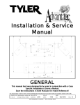
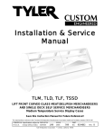
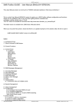
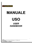
Installation & Service
Manual
GENERAL (UL/NSF)
This manual has been designed to be used in conjunction with a
Case Specific Installation & Service Manual.
Save the Instructions in Both Manuals for Future Reference!!
This merchandiser conforms to the UL Underwriter’s Laboratory, American National Standard Institute & NSF International Health and
Sanitation standard ANSI/NSF 7 - 2003. TYLER merchandisers and/or components are patented.
PRINTED IN Specifications subject to REPLACES
IN U.S.A.
change without notice. EDITION
10/04
ISSUE
DATE
4/07
Tyler Refrigeration * Niles, Michigan 49120
PART
NO.
9043544
REV.
C.1
GENERAL (UL/NSF)
CONTENTS
Page
Specifications
Line Sizing Requirements . . . . . . . . . . . . . . . . . . . . . . . . . . . . . . . . . . . G-3
Gas Defrost Liquid Lines . . . . . . . . . . . . . . . . . . . . . . . . . . . . . . . . . . . . G-4
Pre-installation Responsibilites
Shipping Inspections . . . . . . . . . . . . . . . . . . . . . . . . . . . . . . . . . . . . . . G-6
UL & ANSI/NSF Approval . . . . . . . . . . . . . . . . . . . . . . . . . . . . . . . . . . . . G-6
Pre-Installation Check List . . . . . . . . . . . . . . . . . . . . . . . . . . . . . . . . . . G-7
Installation Procedures
Carpentry Procedures . . . . . . . . . . . . . . . . . . . . . . . . . . . . . . . . . . . . . . G-7
Case Line-Up . . . G-7
Trim Installation, Alignment and Case Sealing . . . . . . . . . . . . . . . . . . . G-10
Plumbing Procedures . . . . . . . . . . . . . . . . . . . . . . . . . . . . . . . . . . . . . . G-14
Recommended Drain Practices . . . . . . . . . . . . . . . . . . . . . . . . . . . . . . . G-14
Refrigeration Procedures . . . . . . . . . . . . . . . . . . . . . . . . . . . . . . . . . . . G-15
Refrigeration System . . . . . . . . . . . . . . . . . . . . . . . . . . . . . . . . . . . . . . . G-15
Control Options . . . . . . . . . . . . . . . . . . . . . . . . . . . . . . . . . . . . . . . . . . . G-16
Setting the Superheat . . . . . . . . . . . . . . . . . . . . . . . . . . . . . . . . . . . . . . . G-16
Temperature-Pressure Chart . . . . . . . . . . . . . . . . . . . . . . . . . . . . . . . . . G-17
Defrost Information . . . . . . . . . . . . . . . . . . . . . . . . . . . . . . . . . . . . . . . . G-19
Off Time Defrost . . . . . . . . . . . . . . . . . . . . . . . . . . . . . . . . . . . . . . . . . . G-19
Optional Electric Defrost . . . . . . . . . . . . . . . . . . . . . . . . . . . . . . . . . . . . . G-19
Optional Gas Defrost . . . . . . . . . . . . . . . . . . . . . . . . . . . . . . . . . . . . . . . G-20
Optional Air Defrost . . . . . . . . . . . . . . . . . . . . . . . . . . . . . . . . . . . . . . . . G-20
Installation Procedure Check Lists . . . . . . . . . . . . . . . . . . . . . . . . . . G-21
Use of Case Alignment Clamps . . . . . . . . . . . . . . . . . . . . . . . . . . . . . G-22
Cleaning and Sanitation
General Cleaning Information . . . . . . . . . . . . . . . . . . . . . . . . . . . . . . . G-23
Case Cleaning . . . . . . . . . . . . . . . . . . . . . . . . . . . . . . . . . . . . . . . . . . . G-24
High Pressure Cleaning . . . . . . . . . . . . . . . . . . . . . . . . . . . . . . . . . . . . G-24
Cleaning Under Case with Base Rails . . . . . . . . . . . . . . . . . . . . . . . . G-25
General Information
Proper Case Usage . . . . . . . . . . . . . . . . . . . . . . . . . . . . . . . . . . . . . . . G-25
Shelf Light Sockets . . . . . . . . . . . . . . . . . . . . . . . . . . . . . . . . . . . . . . . G-25
Shelving Loads
. . . . . . . . . . . . . . . . . . . . . . . . . . . . . . . . . . . . . . . . . G-25
Service Instructions
Preventive Maintenance . . . . . . . . . . . . . . . . . . . . . . . . . . . . . . . . . . . . G-26
800MA T-12 Lamp Replacement . . . . . . . . . . . . . . . . . . . . . . . . . . . . . G-26
T-8 Lamp Replacement . . . . . . . . . . . . . . . . . . . . . . . . . . . . . . . . . . . . . G-26
Remote Ballast Replacement . . . . . . . . . . . . . . . . . . . . . . . . . . . . . . . G-27
Fan Blade and Motor Replacement . . . . . . . . . . . . . . . . . . . . . . . . . . G-28
Color Band and Bumper Replacement . . . . . . . . . . . . . . . . . . . . . . . G-28
Raceway Cover Removal . . . . . . . . . . . . . . . . . . . . . . . . . . . . . . . . . . . G-30
Kickplate Removal . . . . . . . . . . . . . . . . . . . . . . . . . . . . . . . . . . . . . . . . G-30
Front Kickplate or End Close-off Removal . . . . . . . . . . . . . . . . . . . . G-31
TYLER Warranty . . . . . . . . . . . . . . . . . . . . . . . . . . . . . . . . . . . . . . . . . . . . . . . G-32
Revision Log
Page G-2
. . . . . . . . . . . . . . . . . . . . . . . . . . . . . . . . . . . . . . . . . . .G-33
April, 2007
Installation & Service Manual
GENERAL (UL/NSF)
SPECIFICATIONS
CAUTION
Exposure to direct
sunlight in over 80°F
ambient temperatures
can cause permanent
damage to the vinyl
materials. If exposure to direct sunlight
is anticipated, loosely
cover the cases with
white canvas or plastic. This blocks
direct sunlight and
allows air movement
over vinyl parts.
TYLER will not be held responsible for
damage due to improper storage.
Line Sizing Requirements
CAUTION
Low temperature suction lines and all
liquid lines must be insulated in all
applications where subcooling (NC) is
used! This prevents line damage and possible product damage caused by freezing.
NOTE
Liquid and suction line lengths over 300
equivalent feet are discouraged by TYLER.
Contact applications engineering for recommendations on applications exceeding
300 equivalent feet!
HORIZONTAL SUCTION LINES SHOULD
SLOPE 1/2” PER 10’ TOWARD THE
COMPRESSOR TO AID IN GOOD OIL
RETURN!
Suction Line Sizing
The line sizing charts on each case specification sheet, shown above, can be used to size
the sub-feed branch lines. When the line
serves one case, select the size specified for
the 6’, 8’ or 12’ case. This may be as small
as 5/8” (example service meat cases), or as
large as 1-3/8” (example multi-shelf ice cream
cases). Select each suceeding step on the
basis of the number of feet of case being
October, 2004
ART 2
Revise line-up dimension art.
served by that portion of the suction line. For
more detailed Suction Line Sizing Charts, see
“Suction & Liquid Line Sizing” (BUFF) section
on the “TYLER Specification Guide”.
Liquid Line Sizing
Due to lack of space, the specification sheets
have just one column for a liquid line size.
The line sizes on the specification sheets are
based on a 5 pound pressure drop for the
entire piping run, from 50’ to 250’.
Example:
A 25,000 BTUH load
will require a 3/8” line
for 100 equivalent feet
(Point A). At 150 equivalent feet, a 1/2” line
would be required for
the same load (Point B).
For more specific line
sizing information, see
“Suction & Liquid Line
Sizing”(BUFF) section in
the “TYLER Specification
Guide”.
Page G-3
GENERAL (UL/NSF)
Header along cases - 7/8”
Line into cases are always 1/2”
Note: Tees point down
Main liquid line must be 5/8” minimum (even with just 1 case)
Gas Defrost Liquid Lines
3’ Max. for gas defrost
Gas defrost liquid lines to the cases should
be branched off the bottom of the header.
This ensures a full column of liquid to the
expansion valve. A branch line from the
header to an individual case should not be
over 3’ long and must have a 3” expansion
loop incorporated.
-100°F to -40°F = 2.5” per 100 foot run
(ultra low temp)
Do not run suction or liquid lines through
cases that are part of a separate system,
especially if either has gas defrost. If there is
no way to avoid this, insulate the piping for
the portion that runs through the other cases.
30°F to 50°F = 1” per 100 foot run
(high temp)
Temperature variations of refrigeration and
defrost cycles cause piping to expand and
contract. Allowing for this expansion and
contraction will prevent piping failures. The
following are typical expansion rates for
copper tubing;
Page G-4
-40°F to 0°F = 2” per 100 foot run
(low temp)
0°F to 30°F = 1.5” per 100 foot run
(medium temp)
Expansion loops are designed to provide a
definite amount of travel. Placing the loop
in the middle of a piping run will allow for
maximum pipe expansion with the minimal
amount of stress on the loop. Don’t use 45
degree elbows for loop construction because
they will not allow the lines to flex. Refer to
the charts on the next page for expansion
loop lengths. Suction and liquid lines cannot
be joined together or be allowed to touch.
Pipe hangers must not restrict the expansion
and contraction of piping. Insulation on
suction and liquid lines makes the whole
system more efficient! Insulate - it pays!
April, 2007
Installation & Service Manual
Expansion Loop Sizing
Chart 1 is to be used for A, B, and C type
expansion loops. Chart 2 gives the total
length of the expansion joint (L) along the
outer surface.
Example: Given a 200’ run of 1 3/8” medium
temp piping; there will be a linear expansion
Type “A” Loop
GENERAL (UL/NSF)
of 3” to compensate for (medium temp 1.5”
per 100’). Pipe diameter has no affect on the
amount of linear expansion but is needed for
determining the size of the expansion loop.
Find the 3” column at the top of Chart 1 and
go down until it crosses the 1 3/8” row. The
X dimension is 24”, 48”, or 72” for A, B, or C
type expansion loop respectively.
Type “C” Loop
Type “B” Loop
Tube
O.D.
‘X’ Length - (in inches) for Linear Expansion of:
Tube
O.D.
‘L’ Developed Length of Expansion Offsets
October, 2004
Page G-5
GENERAL (UL/NSF)
PRE-INSTALLATION RESPONSIBILITIES
Shipping Inspections
Shipping Damage
stated. Refer to “Liquid and Suction Line
Sizing Information” section in this manual for
TYLER’s requirements.
All equipment should be thoroughly examined
for shipping damage before and during
unloading.
This equipment has been carefully inspected
at our factory and the carrier has assumed
responsibility for the safe arrival of our product. If damage is concealed or apparent,
a claim must be made to the carrier.
Apparent Loss or Damage
Obvious loss or damage must be noted
immediately on the freight bill or express
receipt and signed by the carrier’s agent. If
this is not done, the carrier may refuse the
claim. The carrier will supply the necessary
claim forms.
Concealed Loss or Damage
When the loss or damage is not apparent
until after the equipment has been uncrated, a
claim for concealed damage must be filed.
Upon discovering the damage, make request
in writing to the carrier for inspection within 15
days and retain all packing. The carrier will
supply the inspection report and required
claim forms.
Application Recommendations
These cases are designed and built to be
used in properly air conditioned stores that
maintain a store temperature at or below 75F
(dry bulb) and a 55% relative humidity. These
cases may not operate satisfactorily at higher
temperature and humidity conditions.
Temperature performance is important for
controlling bacteria growth. The installer is
responsible for following these instructions as
set forth within this Installation and Service
Manual. Any variance will produce poor
performance, thus releasing TYLER
Refrigeration from any liability.
Refrigeration piping must be sized as
described within this manual by the installer.
Normal applications require refrigeration
piping to be insulated unless otherwise
Page G-6
One of these labels will be displayed on each
product, or as part of the bottom portion of the
namelplate label. NOTE: The NSF label
began with service case production.
TYLER Refrigeration of Niles, Michigan meets
UL and NSF International certification requirements. NSF certification is accredited by
American National Standards Institute (ANSI)
and the Standards Council of Canada (SCC).
Manufactured products are built to meet UL
requirements which includethe ANSI/NSF 7
standards for Commercial Refrigerators and
Storage Freezers. These standards provide
basic criteria to promote sanitation and protection of public health in the manufacturing,
operation and cleanability of TYLER cases.
All cases will be grouped in one of these categories; TYPE I display refrigerators where
ambient temperatures are typically maintained
at 75°F of less. Storage and display intended
for packaged products only. TYPE II display
refrigerators for ambient temperatures typically
maintained at 80°F or less. Display refrigerators intended for storage and display of NONHAZARDOUS FOODS consisting of unprocessed produce and packaged products only.
The information contained herein is based on
technical data and tests which we believe to
be reliable and is intended for use by persons
having technical skill, at their own discretion
and risk. Since conditions of use are outside
TYLER’s control, we can assume no liability for
results obtained or damages incurred through
the applications of the data presented.
SPECIFICATIONS ARE SUBJECT TO CHANGE
WITHOUT NOTICE. Printed in the U.S.A.
September, 2007
Installation & Service Manual
Pre-Installation Check List
WARNING
These cases are very heavy and require two
or more people to unload, move, position
and/or install them. Improper handling of
these cases could result in personal injury.
NOTE
Cases with legs are shipped to stores on
castors installed on the base frame. If floor
transition from the truck to the delivery dock
is smooth, cases may be rolled directly to
the sales floor area. If not, castors should
be removed in the truck and cases should
be unloaded and moved by one of the
conventional methods.
All cases containing glass MUST be stored and
installed on level surfaces to avoid possible
product damage and/or glass breakage.
1. Check for hidden damage while unloading
and unpacking of the case.
2. Check the “shipped loose” parts for any
items; such as legs, shelves, nuts and bolts,
caulking, access doors, etc.
GENERAL (UL/NSF)
INSTALLATION PROCEDURES
Carpentry Procedures
Case Line-Up
Before starting the case line-up, review the
store layout floorplans and survey the areas
where case line-ups are going to be installed.
WARNING
• These cases are very heavy and require
two or more people to move, position
and/or install them.
• Do not walk on the tops of these cases.
Tops of cases are not designed to support
the weight of a human being.
Improper handling of these cases could
result in personal injury.
NOTE
Allow at least 3” of air space between the
back of these cases and store walls or other
cases to minimize possible condensation
problems. Forced ventilation might be
necessary in some situations.
3. Check the equipment - remove the screws
used to hold down the deck pans during
shipping. Remove the pans and check the
following, if applicable:
4. Remove all packing material.
5. Check all flare nut connections for tightness.
6. Check all fan bracket bolts for tightness.
7. Check all electrical plug-in connections for
positive seal.
8. Make sure the expansion valve feeler bulb is
securely attached to the suction line.
9. All field wiring and plumbing MUST conform
to national, state, and local codes.
10. Do not remove plugs (from flare nuts) or
caps (from threaded connections) until the
unit is ready for final hook-up. All coils are
pressurized and have a Schrader Valve
access fitting. If pressure has been lost,
check for leaks.
October, 2004
1. Snap chalk lines where the front and rear
legs and/or base rails of the cases are to be
located for the entire line-up.
Page G-7
GENERAL (UL/NSF)
NOTE
Front and rear edges of legs and/or base
rails should always be used to line-up
cases. Cases with legs have built-in leveling adjustment capabilities. Cases with
base rails use 6” shims that allow adjoining ends of cases to be shimmed together.
2. Cases with legs are shipped on pallets
with the legs in an attached shipping
package. Position case approximately
where it is going to be installed.
Carefully lift case off skid, with a proper
lifting device, and install legs into the
threaded holes in the base. Make sure
all legs are completely threaded into the
base to properly secure them. Thread
out bottom leg insert, up to 1 1/2”, to
level the case.
If case has base rails, locate highest
point on chalk lines as a reference for
determining the number of shims to be
placed under the case base rails. Position
first case at highest point on the chalk
lines and shim case supports as required.
CAULKING
3. Apply two heavy beads of caulking
compound from the Filler Kit to the end
of case at dotted (. . .) and dashed (- - -)
lines. Proper caulking provides good
case refrigeration and sanitation.
Check leveling at hand rails, top of case,
and back of case.
CAUTION
Shipping braces should only be removed
from case ends that are to be joined. This
protects the cases from possible damage
during the line-up procedure.
NOTE
A foam gasket is factory installed on one
end of the case. This gasket fits into a
groove on the adjoining case when cases
are pulled together. Do not depend on the
foam gasket alone to make a good seal!
Page G-8
4. On multi-shelf cases, remove bottom tray
(1), front duct (2) and rear and/or top
pull-up access covers (3).
October, 2007
Installation & Service Manual
On single deck cases, remove bottom
tray (1), front duct (2) and rear pull-up
access cover (3).
GENERAL (UL/NSF)
On NNG, N3MG, N2P(S) cases, remove
bottom tray (1), front cladding (4), and/or
rear pull-up access cover (3).
On cases with legs, pull-ups are accessible
under and behind the case corners.
5. The remaining backers and hardware are
in a plastic bag taped to the interior of the
case.
6. Push cases tightly together making sure
the pull-ups are aligned.
On waterfall produce cases, remove
bottom tray (1) and access covers (3).
On island cases, remove front and rear
pull-up access covers (3).
October, 2004
Page G-9
GENERAL (UL/NSF)
7. Adjust legs (not shown) or add shims (5),
as required, under the adjoining case
base rails (6). Check leveling at hand
rails (7), top of case (8), and back of case
(9). NOTE: Shelving bracket slots
must be aligned. Use recommended
case alignment clamps to help
installation. See page G-22.
CAUTION
Do not drill or use other holes through the
case end for pull-ups. This may deform
the case end and could cause joint leaks
and/or poor refrigeration.
8. Position all pull-up bolts and/or mounting
hardware (10) at pull-up locations (A and
B), (A, B and C) or (A, B, C, and D). Do
not tighten any pull-up hardware until all
of it has been installed. Tighten all pull-up
hardware equally starting at point A and
finishing at point D. Do not overtighten.
Page G-10
9. Install all pull-up access covers (3), front
duct (2), bottom tray (1) and/or front
cladding (4), where applicable.
10. Remove shipping tape from all
fluorescent lamps.
Trim Installation/Alignment
Upper Trim Installation
Loosen screws as needed to line-up the
canopy hoods. Hoods are adjustable in all
directions.
1. Position canopy joint trim (1) over any
gap between the canopy hood joint (2).
Secure canopy joint trim (1) with screws
at top and bottom as shown.
2. Install top pull-up access cover (3) to
cases (4) with four screws (5).
April, 2007
Installation & Service Manual
Horizontal Joint Trim Installation
GENERAL (UL/NSF)
NOTE
Make sure top of front glass is aligned
be- fore installing the front glass trim.
1. Apply bead of caulking compound from
the Filler Kit to the top of each horizontal
joint (1). If gap at horizontal joint is too
large, pull together with sheet metal
screws (2) or pop-rivets (3).
NOTE
If additional sealing is preferred, 2” wide
duct tape can be applied to the top of the
internal bottom joint between cases. The
tape will be covered by the horizontal joint
trim. Duct tape is not furnished.
1. Position front glass trim (1) over the top
and in front of the glass joint (2).
2. Using holes in front glass trim (1) as a
guide, drill holes in front glass retainer (3).
3. Secure front glass trim (1) with two
screws (4).
Bumper and Color Band Adjustment
1. Slide hand rail/bumper retainer (1) and
bumper (2) towards the center of the lineup to butt them against the adjoining hand
rail/bumper retainer (1) and bumper (2).
2. Apply sealer to horizontal joint trim (4)
and install joint trim (4) on the horizontal
joint (1).
Front Glass Trim Installation
The following instructions can be used to
install the front glass trim on cases with 6” or
12” front glass.
October, 2004
2. Position hand rail backer (3) to cover any
remaining space between the adjoining
hand rail/bumper retainers (1).
NOTE
Color band backers on glass front cases
are installed by sliding the band toward
open end, inserting the backer at the case
joint and sliding the band back over the
backer. Installation of backer at last joint
in a line-up requires bumper and bumper
retainer removal on the end case.
Page G-11
GENERAL (UL/NSF)
Raceway Cover Installation
NOTE
Raceway covers are shipped loose.
They should not be installed until all case
piping and electrical hook-ups are
complete.
3. To adjust a bumper backer (4): remove
bottom of both bumpers (2) at the joint;
reposition the bumper backer (4) behind
the joint; snap bumpers (2) back in place.
Make sure color band backer is centered
behind any exposed color band joints.
1. Position top of raceway cover (1) in
bottom of lower cladding (2).
2. Center the raceway backer (3) behind
joint of adjoining raceway covers (1).
3. Rotate raceway cover (1) down and
position retainer plates (4) with screws
(5). Slide all raceway covers (1) toward
center of case line-up then tighten
retainer plate screws (5).
4. After all bumpers (2) in a case line-up
have been pushed together towards the
center, snap on and position bumper end
trim (6) so it covers any end gap between
the end of the bumper and the patch end.
4. After raceway covers have been slid
together towards center of case line-up
and secured, install top of raceway end
trim (6) in lower cladding (2) and secure
bottom with screw (7).
Page G-12
April, 2007
Installation & Service Manual
GENERAL (UL/NSF)
Kickplate and End Closeoff Installation
(High & Low Base Models without Legs)
NOTE
• Seal the front base rail to the floor
before installing kickplate supports.
• Kickplate supports MUST be installed
before piping case.
• Kickplate and end closeoff should not
be installed until all case piping and
electrical hook-ups are complete.
3. Install metal kickplate (4) onto kickplate
supports (1 or 2) and secure with screws.
4. Install kickplate joint trim (6) over each
metal kickplate joint in the lineup and
secure with screws.
1. Using Dow-Corning 732, 737, 999A or
equivalent NSF silicone adhesive (not
supplied), completely seal bottom front
edge of front baserail to floor. This
includes any gaps made from the shims
used for leveling the case lineup.
Correctly applied silicone must fill the gap
between the base rail and the floor and
completely contact both the front base rail
and the floor.
5. Install the lower end closeoff (7) between
bottom of patch end and case base rail
and secure with screws. The flanged end
of the closeoff (7) should cover the end of
the metal kickplate (4).
6. Seal bottom edge of lower end closeoff
(7) to floor using Dow-Corning 732, 737,
999A or equivalent NSF silicone adhesive
(not supplied).
NOTE
Sealing base rails and end closeoffs will
keep floor spills from running under case
lineups.
2. Position slots of kickplate support
assemblies (1) or kickplate support (2)
over premounted base rail shoulder
screws (3). Push kickplate supports (1 or
2) down until they are flush with the floor.
October, 2004
Page G-13
GENERAL (UL/NSF)
Front, Rear and End Closeoff Installation
(High Base Models with Legs)
NOTE
Closeoffs should not be installed until all
case piping and electrical hook-ups are
complete.
Both the front and rear closeoff
assemblies install the same way.
Plumbing Procedures
Recommended Drain Practices
CAUTION
A clogged waste outlet blocks refrigeration.
This could result in inadequate case
cooling and possible food spoilage.
The installer is responsible for the proper and
code approved installation of a system which
dispenses condensate waste water through
an air gap into the building’s indirect waste
system.
Waste outlets and drip pipes from refrigerators
are not intended for direct connection to the
building plumbing system. All remote
refrigerators equipped with automatic or off
time defrost systems are provided with a
waste outlet. The outlet is located in the
lowest level of the compartment to which
waste water will drain.
1. Position front or rear closeoff assembly (1
or 2) so bottom edge is flush with the
floor. Push in closeoff assembly (1 or 2)
at each case leg locations until the closeoff brackets (3) snaps onto each leg (4).
All TYLER display refrigerators are provided
with a water seal. It may be factory installed
or shipped loose for field installation. If
shipped loose, the installer must follow
TYLER’s installation procedure as outlined
within this manual.
The importance of proper drain connections
cannot be overemphasizes. Complications
resulting from drainage problems can be
avoided by following these good drainage
guidelines.
2. Install the end closeoff (5) between
bottom of patch end and case frame.
The flanged end of the end closeoff (5)
should cover both the ends of the front
and rear closeoff assemblies (1 & 2).
Page G-14
1. The minimum slope of waste pipe should
be 1/4” per foot, or more if possible.
April, 2007
Installation & Service Manual
2. The maximum length of waste pipe
should not exceed 12 feet.
3. Never downsize the drain lines. Lines
should be at least the same diameter as
the trap.
GENERAL (UL/NSF)
Refrigeration Procedures
Refrigeration System
CAUTION
• Protect Schrader valve core and cap and
the expansion valve feeler bulb from
excessive heat by removing them when
necessary. Replace properly before
starting the system.
• Brazing and welding operations should
be kept away from both the drain pan
and sealing materials in the drain area.
High temperature exposure in these
areas may cause damage to seals and/or
painted surfaces of the drain pans.
4. On low temp cases, the trap must be
away from the tee to prevent possible
freezing of the trap.
The type of refrigerant used in the case will be
specified on the unit nameplate. A Schrader
valve is provided at the left of each coil for
system testing and charging.
The suction and liquid lines to the evaporator
coils are capped off. This holds the dry
nitrogen charge inside the evaporator coils.
When cutting off the caps, use a tubing cutter
to prevent the introduction of copper
shavings to the system. See the model
specification sheet in the case specific I&S
manual for proper line entry and positioning
specifications.
5. Up to two case drains can utilize one floor
drain. NOTE: Both case drains require
individual water seals.
Only use clean, dry, sealed refrigeration grade
copper tubing. Make copper to copper joints
with phos-copper alloy (5% silver) or equal.
Make dissimilar metal joints with solder having
35% silver. To prevent internal contamination
of the line, limit the use of soldering paste or
flux to the minimum required. Flux only the
male portion of the connection.
Piping should be purged with dry nitrogen or
carbon dioxide during brazing. This prevents
the formation of copper dioxide and scale
during brazing. Copper dioxide and/or scale
can easily clog the small ports in system
valves and pilot valve.
6. Never put two case drains with two traps
on the same waste pipe. This can cause
an air trap on one of the case drains.
October, 2004
Page G-15
GENERAL (UL/NSF)
NOTE
The tubing design pressure is 183 psig for
the lowside and 390 psig for the highside.
Do not exceed these pressures.
Line Entry
Refrigeration lines entry may only require a
single entry for an entire line-up of cases. It
could enter the line-up at one end or branch
both ways from the center. Refrigeration lines
may be run from case to case in areas
designated for them. Notches are provided
in both ends for this purpose.
Line sizing should meet the suction and liquid
sizing requirements for that case location in
the line-up. See “Line Sizing” section in this
manual. If the cases are connected to a
parallel system, the line size will be specified
on the system printout.
CAUTION
Do not run tubing through these cases
to another machine if the cases are
controlled by a pressure control. Pressure
sensed from the coldest location could
affect the pressure control in a second
system. This is called cross-controlling
and should be avoided.
A pressure drop in the suction line means a
loss in system capacity. It forces the
compressor to operate at a lower suction to
maintain the desired temperature in the
evaporator coil. Pressure drops reduce
compressor capacity and increase system
compression ratios causing higher operating
costs. To minimize pressure drop, keep the
refrigeration line run as short as possible and
the number of fittings to a minimum.
All suction lines should be insulated to
minimize heat absorption and condensation
drippage. Seal refrigeration lines where they
enter the case. Sealing is necessary to
prevent condensation, air leaks and other
problems. Be sure it is done before leaving
the job.
Page G-16
NOTE
It is very important to have a good seal
around the refrigeration lines. This will
prevent any water leakage into the bottom
of the case. During the installation
process do not disturb the factory seal
between the drain and case ends. This
seal must remain water tight. The access
opening should be insulated along with
all refrigeration lines exiting the case to
prevent condensation buildup on cold
surfaces.
Control Options
The temperature of case line-ups can be
controlled by one of the following methods:*
1. Indoor single compressor system not
using a liquid pump down before defrost.
The low pressure control on the
compressor system can be set to cycle
the compressor on and off at specific
pressures that correspond to the desired
temperature range at the case.
2. Indoor single compressor system needing
a more accurate temperature control. A
thermostat can be mounted with its
sensing bulb in the discharge air stream
on the case. The thermostat is used to
cycle the compressor on and off at
specific temperature to maintain the
desired case temperature range.
3. Outdoor single compressor system using
a liquid pump down cycle before defrost,
or other applications that need a more
accurate temperature control. A thermostat can be mounted with its sensing bulb
in the discharge air stream on the case.
The thermostat is used to cycle a main
liquid line solenoid valve on and off at
specific temperatures to maintain the
desired case temperature range. The
liquid line solenoid valve used for
temperature control should be mounted
as close to the case as possible to
minimize the temperature swing that may
occur after the valve closes.
April, 2007
Installation & Service Manual
4. Parallel compressor system, or other
applications needing a more accurate
temperature control. An evaporator
pressure regulator (EPR) valve is installed
between the case and the compressor.
The EPR valve is set to control the case
suction pressure which corresponds to
the desired case temperature. The EPR
valve will hold a relative constant pressure
at the case and will not allow it to go
below a set pressure.
*See model specification sheet in the case
specific I&S manual for specific control
settings for each case.
Setting the Superheat
Use the instructions, illustration, and chart
below to determine the superheat.
NOTE: This illustration shows the general
location of piping and components in a
case with two expansion valves.
1. Make sure all connections to the
expansion valve(s) are tight.
2. If a case has more than one expansion
valve, starve the flow to the front coil’s
expansion valve by turning in the
adjusting screw 1 1/2 turns.
NOTE: Rear coil expansion valve should
always be adjusted first.
3. Install pressure gauge on the coil output.
Most TYLER cases have a Schrader fitting
for this purpose. Record the pressure
reading.
March, 2006
GENERAL (UL/NSF)
4. Using the table on the following page,
convert this pressure to a temperature.
5. Take a temperature reading from the
suction line adjacent to the expansion
valve bulb being tested.
6. Subtract the temperature conversion
(step 4) from the suction line temperature
(step 5). This is the superheat of the
evaporator.
7. If case has more than one expansion
valve, reset front coil expansion valve by
repeating steps 2 thru 5.
See next page for adjustment settings for
Sporlan and Alco Expansion Valves.
Balanced Port Expansion Valves used in
TYLER cases are preset by an air pressure
bench test. Some final adjustment may be
necessary due to system designs, pressure
drops, and coil loading. Adjustments should
be made with liquid pressures near design,
and after the case has been loaded and
pulled down to normal temperature
requirements. Final adjustments are used to
maximize case temperature and efficiency.
There is no magic superheat number. Proper
settings can actually occur from as low as 4
or 5°F up to extremes of 17 or 18°F of
superheat. Most settings will fall in the 6 to
12°F range. All high performance case
settings should fall in the 4 to 6°F range. A
proper method is to find a setting within the
ranges previously mentioned that provides
the most stable bulb temperature.
Sometimes there will be a flat reading with virtually no variation. This usually provides the
lowest discharge air temperature reading.
Proper expansion valve settings cannot be
made in a few minutes. Only turns of 1/4 to
1/2 should be made at one time. Wait 15
minutes to allow the system to settle out.
Please refer to comments below regarding
the differences in adjustment between
Sporlan and Alco expansion valves.
Page G-17
GENERAL (UL/NSF)
CAUTION
Forcing the adjustment beyond the stops
will result in damage to the valve.
NOTE
All of the following changes are
approximate and should only be used
as a guideline!
TEMPERATURE-PRESSURE CHART
SPORLAN VALVES:
The number of adjustment turns available
between stops on the Sporlan valves is 9 to
10 turns (in or out).
• With R-22 refrigerant, 1 turn will result in
approximately a 5.5 or 3°F superheat
change for low or medium temperature
applications respectively.
• With R404A refrigerant, 1 turn will result in
approximately a 4.5 or 2.5°F superheat
change for low or medium temperature
applications respectively.
• With R-502 refrigerant, 1 turn will result in
approximately a 5 or 2.5°F superheat
change for low or medium temperature
applications respectively.
• With R-507 refrigerant, 1 turn will result in
approximately a 4.5 or 2.5°F superheat
change for low or medium temperature
applications respectively.
Page G-18
ALCO VALVES:
The number of adjustment turns available
between stops on the Alco valves is 10 to 12
turns (in or out).
• With R-22 refrigerant, 1 turn will result in
approximately a 4.5 or 2°F superheat
change for low or medium temperature
applications respectively.
• With R404A refrigerant, 1 turn will result in
approximately a 3.5 or 1.5°F superheat
change for low or medium temperature
applications respectively.
• With R-502 refrigerant, 1 turn will result in
approximately a 3.5 or 1.5°F superheat
change for low or medium temperature
applications respectively.
• With R-507 refrigerant, 1 turn will result in
approximately a 3.5 or 1.5°F superheat
change for low or medium temperature
applications respectively.
April, 2007
Installation & Service Manual
Defrost Information
NOTE
See Case Specific I&S manual for individual
defrost settings and klixon locations.
Off Time Defrost
All cases that use a refrigerated coil that
operates below the freezing point of water will
collect frost during the refrigeration cycle. Too
much frost build-up on the cooling coil stops
the effective air flow and refrigeration. An off
time control stops the refrigerant and allows
the case to defrost at the proper time and
duration each day.
The refrigeration is stopped with a time clock
(mechanical or electronic) by either turning off
the compressor directly, or closing a liquid line
solenoid or suction isolation valve (ex. suction
line solenoid or suction stop EPR valve). The
time clock is set for the proper number of
defrosts per day and the proper duration per
October, 2004
GENERAL (UL/NSF)
defrost based on the information provided
under “Specifications” in the case specific
manual. The time clock may be an individual
clock on single compressor system; a
multi-circuit clock on parallel compressor
system; or an electronic clock on either
compressor system.
Optional Electric Defrost
When an electric defrost is initiated, power is
supplied to the defrost heater. The defrost
heater is located in front of the coil. The
defrost heater will be turned off or deenergized when the defrost limit klixon
clipped to the right end of the coil, opens at
its specified temperature.
Balanced 3-Phase Defrost Wiring
The largest number from any of the following
will be the highest load on any single phase.
This is called the high leg amps. In the
following example a TG-3-30 defrost module
is required.
Page G-19
GENERAL (UL/NSF)
L1 = All Loads on leg 1 x 1.73
2
activate and deactivate the drain pan heater
as needed during the defrost cycle.
L2 = All loads on leg 2 x 1.73
2
L3 = All loads on leg 3 x 1.73
2
13.8
13.8
8.6
8.6
Optional Air Defrost
EXAMPLE:
L1 = 13.8 + 8.6 + 8.6 x 1.73 = 26.8 amps
2
L2 = 13.8 + 13.8 x 1.73
2
= 23.9 amps
L3 = 13.8 + 8.6 + 8.6 x 1.73 = 26.8 amps
2
In this case the high leg amps equals 26.8.
Optional Gas Defrost
When a gas defrost is initiated, the evaporator
acts as a heat exchanger for incoming liquid
during the refrigeration cycle and as a drain
pan heater during gas defrosting. A defrost
termination klixon is located at the bypass
check valve. When the defrost termination
klixon senses the appropriate temperature, it
shuts off the flow of hot gas. Most cases use
a 55° or 60°F defrost termination klixon that
will represent 70°F due to time lag. Use 70°F
termination setting for electronic temperature
sensors. On N6D deli cases, meat cases
and glass door cases , the fans are
deactivated during gas defrost by a fan delay
klixon located on the right end of the coil. Fan
operation will restart when the klixon senses
the appropriate temperature. On glass door
cases, there is an additional klixon used to
Page G-20
Most TYLER multi-shelf meat and deli
merchandisers can be equipped with air
defrost. Air defrost effectively defrosts with
comparable product quality to electric or gas
defrost, but costs less. The reversible
permanent split capacitor (PSC) fan motors
which make air defrost possible, cuts the cost
of fan operation considerably. The motor
design and the capacitor required for reversal
makes the motor much more efficient.
When an air defrost is initiated, fan operation
is reversed. This causes the fans to circulate
store air in place of refrigerated air supply. A
klixon (42°/32°) is located on the right end of
the coil. When all cases on that circuit have
reached 42°F, the defrost will be terminated
and the fans will switch back.
The purpose of the following arrangements
is to stop the flow of refrigerant through
the display so that it may defrost:
Single Condensing Unit
Liquid flow may be interrupted by a normally
closed liquid line solenoid valve (installed at
the compressor or case) controlled by a
thermostat and wired to the time clock. The
time clock would cause the solenoid to close,
this would in turn shut off the flow of liquid
refrigerant to the system(s). The compressor
April, 2007
Installation & Service Manual
would continue to run and pump down the
system(s). The condensing unit would soon
shut off on low pressure. The time clock may
also be wired directly to the compressor
contactor.
Parallel Compressor Unit
For cases operated from a parallel
compressor rack, an evaporator pressure
regulator (EPR) valve may be factory
installed on the suction stub of the parallel
compressor rack. The EPR valve will work in
conjunction with the defrost circuit(s). This is
temperature regulation (by pressure) of the
entire lineup. A solenoid may be used in
conjunction with the EPR valve to stop
refrigerant flow during defrost.
Installation Procedure Check Lists
Carpentry (Line-Up) Check List
1. Make sure there is a smooth transition
from the truck to the delivery dock before
rolling cases with casters off the truck.
NOTE
All necessary hardware and caulking can
be found in the Filler Kit located in the well
of each case.
2. Check the level of the floor area where
the cases are going to be lined up.
3. Set and level the first case at the highest
point on the floor.
NOTE
Adjacent cases may require different
amounts of levelling or shimming to allow
for proper case line-up.
4. Level cases as necessary (legs with
leveling inserts or shims) to align case
pull-ups, fronts, tops, and allow for
proper operation.
5. Have case to case joints been properly
caulked and sealed? Each joint requires
two beads of caulking where the cases
join together. One bead on the inside
and outside of the foam gasket and door
frame assures good sanitation and
refrigeration. See “Case Line-Up” in this
October, 2004
GENERAL (UL/NSF)
manual for proper caulking locations.
6. Have the patch ends been properly
caulked and installed with the proper
hardware?
7. For cases with shelves, make sure the
shelving bracket slots on multi-shelf cases
line-up and that the shelves are installed in
the proper position.
NOTE
The bumpers should all be pushed tight
against the center case in the line-up
before the end trims are installed.
8. After cases are completely installed and
where local sanitation codes mandate,
seal front bottom edge of front base rails
with Dow-Corning 732, 737, 999A or
equivalent NSF silicone adhesive (not
supplied).
9. Make sure all bumpers, front cladding,
raceway covers and kickplates or front
and rear closeoffs are properly installed
and secured. Install end trims and seal
bottom edge (if required) with NSF silicone adhesive (not supplied).
Plumbing Check List
1. All plumbing must conform to all national,
state and local codes.
NOTE
Be sure the drain is installed in accordance
with the following specifications and the
drain instructions in this manual.
2. The minimum slope should be 1/4” per
foot or more if possible.
3. The maximum length should not exceed
12 feet.
4. Never downsize the drain lines. Lines
should be at least the same diameter as
the trap.
CAUTION
Hooking two cases and traps into the same
drain line will cause an air trap in one of
the two cases. This will cause improper
drainage to the case with the air trap.
5. Two cases can utilize one floor drain as
long as both lines and traps are run
separately to that drian.
Page G-21
GENERAL (UL/NSF)
Electrical Check List
1. All field wiring must conform to national,
state and local codes.
2. Make sure all electrical connections are
properly connected and tight.
Refrigeration Check List
In addition to the standard practices which
should be used in the installation of this case,
the installer should pay particular attention to
the following items:
1. Has the refrigerant line entry been caulked
thoroughly?
2. Are all fans running? Are the fan electrical
connections tight?
NOTE
Proper settings and/or temperatures for
items 3, 4 and 5 can be found in the “Model
Specification Sheets” in the case specific
I&S manual or the “BUFF” section in the
Specification Guide.
temperature. Check for outside influences
that might affect the case performance.
(Example: Drafts from ventilator openings
or radiant heat from light fixtures that are
too close.)
Use of Case Alignment Clamps
1. Check and mark the floor where the cases
are to be set.
2. Set the first case in the line-up on the
highest point of the floor.
3. Level the first case end-to-end and front-toback using the legs or provided shims.
NOTE
On cases with base rails, 6” shims should be
placed beyond the end of the base rails so
the next case can be set on the same shims.
NOTE
Individual case
alignment clamps
are available
through TYLER
Service Parts
Department
under Part No.
5092494.
3. Is the defrost control set for correct
number of defrosts per day?
4. Is the failsafe set for the proper times?
5. Does the discharge air temperature match
the recommended temperature for this
case?
6. Is the suction pressure drop less than
2 PSIG from the last case to the
compressor? (Remote case only)
7. Are the expansion valve feeler bulbs
securely attached to the suction lines?
8. After final hook-up of the case, let it run
through a defrost cycle (preferably two or
more). Check the duration and frequency
of the defrost cycle for compliance to
specification data.
9. Check the operating temperature to be
sure the case is functioning within the
recommended guidelines.
10. Verify that the store temperature and
humidity levels are within the recommended guidelines. Use a wet and dry
bulb psychrometer to check the store
Page G-22
4. Set the next case in the line-up. Use two
alignment clamps on the horizontal joint in
the bottom of the cases. The clamp near
the front of the cases will line-up the hand
rails. The clamp near the back of the cases
will line-up the shelving bracket slots.
5. Level the case end-to-end and front-to-back,
by adjusting legs or shimming base rails.
6. Adjust the alignment clamps as needed to
allow for the installation of pull-up hardware.
NOTE
Do not remove alignment clamps until the
pull-up hardware has been tightened.
April, 2007
Installation & Service Manual
CLEANING AND SANITATION
General Cleaning Information
Equipment life and performance are directly
related to good cleaning and sanitation
practices. Recommended cleaning intervals
will vary depending on the case’s useage.
Cleaning cases, case parts and area around
cases regularly will keep high sanitation
levels, increase case life, and minimize
maintenance costs.
Most TYLER cases provide the following case
cleaning features to support good cleaning
and sanitation practices.
GENERAL (UL/NSF)
• Do not use liquid chlorine bleach or
products containing bleach on metal
surfaces. The corrosiveness of these
products will damage the metal and
void the case warranty.
Metal surfaces that are powder coated should
be cleaned daily with a damp cloth. After
initial installation, apply coat of appliance wax
to these surfaces. Repeat wax application as
necessary to keep surfaces shining.
Stainless steel surfaces should be cleaned as
needed with a damp soft cloth. In addition,
stainless steel cleaners may be used to help
protect surfaces longer.
• Removable screens, lower trays and front
& rear ducts.
• Fully accessible 1-1/2” or 2” waste outlets
on most cases.
• Hinged or easily removable fan panels and
coil & piping covers provide access to
lower coil and drain pan.
• Seamless, smooth drain pan is water-proof
and contoured for easy cleaning and rapid
drainage.
• Cases with pipe legs have removable front
and rear closeoffs to provide access to
area under cases for easy cleaning.
• Cases with base rails provide front or
side access for cleaning areas under
cases with dust mop or vacuum hose
with nozzle. (See page G-13 in this
manual for resealing of lower end
close-offs.)
Since cases are made up of different types of
materials, the care requirements change with
the material type and style.
Rigid vinyl surfaces (bumpers, handrails &
raceway covers) should be cleaned with a
soft cloth and warm soapy water, or with
non-abrasive cleaners like Fantastik or Pro
Formula 409 with a mildly abrasive sponge.
Both of these cleaners will do an excellent job
in most instances. Clean difficult spots with
Comet cleanser with chlorinal and a plastic
scrubber or abrasive sponge. Manufacturers
directions should be followed carefully.
CAUTION
Do not use hot water on cold glass
surfaces. This can cause the glass to
shatter and could result in personal injury.
Allow glass fronts, ends and service doors
to warm before applying hot water.
• Never use abrasive scouring pads
or cleansers on exterior or interior
surfaces. The abrasive materials
could scratch the surfaces.
• Do not use any ammonia based
cleaning products on any cases with
electronic and solid state components.
The ammonia will permanently damage
these components.
April, 2007
CAUTION
Do not use Comet on corner or vacuum
formed trim. Discoloration could occur.
Corner trim for island cases and vacuum
formed trim for wedge cases should be
cleaned only with Fantastik or Pro Formula
409.
Cleaned surfaces treated with Armour All
or Pledge furniture polish will help keep
surfaces looking good and make them easier
to clean.
WARNING
Exterior and interior glass surfaces, brushed
aluminum and chrome should be cleaned
with a lint-free cloth and warm water or glass
cleaner.
Page G-23
GENERAL (UL/NSF)
Remove normal accumulation of dirt and debri
daily to maintain efficient refrigeration. Interior
surfaces require different cleaning intervals.
Cases should be cleaned and sanitized per
Federal, State and Local Ordinances.
Typically, meat and produce cases should be
cleaned at least once a week; dairy cases
every two to four weeks; and frozen food cases
every two to six months. Interior surfaces may
be cleaned with most domestic detergents
and sanitizing solutions with no harm to the
surfaces.
Honeycombs or grids in the air ducts should
be checked and cleaned whenever the case
interior is cleaned. To clean a honeycomb or
grid, loosen the screws and slide retainer
back, or remove screws and retainer to remove
honeycomb or grid from the air ducts. Clean
the honeycomb or grid with copressed air,
vacuuming system, or spray detergent and
rinse. Make sure the honeycomb or grid is
dry before replacing it in the case. Reinstall
honeycomb or grid in air duct and secure with
retainer and screws.
Case Cleaning
All case cleaning is dependent on proper
installation of the cases with good caulking
between cases and adequate case drainage
system. Cleanout holes in bottom trays
facilitate case drainage.
NOTE
Consult a service agency for proper method
of shutting off the refrigeration and electrical
supply.
1. Shut off refrigeration supply to the case(s)
and electrical power to the case fans,
anti-sweat wires and internal lights.
2. Remove product from case and store in an
another case or walk-in facility.
3. Remove screens, trays, bottom pans, ducts
(where applicable) and all
removeable interior covers. Clean parts
separately as discribed on this page.
CAUTION
Do not soak lighted shelves! Water will
short or damage the shelf lighting system.
4. If case has lighted shelves, remove and
clean separately by wiping with a damp
Page G-24
cloth. Make sure receptacle covers are
installed when shelves are removed.
5. Remove all loose debris from the case. It
could clog the drain during cleaning.
NOTE
• If a germicidal detergent is not available,
rinse after cleaning and apply a sanitizer.
Sanitizer should thoroughly drain and
air dry.
• When cleaning and rinsing this case, try
not to use water faster then the case
drain can carry it away.
6. Clean surface with warm water and
germicidal detergent at recommended
concentration. A brush or cleaner pad will
aid in removing dirt. Don’t soak electrical
wiring and fans unnecessarily. Rinse
thoroughly with clean water and let air dry.
7. Sanitize the case with Quaternary
Ammonium Solutions (ex: KAYQUAT II,
J-512 Sanitizer, SANIQUAT 512, etc...)
approved per 21CFR 178.1010, followed by
adequate draining and air drying. These
solutions may be obtained from Kay
Chemical Co., Johnson Wax Professiona,l
Coastwide Laboratories, etc....
8. Replace all internal parts so that they seat
properly. This is necessary for proper case
operation.
WARNING
Never turn case electrical power on until all
components are dry! Reconnecting power
to case with wet components could cause
damage the case or personal injury.
9. Restart refrigeration supply to the case(s)
and electrical power to the case electrical
circuits.
10. Replace product after the case has reached
the proper operating temperature.
High Pressure Cleaning
If a high pressure cleaner is used for case
cleaning, the following cleaning precautions
must be taken to discreetly flush the case.
WARNING
Wear safety goggles while using high
pressure equipment. This equipment is
designed to operate at 500 psi pressure.
High pressure water and/or flying objects
April, 2007
Installation & Service Manual
could cause eye or other bodily injuries.
• Remove all loose and removable
electrical components before using high
pressure equipment.
• Do not use water over 160°F. Water too
hot will cook soil into place and obscure
the worker’s visability.
• Do not misuse high pressure spray
equipment by directing spray on any
electrical equipment such as fan motors
and light sockets.
• Do not direct high pressure spray at
case joints or glass joints. The seals
may not hold up to the high pressure.
GENERAL INFORMATION
Proper Case Usage
Display Practices
Do not let a flair for spectacular exceed the
refrigerating capacity of the cases. Mounds
of product over the load lines or large
signage cards interfere with case air flow.
Displays of products in multi-shelf cases
require rotation to prevent frost accumulation.
Jumble displays of cans should be avoided.
Uneven display surfaces cause extra air
turbulence that make heavier frost deposits
on the coils.
Stocking & Maintenance Practices for
Multi-Shelf Low Temperature Cases
A large volume of air is constantly in motion
in all makes of multi-shelf low temperature
cases. When the case is defrosted, air
temperature rises for the short time it takes
the case to defrost. The relatively warm air
causes frost to be deposited on the cold
products. Most frost is removed naturally,
shortly after the defrost cycle ends. However,
some frost may remain on the products
stored in the back of the case. Product
rotation is the moving of product from the
rear to the front and adding new stock to the
rear. This prevents frost from accumulation
on products stored in the rear of the case.
NOTE
Frozen foods are perishable and cannot
be left on display indefinitely.
October, 2007
GENERAL (UL/NSF)
Clean multi-shelf cases regularly.
Removing loose bits of wrappers or other
debris daily, prevents the need for shutting
down the case for major cleaning. Keeping
drain clogging litter out of the case is very
important in preventing refrigeration failure or
sub-par performance.
Shelf Light Sockets
Both types of shelf light plug sockets allow for
shelf positioning. One shelf light socket is vertically adjustable. It moves up or down to clear
back edge of shelf for electrical connection.
Remove top screw stop to completely remove
this shelf light socket assembly.
The second shelf light socket is stationary, but
allows the plug to be installed right side up or
upside down to accommeodate the shelf position. Remove top and bottom retainer pins to
remove the second shelf light socket assembly.
CAUTION
Make sure the shelf light plugs or receptacle
covers are completely inserted into the light
socket receptacles. This prevents electrical
arcing and/or possible equipment damage .
Shelving Loads
Case shelves are
designed to hold approx.
40 lbs per sq. ft. NOTE:
Slots in the shelf brackets engage in the back
of the shelves when the
brackets are in a down position. This provides
additional shelf support.
Shelf Load Chart
Shelf
Size (in)
12 x 48
15 X 48
18 X 48
20 X 48
22 X 48
Shelf Area
(Sq. Ft.)
4
5
6
6.7
7.3
Maximum
Shelf Load
160
200
240
268
292
Page G-25
GENERAL (UL/NSF)
SERVICE INSTRUCTIONS
Preventive Maintenance
1. Set up a routine cleaning program, as
outlined in this manual. Make sure
employees are aware of the need for
proper case cleaning and follow the
recommended guidelines.
WARNING
Always shut off electricity to case before
cleaning and/or inspecting electrical
components and/or connections. Moisture
on electrical components could cause
electrical shock and/or personal injury.
2. When cleaning this case, don’t overlook
such things as the fan blades and coils. Be
sure to keep fan blades and exposed coils
free of dirt and dust. Accumulated dirt on
fan blades could lead to premature fan
motor failure.
3. Make it a policy to perform routine
inspections of the electrical connections.
Check them for loose connections and/or
frayed wires. Make sure the lamp guards
are installed correctly. Serious problems
can be avoided by taking care of small
problems when they are found.
windows, or doors can adversely affect
the case performance. Extra lighting can
also affect the case temperature.
WARNING
Fluorescent lamps contain mercury. Do
not put lamps in trash. Recycle or dispose
the mercury as a hazardous waste.
T-8 Lamp Replacement
(Canopy or Shelf)
WARNING
Shut off light switch or disconnect power
supply before changing a lamp. 600V
lighting system and/or ballast surges can
burn out adjacent lamps and/or cause
personal injury or death.
NOTE
Unplugging a shelf lamp will shut off all
the shelf lamps in that case section.
Installing the receptacle cover in place of
the lamp plug will complete the circuit and
turn on the rest of the shelf lamps in that
case section.
4. Keep the drains clean and free of debris.
Clogged drains rob the case of needed
refrigeration.
5. Do not use ammonia or ammonia based
cleaners on or around electronic or
solid-state components. The ammonia
will damage these components.
6. Periodically inspect the insulation around
the suction lines. Repair or replace any
loose or missing insulation. These lines
must be insulated at all times.
7. Make sure the case is loaded correctly. Do
not use large signage in a case. Do not let
the product block or cover the air ducts, or
extend above the “load lines”. Keep the
product stored or stacked neatly.
8. Check the enviroment around the case.
Misdirected air drafts from fans, open
Page G-26
1. Pull down both end caps (1) to separate
them from lampholders (2).
2. Pull end caps (1) from ends of lamp (3)
and/or lampshield (4). Remove lamp (3)
from lampshield (4).
3. Insert new lamp (3) in the lampshield (4),
where applicable. Install end caps (1) on
ends of lamp (3) and/or fully seat in ends
of lampshield (4).
4. Push up both end caps (1) into lampholders (2) until they snap into place.
5. Turn on the light switch or reinstall shelf
lamp plug.
April, 2007
Installation & Service Manual
Remote Ballast Replacement
WARNING
Shut off or disconnect power supply to
case before changing a ballast. 600V
electrical power from wire ends could
damage other components and/or cause
personal injury or death.
GENERAL (UL/NSF)
CAUTION
Make sure all wiring is tucked out of
the way to prevent pinching and/or wire
damage during light fixture installation.
6. Secure canopy light channel (1) in top of
case.
7. Reconnect or turn on the power supply to
the case.
Fan Blade and Motor
Replacement
WARNING
Shut off or disconnect power supply to
case before servicing a fan. Automatic
cycling of fan or electrical power to wire
ends could cause personal injury and/or
death.
1. Disconnect and/or loosen canopy light
channel (1) until it hangs down enough to
provide access to the light ballasts (2).
NOTE
Mark wires before removing to assure
proper installation.
Fan Blade Replacement
1. Remove bottom tray(s) (1) from case (2).
2. Disconnect wires (3) to defective ballast
(2).
2. To replace fan blade (3), remove spring
clip (4) and fan blade (3) from fan motor
shaft (5). Discard spring clip.
3. Remove mounting screws and defective
ballast (2) from light channel (1) or
mounting bracket (4).
3. Install new fan blade (3) on fan motor
shaft (5) and secure with new spring clip
(4).
4. Install new ballast (2) on light channel (1)
or in mounting bracket (4) and secure
with mounting screws.
4. Replace bottom tray(s) (1) in case (2).
5. Connect wires (3) to new ballast (2) in
same position as they were removed.
October, 2004
Page G-27
GENERAL (UL/NSF)
Fan Motor Replacement
1. Remove bottom tray(s) (1) from case (2).
2. Remove three screws and mounting
brackets (7) from fan plenum (8).
3. Carefully lift fan motor assembly and
unplug wire connector.
4. Remove three screws, bracket mounting
plate (6) and mounting brackets (7) from
fan motor (5).
Color Band and Bumper
Replacement
The bumper, hand rail/bumper retainer and
color band attach together to form a single
assembly. To replace any part of this
assembly, follow these procedures.
Color Band Replacement
NOTE
If replacement blades and/or motor are not
available, unplug motor and cover opening
until the replacement parts are available.
5. Replace new fan motor assembly in
reverse order.
1. Starting at one end, carefully pry top end
of color band (1) from top of the hand
rail/bumper retainer (2).
2. Work top of color band (1) free from the
full length of hand rail/bumper retainer
(2).
3. Lift color band (1) off top of bumper (3).
Do not lose or misplace the color band
backer (4) from behind the color band (1)
joint area.
4. Position color band backer (4) behind
joint area between color bands (1) and
install new color band (1) in reverse order.
NOTE
Color bands on glass front cases can only
be removed by first removing the bumper
and bumper retainer. These color bands
DO NOT snap out as is the method with
non-glass front cases! To replace the
band, simply slip the band out of the glass
retainer, replace and re-install band,
bumper retainer and bumper.
Page G-28
April, 2007
Installation & Service Manual
Bumper Replacement
NOTE
Make sure color band has been removed
before replacing the bumper.
GENERAL (UL/NSF)
Hand Rail/Bumper Retainer Replacement
NOTE
Make sure the color band and bumper have
been removed before replacing the hand
rail/bumper retainer.
1. Push in on center of bumper (1) while
pulling out on bottom of bumper (1). This
will start to separate bumper (1) from
hand rail/bumper retainer (2).
2. Make sure the bottom of the bumper (1)
is released from the hand rail/bumper
retainer (2) for the full length of the case.
3. After bottom is released, firmly pull out
top of bumper (1) to snap it free from
hand rail/bumper retainer (2).
4. Remove bumper backers (3) from both
ends of bumper (1).
5. Install new bumper (1) in reverse order.
1. Mark position of the hand rail/bumper
retainer (1) on front of case (2).
2. Position hand rail backers (3) into ends of
hand rail/bumper retainers (1) not being
replaced.
3. Remove mounting screws (4) and hand
rail/bumper retainer (1) from front of case (2).
NOTE
Hand rail/bumper retainer must be installed in
same position as removed to assure proper
fit and alignment during installation.
4. Install new hand rail/bumper retainer (1) on
front of case (2) with mounting screws (4).
5. Position hand rail backers (3) to cover any
remaining space between adjoining hand
rail/bumper retainers (1).
6. Install the color band (4) in the bumper
(1) and bumper retainer (2).
October, 2004
6. Replace the bumper (5), color band (6) and
end trim (7) (where applicable) on the hand
rail/bumper retainer (1).
Page G-29
GENERAL (UL/NSF)
Raceway Cover Removal
On some straight front cases, raceway covers
need to be removed to provide electrical
access.
1. Remove screws (1) and raceway cover
retainers (2) from bottom section of
raceway cover (3) that is being removed.
Kickplate Removal
(Cases with Base Rails)
1. If removing kickplate from the end of a
case lineup, remove three screws and
slide out lower end close-off (1) from
between bottom of patch end and case
base rail.
2. Remove mounting screws and kickplate
joint trim(s) (2) from kickplate (3) section
being removed.
3. Remove mounting screws and kickplate
(3) from kickplate support (4 or 5).
4. Replace kickplate, kickplate joint trim and
lower end close-off in reverse order.
2. After all raceway cover retainers have been
removed, rotate raceway cover (3) up and
pull down to remove it from the lower
cladding (4). NOTE: Additional holding
pressure may be required at case joint
to keep backer intact.
5. Using Dow-Corning 732, 737, 999A or
equivalent NSF silicone adhesive, reseal
bottom edge of lower end close-offs to
floor (if required by local sanitation
codes).
On high base cases, most meat and produce
cases, raceway access is gained by removing
the lower front cladding. Remove the screws
from the top of the lower cladding and slip out
the bottom tabs from the slots in the base
supports. Be sure to replace all screws when
re-installing the cladding!
Page G-30
April, 2007
Installation & Service Manual
GENERAL (UL/NSF)
Front Kickplate or
End Close-off Removal
(Cases with Legs)
1. Remove screws (1) and slide kickplate
joint trim (2) to one side.
3. To remove a front kickplate or rear lower
close-off (8), grasp end of front kickplate
or rear lower close-off (8) and pull out
until leg support clamps (9) release from
the case legs (5).
4. Replace front kickplate or lower close-offs
in reverse order.
2. If removing a front kickplate section from
the end of a case lineup, remove end
close-off panel (3) by pulling it out to
release the leg support clamps (4) from
the case legs (5) and down to clear the
adjustable top panel (6) from behind the
patch end (7).
October, 2004
Page G-31
(Equipment Warranty updated in October 2008)
Page G-32
April, 2007
Revision Log
This log sheet is intended to track both major and minor revisions to this manual, and to describe what the
nature of the revision is. Revision identification is located in the lower right corner of the cover page.
Major revisions are lettered alphabetically, dated accordingly, and require reprinting for inclusion with the product at shipment. Minor revisions are denoted after the major revision with a “period” followed by a sequential
number, and do not require a printed update. All manuals with any revision changes will be available in electronic PDF format on the Tyler Refrigeration website.
Content changes that determine the type of revisions are decided on a case-by-case basis by Tyler internal
management. This revision log was created in December of 2008.
REVISION TYPE
DATE
Dec 2008
MAJOR
MINOR
C.1
DESCRIPTION
NSF document inspection ...
Updated Warranty Page ...
RESULTS
... minor change in text copy as needed.
... minor addition in warranty content.
Page G-33