1
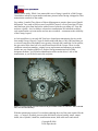
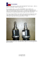
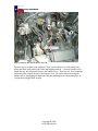
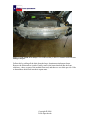
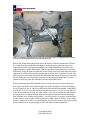
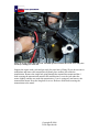
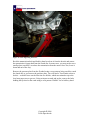
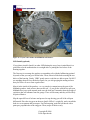
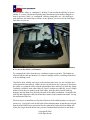
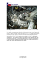
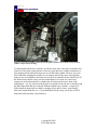
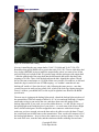
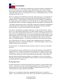
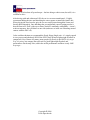
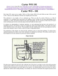
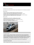
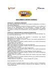
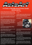
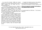
Fixing the Weak Link – Getrag 6-Speed Swap for the MINI Cooper
Some things just have weak links – solid axles with c-clips, any car with Lucas electrics,
and the MINI Cooper’s Midlands transmission. Marginally acceptable for street use, the
Midlands 5-speed gearbox simply cannot stand up to track and autocross punishment like
the Cooper S Getrag 6-speed. With any motorsports use or with any power modifications,
the Midlands gearbox is a ticking time bomb.
My MINI Cooper track car has eaten two of them now, the second of which featured
upgraded synchros, welded reinforcements and extra dowelling. On the first Midlands,
the dogs on the first and second gears rounded off and made for a crunchy engagement
when shifting between the gears. The clincher was that the car would spontaneously pop
out of second gear in fast sweepers – a big problem for a car setup to be neutral, where
throttle steering is impossible mid-corner if there’s no driveline engagement. After a
couple close calls, I sourced a new gearbox.
The second Midlands grenaded in spectacular fashion. It began a slightly odd popping
noise from time to time. One morning on the way to the office, there was a big
*BAAAANG* followed by subsequent smaller, cyclical banging sounds. The car bucked
like crazy in first gear, so I shifted to second. First gear became completely useless. The
pitch of the transmission changed, too. I was used to the old sound. The new sound was,
well, different. It sounded like someone slipped some aggregate of some kind into the
transmission, adding a touch of sand and a couple of BB's for aural sickness. Imagine a
concrete mixer, with a much more metallic tinge. Analysis of the failure revealed that
there were few undamaged teeth on the first gear – the mesh gear was missing two teeth,
too, hence the cyclical banging sound.
Copyright © 2008
Texas Speedwerks
Figure 1 - Generally, this is not what you want to find inside your transmission.
There was simply no way to justify installing another Midlands transmission. The only
logical solution was to borrow the transmission setup from the Cooper S and figure out
how to make it work in the Cooper. After all, the Getrag 6-speed in the Cooper S is
routinely being pushed well over 200 horsepower at the wheels. Professional race teams
are running them with nary a failure.
The Search Begins for Parts
So, off to the web to do as much research as possible, locate a Getrag 6-speed, and see if
it had been done before. I stumbled on a few posts on mini2.com from a tuner in the UK
that had seemingly done a few such swaps. After a couple of exchanges via email, I had
an initial parts list.
A parts list for a MINI project is a good start. The problem, though, is getting the right
part numbers for the parts that you need. Realoem.com is a good source for information,
but the drawings and numbers listed there can be somewhat confusing – the BMW T.I.S.
is not a whole lot better, either.
First things first, though. Before going any further, I had to locate a Getrag 6-speed. I
found one online at a salvage yard in Utah that was brand new, a dealer takeoff for
someone that wanted the factory limited slip differential. Problem was that when it
arrived, it was actually a 2007 Cooper S transmission, made to mate up with the Peugeotsourced 1.8L turbo motor. This brings up a good point – sourcing used parts on the
Copyright © 2008
Texas Speedwerks
internet can be tricky. While I was ensured this was a Getrag 6-speed for a 2006 Cooper,
I should have asked for a part number and some pictures before having it shipped in. That
transmission went back to the sender.
On a whim, I emailed Tony Nuzzo of Nuzzo Motorsports to enquire about a used Quaife
differential. Tony used to field a team of two MINI Cooper S cars in Grand Am ST class,
and I had seen posts from him before with all sorts of parts he was selling off. Tony did
not have a Quaife – but, he did have a brand new transmission! He informed me that it
rode around on the race team trailer and was never touched – a testament to the reliability
of the Getrag 6-speed.
As luck would have it, not only did Tony have a brand new transmission, but it was the
later model Getrag 6-Speed. Cooper S models with build dates of July 2004 and later got
a revised Getrag box with slightly lower gearing. Not only did it make the S a bit quicker,
the gear ratios in the later box are a much better match for the Cooper. There is some
confusion around part numbers, original versus replacement and amongst year models,
but the one you want has a BKE in it. Earlier Getrag transmissions have a BKA
designator on them. You’ll find an identification sticker on the driver’s side of the
transmission, or you’ll find it cast in the end plate.
Figure 2 - Getrag 6-speed. Note the location of the part number sticker for reference. This is a brand
new, never been used beauty!
With the transmission secured, I went about gathering the rest of the parts required for the
swap – a Cooper S flywheel, pressure plate and clutch, release bearing, starter, output
shafts, slave cylinder, clutch line, transmission mount, shift cable tower and various
Copyright © 2008
Texas Speedwerks
assorted hardware. For the flywheel, clutch and pressure plate, I ended up choosing the
Exedy Hyper Single setup. And, since I did not want to pull the transmission ever, ever
again and wondered if I would be sorry if I did not install the Quaife LSD, I went ahead
and ordered one.
One major point of confusion centered around the shift lug and shift cables – I ended up
with two complete sets of MINI’s different styles and really did not need either. One
other point of concern was whether or not the aFe intake would work when we got the car
back together – we were told the battery box would be fine in the OEM location, but that
was also a bit suspect.
Tranny Comparo
Thanks to 101101 on North American Motoring, below are a series of charts showing the
differences between the gear ratios of the Midlands and the early and later 6-speed Getrag
– it’s fairly obvious that the late model Getrag 6 is the one to find.
Figure 3 - Midlands gear ratios
Copyright © 2008
Texas Speedwerks
Figure 4 - Early Getrag 6-Speed ratios
Figure 5 - Late Getrag 6-speed ratios, where 1st and 2nd are closer to the original Midlands ratios.
As mentioned later on, 3rd and 4th gear are quite pleasing!
Copyright © 2008
Texas Speedwerks
Rounding ‘Em Up
With a list of parts in hand, it was off to track down the right numbers and get the parts
on order. A solid MINI parts department helps out a whole lot when trying to track down
the right bits and pieces – don’t expect them to know how to help you out with
everything since this is a very unique project, but they will be able to help get you the
right stuff.
Before ordering parts, I checked the transmission over well to see what I needed. I
suggest that you do the same, since you may already have some of the parts listed below
or you may need more parts. Specifically, look for the backup light switch and the
Bowden cable bracket (23-11-7-509-737). You should also inspect all seals and the shift
selector levers. If the transmission is used, you should look for any leaks, missing ears,
cracks, etc. as well.
Transmission Swap OEM Parts List
Part Number
Description
31-60-7-514-480
Output Shaft – Right (Passenger side)
31-60-7-514-479
Output Shaft – Left (Driver side)
31-60-7-518-257
Dustcover (qty. 2)
31-60-7-518-262
Dustcover
31-60-7-518-264
Lock Ring
31-10-6-773-005
Hex Nut (for output shafts)
12-41-1-517-328
Starter
21-51-7-547-077
Clutch Release Bearing
21-51-6-777-428
Output Cylinder Clutch (slave cylinder)
21-52-6-759-854
Pipe (connects clutch line to slave)
21-52-6-759-855
Pipe Bracket
22-31-6-754-422
Support Bracket, Transmission
22-11-6-756-599
M12 x 45 bolts for support bracket
23-11-7-509-737
Bracket, Bowden cable
23-11-7-527-716
Backup Light Switch
I ordered the dustcovers and lock ring when I was rounding up my parts, and I am
certainly glad that I had them. The output shafts are remanufactured parts and you are
supposed to get them complete, with all the dustcovers and lock ring in place – my set
was missing one of the dustcovers, so I slapped it on the output shaft. I just kept the
others as spare parts.
In addition to the parts listed above, you will need to choose a flywheel, pressure plate
and clutch of your choice. If you choose to install a Quaife LSD during the process, you
will need to source two new differential bearings, part number LM501349 (Napa is a
good source). Because you have to split the transmission case to install the Quaife, you
will also need anaerobic sealant when rejoining the halves. If you simply cannot find
Copyright © 2008
Texas Speedwerks
anaerobic sealant, look for a product called ‘The Right Stuff’ from Permatex – while it is
not the ‘recommended’ sealant, it works just fine.
For re-assembly of the car, you will need MINI/BMW coolant, distilled water,
transmission fluid and brake fluid of your choice. If you plan on swapping your shift
cables, you’ll need to drop the exhaust system to access the bottom of the shift lug so you
should replace the exhaust donut gasket and the copper nuts on the exhaust bolts.
The Cooper S output shafts have more splines on the transmission side than the Cooper
output shafts, which is why they have to be replaced during the swap. The bonus of
replacing the output shafts is that you get brand new CV joints!
Figure 6 - Tranny side of the driver’s side output shafts - Cooper on the left, Cooper S on the right.
Note the relief oiling in the Cooper S output shaft and more splines. Also note the missing dustcover glad I ordered those!
Copyright © 2008
Texas Speedwerks
Figure 7 - Comparison of output shafts. The new shafts are obviously the clean ones - note that the
passenger output shaft from the Cooper S has a longer prop shaft.
As far as the shift lug and cables are concerned, I think it’s better to match the shift lug
and cables to your car’s build date than it is to match it up to the build date of the
transmission. If your shifter is a bit tired or sloppy, this is a good time to replace the
cables – but, you can retain your original shift lug. Likewise, it is good to have them on
hand in case you damage the cable ends during disassembly.
The key is matching the cables to the shift lug, which as I suggested is matched to your
car’s build date. As far as we could tell, the cables look identical in length between year
models and the ends are the same – some of the hardware has changed among the
different part numbers, but it appears that they are all interchangeable. Still, I think that
the safest course of action is to source new cables and clips (shift lug side and shift cable
tower side) that match your shift lug. Don’t forget a 6-speed shift knob, unless you revel
in confusing anyone else that might have to drive your car.
BMW loves special tools – you can usually find a workaround if you have a large
assortment of tools, but there are some that really do make life easier for this job and a
couple of really cheap ones that will save you from a whole lot of pain. Special tool 23 4
010 makes getting the shift cables off the ball joints a cinch. The transmission output
flange seal protectors, special tool 24 8 120, will keep you from nicking the seals when
you install the output shafts – nothing is worse than filling up your new transmission and
watching it leave the transmission via a nicked seal (trust me on this one). Clutch
alignment tool 21 2 210 makes centering up the clutch easy – you may be able to borrow
Copyright © 2008
Texas Speedwerks
this tool from your local dealer. Special tool 21 5 030 makes bleeding the new slave
cylinder a snap, or you can make one quite easily with some bar stock, long bolts,
washers and wing nuts.
Other than that, I would recommend that you have access to the following tools:
• Full metric wrench set
• ½”, 3/8”, ¼” ratchets and metric sockets
• Air tools
• Screwdrivers
• Torque wrenches
• Pickle fork
• Rubber hammer
• Jack and jack stands
• Dikes and assorted pliers
• Wire strippers
• Soldering iron
• Bentley Service Manual
It is very handy to have the Bentley Service Manual on hand in case you get stuck at
some point, and this article is not a substitute for the detail in the manual – every DIY’er
should have this on hand, if for nothing other than to have a source for looking up torque
specifications. Double-check all torque specs referenced here, as they may have changed
between model years.
Let the Fun Begin
Obviously, the first step is pulling the transmission from the car – on the MINI, this is no
small feat, since you pretty much have to disassemble the entire front end to get at your
target. Make sure you have a bunch of Ziploc bags handy and a permanent marker –
bagging each assembly’s hardware as you tear down makes it a WHOLE lot easier to put
it back together right. Nobody likes seeing extra hardware laying around when they’re
done and then trying to remember where it goes.
First things first – get the car up on 4 jackstands and make sure that it is extremely stable.
You’ll be spending a lot of time in, around, and under the car, so making sure that it’s
completely stable and secure is extremely important. I like to try and get it as high as
possible. Once airborne, remove the front wheels.
I started on the top end, pulling aFe intake and hardware first, followed by the battery,
battery box and ECU. This exposed the top end of the transmission and opens things up a
bit for future steps. Then, I dropped the rear section of the exhaust, removing the bolts
from the flange near the catalytic converter, followed by the rear exhaust hangers, and
then the center plate that houses the center hangers. This is best done with two people!
Copyright © 2008
Texas Speedwerks
Figure 8 - Battery Box and aFe intake removed.
The next step is to remove the undertray. Then, remove the driver’s side fender liner,
taking out those little plastic body bolts and bagging them up – you may find that a few
break and may need replaced. Remove the bumper cover – there are two Torx head bolts
and some plastic clips at the top of the bumper cover. Be careful when removing the
bumper cover, unplugging all connectors and then marking them with masking tape so
you get them plugged back in right.
Copyright © 2008
Texas Speedwerks
Figure 9 - Oooh, nekkid! Front bumper cover removed. And yes, the A/C condenser took some cone
damage in the past.
Follow this by pulling all the bolts from the large, aluminum main bumper beam.
Remove the beam and set it aside. Finally, remove the horns that bolt into the front
subframe – these are part of the modular front end, and there are two bolts per side. I like
to thread those bolts back into their capture nuts.
Copyright © 2008
Texas Speedwerks
Figure 10 - Aluminum beam removed.
Place a large pan under the driver’s side where the lower radiator hose comes in – loosen
the clamp, slide it back, and pull the hose. I’ll almost guarantee that it’s going to go
everywhere, so be prepared to mop up a bit. Once it has stopped flowing quite as fast,
remove the cooling system fill cap. If you squeeze the upper radiator hose after the elbow
(near the inlet side, to the left of the intake manifold), you can extract quite a bit more by
pumping it out. If you have pets, be extremely careful with the coolant once it’s finished
draining and make sure there’s no extra fluid on the ground.
Once good and drained, slide the lower radiator hose up and out of the way. Unplug the
fan wiring from the harness located on the upper right corner of the radiator, and remove
the 10mm bolt that holds the bracket and A/C service port in place. Unplug the connector
from the horns and label the connectors. Remove the two bolts that hold the A/C
condenser to the radiator core support, and be ready to thread it out of the way. Slowly
slide the radiator and radiator core support structure off the front of the car, being careful
to avoid hitting the A/C condenser. It’s definitely easier with two people. Once the
radiator core support is clear, you can hang the A/C condenser back on the front of the
car using one of the protruding studs used to secure the core support. Immediately take
the radiator core support outside and drain the rest of the coolant by slowly rocking it
back and forth. If you wish, you can flush it with water to ensure all the coolant is gone.
Copyright © 2008
Texas Speedwerks
Figure 11 - Radiator core support and radiator removed.
Now, it’s time to drop the front subframe. Begin by disconnecting the lower end of the
front swaybar links on each side, making sure that they are well out of the way. Unclip
the ABS sensors from the front subframe horns and move aside. Remove the two 13mm
bolts that hold the lower a-arm balljoint housing into the hub carrier on each side, and
persuade them to break free from the hub carrier using a rubber hammer. Remove the nut
from the steering tie-rod balljoint and use a pickle fork gently to remove them from the
hub carrier – sometimes they just fall out, but sometimes they need a bit of persuasion! In
the engine compartment, remove the pinch bolt holding the power steering reservoir to
the bulkhead, as well as the bolts for the bracket. Slide the reservoir out of the bracket
and remove the bracket from the engine compartment. Under the car, reach up and
disconnect the power steering pump electric connections (there are two) and the power
steering fan connection. Remove the bolt that connects the steering shaft to the rack and
pinion, slide the connection back, and bag the bolt. NOW, support the center of the lower
subframe with a jack and secure the subframe to the jack – a transmission jack works
particularly well. Remove the bolts from the lower engine vibration damper. Remove the
control arm bushing bracket bolts (aka the ‘lollipops’). Remove the 6 bolts at the rear of
the subframe. Finally, remove the two front bolts that bolt into the unibody at the front of
the subframe. Have someone guide the power steering reservoir down between the
bulkhead and the engine as you lower the jack. Roll the front subframe from under the
car and move it out of the way – to avoid spilling power steering fluid, use a stick and
some duct tape to hold the reservoir upright.
Copyright © 2008
Texas Speedwerks
Figure 12 - Subframe removed and out of the way. Note this is before we rigged the power steering
reservoir to remain upright using a stick and some duct tape.
Remove the exhaust heat shield from above the header. Drain the transmission. Remove
the 3 bolts from the jackshaft bearing support on the passenger side, and remove the
output shaft retainer clip from the passenger side of the transmission (look where the
output shaft goes into the differential). Slide the passenger output shaft (axle) out of the
differential. Using an impact wrench and 32mm socket, remove the axle flange nut on the
outboard side of the hub and tap the splined end out of the hub. On the driver’s side, pull
firmly to remove the output shaft from the differential and repeat the process of removing
the axle flange nut. You may need to pry between the gearbox housing and CV joint to
release the lock ring from the differential. Set the output shafts aside.
Remove the starter heat shield from the starter, remove the electrical connections and
then remove the starter itself from the upper side of the transmission. Keep all hardware
as you’ll need to re-use it. Unclip the shift cables from the shift mechanism, using BMW
special tool 23 4 010 – the other method, sans the special tool, is to use two screwdrivers
to pry them off (this is not easy, nor ideal, and it’s very easy to damage the ends without
the special tool). Unclip the backup light switch connector. Remove the two mounting
bolts from the slave cylinder and bag them – you will need to re-use these 8x30mm bolts
for the Getrag’s slave cylinder. Remove the slave cylinder from its bracket. If your brake
booster vacuum line is tied to your transmission, you’ll need to remove any clips securing
it to the transmission, and to possibly pull the line from the intake manifold.
Copyright © 2008
Texas Speedwerks
Figure 13 - Prying off the shift cable ends - the BMW special tool makes this a LOT easier and you're
less likely to damage the cable ends.
Support the engine with a jack and get ready for some heavy lifting! If you do not want to
manipulate and remove the transmission by hand, place another jack under the
transmission. Remove the single bolt going through the transmission mount and the 4
bolts securing the transmission mount to the transmission. Lower the jack under the
motor slightly (and the one under the transmission, if you’re using one) and remove the
transmission mount. Keep the long bolt for re-use. Remove all the bolts securing the
transmission to the motor.
Copyright © 2008
Texas Speedwerks
Figure 14 - Jack supporting the motor.
Rock the transmission back and forth by hand to release it from the dowels and extract
the transmission’s input shaft from the clutch disc. In some cases, you may need to use a
small prybar (carefully!) to release the transmission from the motor. Once free, lower it
down and out of the way.
Remove the pressure plate from the flywheel using a cross pattern, being careful to catch
the clutch disc as you remove the pressure plate. You will need a Torx female socket to
do this – we didn’t have one the first time we did this, which necessitated a trip to the
local auto parts store to get one. Using an impact wrench and socket, remove the bolts
holding the flywheel to the crank using a cross pattern. Wallah! You’re halfway there!
Copyright © 2008
Texas Speedwerks
Figure 15 - Anyone order another dead Midlands transmission?
LSD Install (optional)
If you plan to install a Quaife (or other LSD) during the swap, keep in mind that it is a
good idea to let the transmission sit overnight after re-joining the two halves of the
housing together.
The first step is to arrange the gearbox on something soft, with the bellhousing pointed
skyward so that you can get to all the bolts. Then, remove all the bolts securing the two
halves of the housing. Gently, VERY gently start to work the two halves apart. Do NOT
use anything sharp to force the halves apart, else you risk gouging the mating surfaces
that you’ll have to use to form a gasket later.
Marvel at the inside of the gearbox – so very simple in comparison to the guts of the
Midlands gearbox. And, trust me here on this one – if you get the wild idea to split your
Midlands box just to poke around, make sure the kids aren’t around to hear the strings of
expletives that will emanate from the garage. There will be many and they will be likely
be quite offensive.
Slip the open diff out of its home and proceed to zap the ring gear off of the old open
differential. Place the ring gear on the new Quaife LSD (it’s a tight fit), and re-install the
bolts in a cross pattern and pre-torque. For final torquing, mark the bolt heads with a
paint pen, perpendicular to the ring gear. Then, torque all bolts evenly.
Copyright © 2008
Texas Speedwerks
Figure 16 - Painted bolt heads, showing final location after torquing.
Preheat your oven to 350 degrees. No, we’re not baking here, but we are going to use
heat to help us get the new differential bearings on our Quaife LSD. While the oven is
heating, take your shiny new differential bearings outside, place them in a pan, and
proceed to blast the oil off them with Berryman’s B12 Carb Cleaner. Air dry the nowclean bearings with the blow gun attachment on your air compressor. You do NOT want
to bake your bearings with the shipping oil on them, else you’ll end up with nasty, coked
up bearings that you will not be able to use.
When the oven is at 350 and your bearings are nice and clean, place them on a clean
cookie sheet and put them in the oven. Set the timer for 20 minutes. Bring the Quaife in
and set it on a firm, level surface, grab some leather gloves and get ready for a quick
transfer. After the timer goes off, remove ONE bearing from the oven and drop it on to
the Quaife, immediately making sure that it seats and allow it to cool for a few minutes.
Flip the Quaife over and repeat the process on the other side.
While the bearings are cooling, prep the mating surfaces of the two transmission housing
halves. You can carefully remove the anaerobic sealant using a single-edge razor blade,
but be EXTREMELY careful not to nick the mating surfaces. Final cleanup can be done
with a bit of B12 sprayed onto a rag. Make sure the surface is clean and dry.
Once the new differential assembly is cooled completely, flood the new bearings with
tranny oil and drop the Quaife into its new home in your gearbox. Follow the directions
on the sealant you’ve chosen to rejoin the transmission housing halves – BMW specifies
anaerobic sealant, but we have successfully used The Right Stuff from Permatex. Note
that most have a very short working time, so once you start the process you need to
quickly complete it. Re-install all the housing bolts and tighten them up.
Installing the Getrag Goodness
My first step was to pull the shift lug and cables to see how they compared with the ‘S’
versions that I had sitting there for parts, which meant pulling all of the heat shields to
access the bottom of the shift lug and expose the shift cables. Inside the car, pull the trim
ring off the shift console, pull the shift knob off, and cut the wire tie securing the boot to
the shifter and remove the boot. Under the car, remove the 4 Torx bolts holding the shift
lug into the tunnel and then extract the shift lug from the car – there are clips on the top,
so make sure to free them first.
Copyright © 2008
Texas Speedwerks
My car had the ‘white’ or ‘condition A’ shift lug. Turns out that the shift lug in my car
and the ‘S’ version I had ordered had the same manufacturer part number stamped on
them. I also had a ‘black’ or ‘condition B’ shift lug sitting there, too – this shift lug is
quite different, but should also work fine. In my opinion, you can re-use the shift lug in
and cables in your car.
Figure 17 - Comparing the shift lugs. The white one is 'condition A' and the black one is 'condition
B'. Use the one that matches your build date.
We compared the cables from the two ‘conditions’ against each other. The lengths are
identical and the ends are identical. So, what we thought could be a challenge turned out
to be no challenge at all.
I decided to stick with the same style as the one that came in my car, but I used the newin-box part that I had ordered. I didn’t need to, but decided to use it anyway. I did replace
the cables, too, using the cables with the part numbers that ‘matched’ my shift lug. Again,
I probably could have used either cable set. Since I used the new shift lug, it was a simple
matter to slide the new gaskets on the shift cables, slide the cables into the shift lug
housing, and clip them on to the ball joint ends of the shifter mechanism. I reinstalled the
shift lug and clipped the cables back into their retainer in the transmission tunnel, leaving
the transmission side free.
The next step is to install the new flywheel. Because of the odd bolt pattern, it only goes
on one way. I used red Loctite on the bolts before threading them in and then pre-torqued
them by hand. BMW has a special tool for the crank pulley end to hold everything still
while you torque the bolts down, but I put one of transmission bolts back in and used a
Copyright © 2008
Texas Speedwerks
big screwdriver and the teeth on the flywheel. The torque spec is 59 ft/lbs for the Cooper
crank, and you need to use a cross pattern. The Bentley Service Manual has a great
illustration of the pattern.
Install the clutch and pressure plate back onto the flywheel, using BMW special tool 21 2
210 to center the clutch disc. The plastic tools that come with the clutch and pressure
plate kits are useless, since the MINI crank has no pilot bushing between the engine and
the gearbox. This is one spot where the special tool will save a lot of frustration. There is
a cross pattern for tightening the pressure plate to the flywheel as well – the torque spec
for the OEM bits is 21 ft/lbs, but the spec for the Exedy unit was 23 ft/lbs.
Figure 18 - Exedy Hyper Single flywheel, clutch and pressure plate installed. What a work of art too bad nobody will ever see it! Note that the clutch disc is fairly well centered and ready to accept
the input shaft from the new Getrag.
Copyright © 2008
Texas Speedwerks
Now, it’s time to wrestle the new transmission into place. Before you start, slide the new
release bearing onto the input shaft of the transmission. Be patient and ensure you have
enough help and support – you can always place a jack under the tranny if you need to do
so. It is critical to ensure that you match the angle of the transmission and engine for
mating – just go slow, wiggle it back and forth, and slide it home. And, yes, be prepared
for a whole lot of raunchy innuendo from your shop buddies.
Figure 19 - Wrestling the new transmission into place. Oh baby!
Once fully seated, install all the bolts and pre-torque until snug. After all bolts are pretorqued, final torque the transmission to the engine – the spec is 63 ft/lbs.
Copyright © 2008
Texas Speedwerks
Figure 20 - Transmission bolted up, bolts torqued, ready to move on!
Slide the new transmission mount into place and use the new M12 bolts to secure it to the
transmission. Torque to 49 ft/lbs. Then, jack the motor up and guide the mount into the
arm. Replace the bolt to hang the transmission mount in the support bracket and torque to
50 ft/lbs.
Copyright © 2008
Texas Speedwerks
Figure 21 - New transmission mount in place. Note the original slave cylinder is still connected up
and awaiting modification.
Now that the new transmission is bolted in and the mount is in place, you no longer need
the jack to support the engine. Bolt the new starter (12-41-1-517-328) into place, torquing
the bolts to 63 ft/lbs., connect the electrical connections, and re-install the heat shield.
Grab the Pipe (21-52-6-759-854) and new slave cylinder (21-51-6-777-428) from the
OEM parts pile. Note that there is actually a part clipped onto the end of the clutch line –
do not unclip the line there, as you will need that to mate up to the pipe (the silver piece
in Figure 18 and 20). Unclip the line from the original slave cylinder and quickly clip it
into the pipe. Clip the pipe into the new slave cylinder.
Copyright © 2008
Texas Speedwerks
Figure 22 - New slave cylinder connected. Note the ghetto fabulous tool we made to keep the slave
cylinder compressed for bleeding.
Go ahead and bleed the slave cylinder. It will take some time, since there’s bound to be a
whole lot of air in the system because of the new pipe and slave cylinder. Remember to
keep topping off the brake fluid reservoir as you bleed the cylinder. The best way to do
this is manually, pushing the clutch lever in, opening the bleeder valve, and repeating
until you see no air bubbles. Note that you may have to manually lift the clutch lever off
the floor between bleeds. Once you have ensured there is no more air, remove the
compressor tool and put the slave cylinder into its bracket on the lower front of the
transmission – it’s very obvious why the pipe is required! Secure the slave cylinder using
the M8x30mm bolts that you removed from the original slave cylinder – torque to 18
ft/lbs. Install the pipe bracket to hold everything secure and for a nice, clean install!
Check the clutch inside the car – if you installed the Exedy setup, you’ll note a VERY
firm pedal with extremely crisp breakover.
Copyright © 2008
Texas Speedwerks
Figure 23 - Pipe bracket in place, securing the clutch line and pipe.
Install the shift cable bracket (23-11-7-509-737, Bracket, Bowden cable), reusing the
three bolts taken off the old shift cable bracket. Torque to 16 ft/lbs. Clip the cables into
the bracket using new clips or by recycling the clips off the old shift cable bracket. Do
NOT clip the cable ends onto the ball joints yet – you will want to check the shift cables
for clearance around the heater core hoses. We noted that they were awfully close to them
and were afraid that they would bind or make shifting harder. Our solution was to move
the hose clamps on the heater core hoses so that we could rotate them – rotating them up
created enough clearance that we were happy with the result. With this solved, clip the
cable ends onto the ball joints. Climb into the car and work through all 6 gears and
reverse – you may actually find that you need to depress the clutch. At this point, you can
go ahead and re-installed the heat shielding in the tunnel. Likewise, you can re-install the
shift boot, trim ring, and install the new 6-speed shift knob.
Copyright © 2008
Texas Speedwerks
Figure 24 - Final shift cable routing.
Next up is installing the new output shafts (31-60-7-514-480 and 31-60-7-514-479).
Remember that special BMW tool to protect the seals (24 8 120)? Time to slide those bad
boys in place BEFORE trying to install the output shafts, unless you want to lose all the
precious fluid you’re about to add. We opted to start with the passenger-side output shaft
– slide the splined end of the prop shaft into the differential and replace the three bolts,
torquing to 18 ft/lbs. Then, work the hub end into the hub, aligning the splines. Thread
the new hex nut on and torque to 134 ft/lbs. Make sure you take a screwdriver or drift and
knock the edge in on the hex nut AFTER torquing – we wouldn’t want that axle nut
backing off would we? On to the driver’s side, following the same process – note that
you need to press in until you hear a little click, which is the lock ring clipping into place.
Once it’s in there, you should NOT be able to pull it right back out. Remove the BMW
special tools.
The next step is rigging up the backup light switch – thread the backup light switch out of
the transmission. Grab two strands of about 14-16” of wire and strip both ends. Crimp the
small stake-on lugs to one end of the wire, and shove them on to the spades IN the
backup light switch. If you wish, you can also solder them on – we did. Fill the cavity of
the backup light switch with the goo of your choice – we used some of the leftover Right
Stuff, which worked great. We then wrapped the new connector with electrical tape –
make sure you leave enough wire on the bare ends to be able to work with them. Thread
the switch back into its little home on the transmission. Then, cut the old connector off of
the backup light harness – keep it close to the connector so you have plenty of wire. Strip
the ends of the wire, twist the ends, and then tin them with the soldering iron and some
Copyright © 2008
Texas Speedwerks
solder. Do the same for the ends of your new, modified backup light switch. Slide a bit of
shrink tubing over each wire, and commence to joining the wires – soldering works best,
but a crimp connector would also work. The orientation does not matter – we tested the
switches. Once soldered, slide the shrink tubing up and shrink it down. We then wrapped
the splice with electrical tape. Secure the new harness with a couple of wire ties.
Figure 25 - Wrapping up the new backup light switch.
Now that the transmission is in place and the output shafts and switch are in, add fluid to
the transmission – your choice. We’ve been running Royal Purple Syncromax, but the
OEM fluid and Redline’s products are also fine choices. You’ll need a couple of quarts.
Slide the jack back under your front subframe and wheel it back into place – slowly start
jacking it back up. Remember to guide the power steering reservoir back up through the
miniscule space between the header and bulkhead. As soon as the connectors reach,
reconnect all the wiring harnesses that you disconnected – power steering pump
connections, power steering fan connections. Even though we’ve done this a few times
now, we made the mistake of fully installing the subframe first – getting the connectors
back into place is an exercise in patience once it is fully installed. I blame the beer.
Once the subframe is located, it’s time to install all the bolts. The torque spec from the
front bolts on the ‘horns’ of the subframe is 74 ft/lbs. The torque spec for the rear bolts is
74 ft/lbs. Re-install the two 13mm bolts that hold the lower a-arm balljoint housings into
the hub carrier on each side and torque to 41 ft/lbs. Slip the steering tie-rod balljoints
back into their homes, install the nuts, and torque to 41 ft/lbs. Re-connect the steering
Copyright © 2008
Texas Speedwerks
shaft using the wonky bolt – it’s a good time to ensure that the steering wheel has not
moved from where it was when the process began. If you get stuck, you can count the
revolutions from stop-to-stop and then put it right back in the center BEFORE connecting
the steering joint. Re-connect the front swaybar endlinks. Attach the power steering
reservoir bracket to the bulkhead and clamp the reservoir back into place using the pinch
bolt. Slide the modular front end connectors back onto the subframe and install the bolts,
torquing to 74 ft/lbs. Remember to re-attach the ABS sensors, too.
Grab the radiator and core support and slide it over into place. It’s a bit of a chore to
thread it back through all of the lines for the A/C condenser, so it is best achieved with a
helper. The service port line is the biggest beating, it seems, so be careful to get it back
into the right spot. Slide the core support back onto the studs and re-connect all electrical
connections. Re-connect the lower radiator hose.
Follow this by re-installing all the bolts and nuts from the large, aluminum main bumper
beam. Slide the bumper cover near its final location and plug all connectors back into
their respective locations. Secure it back in place with the bumper cover hardware. Finish
up by installing the undertray and the driver’s side fender liner.
The final step before the test drive is refilling and burping the coolant system. On the
Cooper, this is not the easiest thing in the world and requires a ton of patience. Make sure
you mix your coolant with distilled water, since it is not pre-diluted. A clean 2.5 gallon
bucket makes it easier. We started by covering the alternator with a cloth and removing
the bleed screw on the top radiator hose elbow – then, start filling through the coolant
filler neck. Pour VERY slowly. Once it starts weeping from the bleed screw or backs up
into the coolant filler neck, stop. Thread the bleed screw back in, but leave it slightly
open, and remove the cloth protecting the alternator from overflow. Pour some coolant
mix into the overflow tank. Now, it’s time to start the car – make sure the car is in neutral
first! Turn the heat to HI and start watching the coolant filler level. As the system
circulates, the bleed screw and coolant filler neck will bubble – as needed, add coolant
mix. When the thermostat opens, the level may drop, so be prepared to add as necessary.
Also, keep a close eye on the temperature gauge in the car. Once you’re convinced the
system is thoroughly burped and full, close the bleeder screw and install the cap on the
coolant filler neck. Shut the car off.
Re-install the front wheels and get the car off the jack stands – torque the wheels to spec.
Roll the car out into the driveway and it’s time to test the clutch throw. Why? Prior
experience with the SPEC setup on the Cooper and with the Midlands transmission told
us to do it…
On the Exedy setup, you could feel that the clutch fully disengage when pushed all the
way to the floor and began to re-engage when about 1-1.5” off the firewall. Remember
that crisp breakover I mentioned? Pure sweetness! However, on the previous SPEC setup
we were running, you could not completely discern the engagement/disengagement
points. The way to test the setup is to put the car in neutral, push the clutch all the way in,
and start the car. With the clutch pedal fully in, attempt to put the car into first gear and
Copyright © 2008
Texas Speedwerks
see what happens – the transmission should easily go into gear and the car should not roll
at all. IF the car rolls, you’re going to need to adjust the throw of the clutch. With the
Exedy setup, the breakover was perfect and there was no adjustment necessary. With the
clutch fully depressed, the car sat still and it was easy to work through the gears. And, the
engagement was spot on, too.
When we installed the last Midlands transmission, things did not go so well with this test
– the car would NOT go into gear (any gear) with the clutch fully depressed. With the
pedal held about 1” off the firewall, it would go into gear fine and the car remained still –
if you then pressed the clutch all the way to the firewall, the car would roll forward! This
meant that the clutch was actually re-engaging when the clutch pedal was fully depressed
– the fingers on the pressure plate were probably curling back around and re-engaging the
clutch. Not good! We ended up using a homebrew clutch stop to keep the pedal from
traveling all the way to the firewall, which solved the problem.
Once you are satisfied that everything’s ready to go, it’s time for the best part – the test
drive. For us, this moment came about 12:30 AM on Sunday morning. It’s a good idea to
take it easy on the clutch for the first 300 miles or so, but you can wind the car out to see
what you have accomplished. Keep a close eye on the temperature gauge, though – if you
didn’t burp the system well enough, it won’t take long before the car gets into the danger
zone. If that happens, pull over and shut down immediately and let the car cool down.
Then, try and inch back home – you may have to shut the car down more than once and
let it cool back down. Of course, we wouldn’t know anything about this, except that it
happened the first time we replaced the Midlands… Hah! If this happens, let the car cool
and bleed and burp the system again.
On the test drive, row through all the gears and keep a sharp ear out for any odd sounds.
Have fun!
If you note that your cruise control does not work after the install, try resetting the ECU
using a Peake tool – follow the instructions on resetting the CEL light to clear all codes
and then give it a shot. This worked for us, and now the cruise works again! Other things
to check if the cruise doesn’t work are the brake and clutch switches – ensure they are
properly adjusted and functioning, and then try resetting the codes (if you have them).
The codes for the clutch switch malfunction and cruise/brake switch circuit malfunctions
are P0704 and P0571, respectively.
Driving Impressions
My initial impressions are that the late model Getrag-6 gearbox is a superb match for the
Cooper – especially our Cooper, which is making gobs more power than a stocker. First
and second gears are a hoot, but third and fourth are simply the most fun. In 6th gear,
cruising at about 70 mph is right around 3K RPM’s.
With my car’s powerband, acceleration is smooth and brisk all the way from idle to
redline… My car really shines from 3.5K-6.9K, where the Shrick cam and our head work
Copyright © 2008
Texas Speedwerks
really pay off in buckets of hp and torque – buckets being a relative term, but still, it is a
real hoot to drive.
After driving with and without an LSD, the car is even more transformed – I highly
recommend taking the time and absorbing the extra expense to install the Quaife unit.
Where the inside wheel used to spin, the car now tracks better through the corner and
literally RIPS through it. One odd thing that you might find yourself getting used to is
how the front will ‘walk’ sideways at times, but this is eminently controllable – it won’t
wash out anymore, but will skitter to one side (and more so in the wet if hustling around
corners with the DSC off).
I also would not hesitate to recommend the Exedy Hyper Single unit – it’s simply superb
in every aspect and absolutely KILLS the SPEC Stage III and a lightweight flywheel in
comparison. Now I know why many, many people say Exedy is the ONLY way to go.
Yes, it’s pricey, but compare the total cost to a good lightweight flywheel and
performance clutch setup! Now, add in the stellar performance and there is only ONE
way to go…
Copyright © 2008
Texas Speedwerks