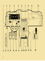
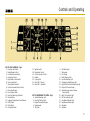
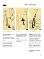
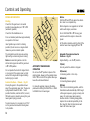
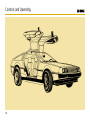
1
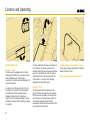
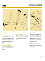
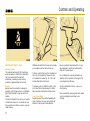
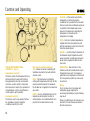
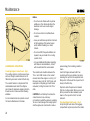
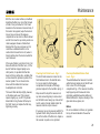
De Lorean Part Number 113090, the Owner’s
Handbook, can be viewed using any Adobe Acrobat 2.0
reader (available from the Adobe web site http://www.adobe.com).
In the interest of historical accuracy, I decided to
leave the errors (typographical and otherwise) in this recreation of the Owners Handbook. All are relatively
minor, primarily misspellings. Owners of De Lorean
automobiles will want to consult with either the De
Lorean Owners Association or a qualified service center
for current maintenance information.
While it is possible to purchase an actual De Lorean
Owners Handbook from a variety of different sources,
most are priced at about $35 as this is written.While a
digital version like this is no substitute from a collectors
standpoint, many of the De Loreans changing hands
today no longer have an Owners Handbook.This digital
version, as an exact recreation, does offer much useful
information to the new De Lorean owner. Additionally,
even if you do have an Owners Handbook, you now have
the option of “putting it away” and using this digital
version.
To register this Handbook, send your name, address,
and email address to [email protected]
I will email you the address to mail your payment of $15.
When your payment is received I will email you
the unlocked version of the file.
All proceeds benefit the DMCNews - The DeLorean
Mailing List.
For more digital DeLorean data, contact : [email protected]
http://www.dmcnews.com
De Lorean
Owner’s
Handbook
Part No. 113090
Published by
De Lorean Motor Cars (1982) Limited
Introduction
We would like to take the opportunity to
thank you for selecting a De Lorean motor
car and to wish you many years of happy
and trouble free motoring.
This handbook should be considered s
permanent part of the vehicle. Please read
it carefully as it contains important
operating, maintenance and safety
information.
The first part of the book tells you how to
operate the controls, switches and
accessories and gives the necessary
information on driving and operating your
car.
Part Two gives a full summary of the
maintenance required by your car. We
strongly recommend that this is entrusted
to your dealer who has the necessary
expertise and specialised equipment.
Part Three gives details on emissions
applicable to the North American Market
and part Four contains useful information
on emergency operating procedures.
Finally Part five is the General Information
section covering vehicle specification,
capacities, etc.
2
Part 1 - Controls and Operating
Part 2 - Maintenance
Part 3 - Emissions Control
System (North America)
Part 4 - Emergency Operating
Procedures
Part 5 - General Information
Note:
The specifications and descriptions
contained in this manual were accurate at
the time they were approved for printing.
De Lorean Motor Cars (1982) Ltd., reserves
the right to make changes at any time
without notice.
Controls and Operating
Key to Instrument Cluster
5
Seat Back Recline Adjustment
Seat Back Release Lever
Parking Brake
Doors and Locks
External
Internal
Locking Storage Compartment
6
6
6
6
Inertia Seat Belts
Warning System
Wearing
Care of Seat belts
8
8
8
8
Seats
Seat Travel Adjustment
7
7
Steering Column Controls
9
Luggage Compartment
13
Centre Console Controls
9
Fuel Filler Cap
13
Engine Compartment
13
Driving Information
Starting
Selector Positions – Manual
14
14
14
Automatic Transmission Operation
Automatic transmission Selector
Positions
Warming Up
Running In
Economical Operation
14
Key to Car Controls
4-5
Centre Instrument Panel Controls
Temperature Control
Fan Speed Control
Main Selector Switch Positions
Light Switch
Hazard Warning Flasher
Illumination Control
Rear Window Defogger Indicator
Cooling Fan Fail Indicator
Door Locks Warning Indicator
7
7
7
10
10
10
10
11
11
11
11
11
11
Ignition Switch and Anti-Theft
Deterrent Steering Column Lock
11
Interior Lights
12
Remote Control Side View Mirrors
Interior Rear View Mirror
12
12
Steering Column Adjustment
12
14
15
15
15
4
Controls and Operating
KEY TO CAR CONTROLS – Fig. 1
1. Courtesy Light Switch
2. Side WIndow Air Duct
3. Left Hand Column Switch
4. Instrument Cluster
5. Right Hand Column Switch
6. Face-level Air Vent
7. Stereo Radio/Cassette
8. Centre Instrument Panel Controls
9. Glove Box Release
10. Front Speaker Grille
11. Door Ajar Warning Light Switch
12. Parking Brake
13. Luggage Compartment Cover Release
14. Clutch Pedal
15. Brake Pedal
16. Accelerator Pedal
17.
18.
19.
20.
21.
22.
23.
Ignition Switch
Illumination Control
Centre Console Controls
Ashtray
Cigar Lighter
Gear Shift – Manual
Gear Shift – Automatic
KEY TO INSTRUMENT CLUSTER – Fig. 2
1. Seat belt Warning Light
2. Door Ajar Warning Light
3. Engine Temperature Gauge
4. Speedometer
5. Trip Meter
6.
7.
8.
9.
10.
11.
12.
13.
14.
15.
16.
17.
18.
19.
20.
Trip Meter Reset
Tachometer
Fuel Gauge
Brake Warning Light
Low Fuel Warning Light
Charging System Warning Light
Engine Oil Low Pressure Warning Light
Engine Oil Pressure Gauge
Lambda (oxygen sensor) Service
Warning Light
Right Turn Indicator Light
Left Turn Indicator Light
Low Beam Indicator Light
High Beam Indicator Light
Odometer
Voltmeter
5
Controls and Operating
DOORS AND LOCKS
External – Fig. 3
The De Lorean is equipped with a central
locking system which locks or unlocks both
doors simultaneously. The locking or
unlocking of one door will automatically lock
or unlock the other.
To unlock, insert the key and turn it to the
rear of the car, return it to vertical position
and withdraw. Lift the external release
handle and raise door to its maximum
height. Due to the gull-wing design, caution
should be exercised when entering or exiting
the vehicle.
6
To close, pull the door down and continue to
close the door by placing a hand on the
window sill directly below the power window
glass. Do not attempt to close the door by
exerting pressure at the front edge as this
could result in a ‘sprung’ door requiring
adjustment and possible repair.
Internal – Fig. 4
To unlock door from the inside press the
front of the door lock switch in the armrest,
lift the lever also located in the armrest and
raise the door to the fully open position. To
close from inside pull the door firmly
downwards with the assist bar located in the
lower portion of the armrest.
Locking Storage Compartment – Fig. 5
The locking storage compartment is located
behind the driver’s seat.
Take care not to leave keys in the car.
Controls and Operating
SEATS – Fig. 6
Seat Travel Adjustment
Lift up on the seat travel release bar (1) and
slide complete seat backwards or forwards.
Make certain that seat is locked position
after satisfactory adjustment has been
made.
Seat Back Recline Adjustment
Rotate recliner knob (2) either backwards or
forwards to adjust seat back to required
position.
Seat Back Release Lever
Lift release lever (3) to allow seat back to tilt
forward for access. Ensure lock is engaged
when returning seat back to original
position.
Parking Brake – Fig. 7
The parking brake, located adjacent to the
driver’s side door sill, is applied by pulling
up the handle. To release, pull the handle
upwards and press in the button at the end
of the handle. Continue to hold the button in
while lowering the handle.
Note: The brake warning light in the
instrument cluster will illuminate when the
parking brake is on.
7
Controls and Operating
INERTIA SEAT BELTS – Fig. 8
Warning System
The seat belt warning light Fig. 8 will glow
when the ignition is switched on and either
seat is occupied with the seat belt
unfastened, a warning buzzer will also
activate for approximately ten seconds.
Wearing
Always wear the seat belt as a diagonal
assembly, until the lap section is comfortably
tight.Check that belt is lying flat and is not
twisted.
The belt is intended to be worn by occupants
of adult build. Under no circumstances must
it be used for more than one person, even for
small children.
8
Withdraw the belt from the reel with a steady
pull, sudden snatches will lock the reel.
To fasten, pull the belt over the shoulder and
hips, Fig. 9 and press the tongue into the
lock nearest the wearer Fig. 10. A click will
indicate that the belt is locked.
To release, push the ‘PRESS’ button on the
lock. Stow the belt by allowing it to retract
fully, manually assisting the last few inches.
Care of Seat Belts
Regularly inspect the seat belt webbing for
signs of abrasion or wear, giving particular
attention to fixing points and adjusters.
Renew a seat belt assembly which is in any
way damaged or which has withstood the
strain of a severe impact.
Do not attempt to make any alterations or
additions to the seat belts or fixings as this
could impair their efficiency.
Use the seat belt at all times – even on a
short journey.
Clean seat belt by sponging with warm water
and non-detergent soap. Allow to dry
naturally.
Controls and Operating
STEERING COLUMN
CONTROLS – Fig. 11
STEERING COLUMN
CONTROLS – Fig. 12
CENTRE CONSOLE
CONTROLS – Fig. 13
(1) Direction indicator – raise for right.
(2) Direction indicator – lower for left.
For (1) and (2) green indicator light in
instrument panel will flash, to indicate
operation and direction of signal.
(3) Horn – press.
(4) High beam – move lever away from
central position, which is low beam position.
(5) Headlight flasher – pull lever from central
position towards steering wheel. This will
activate high beam until lever is released.
(1) Normal speed wipe.
(2) High speed wipe.
(3) Single and delayed wipe.
For single wipe, press lever down
momentarily. For delayed wipe press lever
down for about three seconds before
releasing.
(4) Wash wipe – press lever towards steering
column to operate washers and low speed
wipe which will continue for approximately 5
seconds after release.
(1) Cigar lighter. To use push in all the way
and it will release back to normal position
when ready for use.
(2) Power window switches – operate only
with ignition on.
(3) Rear defogger switch – indicator light will
illuminate in centre instrument panel when
switched on.
(4) Ash tray – to empty, lift upwards and
release from spring clip.
Note: Blue indicator light in the instrument
panel will illuminate when high beam is on.
9
Controls and Operating
BI-LEVEL – In this position and with the
temperature control in mid-position,
conditioned air is provided to the face level
and door vents while conditioned warmer air
is provided to the footwells and a lesser
amount to the windscreen. Adjusting the
temperature control will vary the
temperature accordingly.
VENT – Fresh air at outside temperature is
supplied to the face level and door vents
with the temperature control set to full cold.
Select fan speed desired.
HEATER – Use this setting for heated air to
the footwells. Adjust temperature and fan
speed as desired. A small amount of warm
air will also be supplied to defroster and
door vents.
CENTER INSTRUMENT PANEL
CONTROLS – Fig. 14
Temperature Control (1)
This knob controls the temperature of the air
discharged from the vents with hotter air
being provided as the knob is turned anticlockwise. use this control in conjunction
with main selector switch (3) as operation of
the temperature control is only effective in
certain selector switch positions.
Fan Speed Control (2)
This knob is used to vary speed of air flow
fan. Operative only when Heater/Air
conditioner selector (3) is at off.
10
Main Selector Switch Positions (3)
OFF – Blower fan and air conditioning off.
Ventilation provided to foot well, defroster
and door vents.
MAX – This maximum air conditioning
setting with temperature at full cold. Set fan
speed as desired (speed 4 for maximum).
Recirculated air is supplied to face level and
door vents.
NORM – Use for refrigerated fresh air. Turn
temperature and fan speed controls to
desired position. Air conditioned fresh air is
provided to face level and door vents.
DEFROSTER – Main air flow is to the
defroster vents with a small amount only to
footwells and door vents. For maximum
performance turn temperature control to full
hot, fan speed to position four, close vents
at each door.
Notice:
Do not continue to run the engine with
temperature gauge registering an
excessively high reading as engine damage
may result.
When air conditioning is not in frequent use,
operate it for a few minutes each week to
lubricate compressor.
Controls and Operating
Light Switch (4)
First push – Parking/side lights on.
Second push – Headlight/side lights on/
Third push – Off.
The headlight beam, high or low, is controlled
by lever on left hand side of steering column
(see Fig. 11, Page 9).
High beam – Move lever away from central
position which is low beam position.
Hazard Warning Flasher (5)
Push once and all front and rear directional
signals will flash. Push again for off.
Illumination Control (6)
The illumination brightness of instrument
cluster and display can be controlled by
rotating the control knob.
Rear Window Defogger Indicator (7)
This indicator will illuminate when the
defogger is in use. The system incorporates a
timing device which automatically switches
the circuit on or off in a continuous cycle of
several minutes duration for optimum
efficiency.
Cooling Fan Fail Warning Indicator (8)
This indicator (RED when illuminated) is a
warning that one or both of the engine electric
cooling fans is not operating when required.
Such a failure could cause excessively high
engine temperatures. Careful observation of
engine temperature gauge is necessary and
dealer should be consulted immediately in the
event of gauge registering an excessively high
reading.
Door Locks Warning Indicator (9)
This indicator will illuminate (RED) when doors
inoperative.
I – Accessory Position
In this position, all electrical systems except
the instrument cluster warning lights, wipers,
turn signals, gauges and engine electrical
systems will operate. In this position, the
steering column lock will be released.
II – Run Position
In this position all remaining electrical
systems become operational.
III – Start Position
In this position the engine is cranked. Once
the engine has started and the key is
released, the switch will automatically return
to position II.
are unlocked.
IGNITION SWITCH AND ANTI-THEFT
DETERRENT STEERING COLUMN
LOCK – Fig. 15
The ignition switch is located on the right
hand side of the steering column assembly.
The following are the operating parameters
of each ignition switch position.
0 – Locked Position
In this position with the key removed the
steering wheel will be locked and all
electrical systems except interior and
exterior lights, hazard warning lights, horn,
lighter, stop lamps and door locks will be
Notice:
If difficulty is experienced in turning the
ignition key from the lock position, turn the
steering wheel from side to side while
turning the ignition key towards the
accessory position.
Do not apply more force to they key than
you can exert with your hand alone.
CAUTION: Do not remove the key from
ignition switch while the vehicle is in motion
as steering column will lock and vehicle
control will be lost.
11
Controls and Operating
INTERIOR LIGHTS – Fig. 16
The two interior lights incorporate a three
position switch within the lens assembly.
Forward Switch Position: Light operates
when either door is opened. In this position
a delay unit will cause the lights to remain
on for approximately 10 seconds after the
door is closed.
Center Switch position: Light will remain off
regardless of door position.
Rearward Position (as illustrated): Light will
remain on indefinitely.
12
REMOTE CONTROL SIDE VIEW
MIRRORS – Fig. 17
The control for the electrically operated side
view mirrors is located in the driver’s door
armrest.
Interior Rear View Mirror
Adjust the mirror to give a clear view
through the rear mirror. Annoying headlight
glare can be avoided by moving the lever at
the base of the mirror towards the
windscreen.
The sliding switch (1) is used to select left or
right hand mirror.
The control switch (2) is use to adjust the
mirror within its housing although the
complete assembly housing can, if
necessary, be manually pivoted backwards
or forwards.
STEERING COLUMN
ADJUSTMENT – Fig. 18
The column may be adjusted (up and
down – fore and aft) to the desired position.
To adjust loosen the adjuster knob on the
right hand side of the steering column,
behind the low instrument panel pad.
Controls and Operating
LUGGAGE COMPARTMENT – Fig. 19
FUEL FILLER CAP
ENGINE COMPARTMENT – Figs. 20-21
To open pull lever located on the left hand
side of the driver’s footwell.
Access to the fuel filler is gained by lifting
the luggage compartment lid. The cap is
located at the left rear corner of the
compartment.
To Open – Pull release handle located on
bulk head behind driver’s seat. Raise louvre
by lifting centre catch lever on underside of
rear panel edge. The gas filled struts will
support the louvre. Raise engine
compartment lid to fully open position where
it will be held by the engine cover support.
Lift the compartment lid to the fully open
position where it will remain supported by its
gas struts.
To close, lower the compartment lid and
press down firmly over catch to lock.
The luggage compartment light will
automatically operate when the lid is open.
Do not over fill the tank in view of danger
from exposed fuel.
To Close – Raise the engine compartment
lid sufficient to release it from the cover
support. Lower gently and press firmly into
catch to secure.
Finally lower louvre and press firmly into
catch to secure.
13
Controls and Operating
Notice:
Shift into ‘R’ and ‘P’ only when the vehicle
has come to a complete stop.
DRIVING INFORMATION
Starting
Check that the gear lever is in neutral
position (manual gearbox) or in ‘P’ or ‘N’
(automatic gearbox).
When stopped on an upgrade do not hold
vehicle with engine, use brake.
Do not shift from ‘N’ or ‘P’ into any gear
selection when the engine is above idle
speed.
Check that the handbrake is on.
Press accelerator pedal down approximately
one quarter of its travel.
Lift the button located under the front of the
selector lever when engaging ‘R’ and ‘P’.
Insert ignition key and turn to staring
position (III) and as soon as engine starts
release key and accelerator pedal.
The red ignition and oil pressure warning
lights will go out when engine is running.
Automatic Transmission Selector
Positions – Fig. 23
Note: one automatic gearbox cars the
starter will only operate with the gear lever
in ‘P’ or ‘N’ position.
Engine Starting – use the ‘P’ position.
Do not operate the starter for longer than 5
or 6 seconds. If the engine does not start
wait until the engine has stopped rotating
before trying to restart.
Selector Positions – Manual – Fig. 22
Moving the gears to the positions shown
select the appropriate gear ratio. The elver is
spring biased toward the third – fourth
position therefore, selection of first, second,
fifth and reverse is made by moving the gear
lever against spring pressure.
To select reverse, it is necessary to LIFT UP
on the gear lever knob whilst moving lever
to its position.
14
AUTOMATIC TRANSMISSION
OPERATION
Do not use the ‘P’ position in place of the
parking brake. Always set the parking brake,
shift in ‘P’ and turn off the ignition when you
leave the vehicle unattended.
For smooth operation, depress the brake
pedal when shifting from NEUTRAL or PARK
to REVERSE or a forward gear.
P (Park)
Use only when the vehicle is stopped.
R (Reverse)
For backing vehicle – from stop.
N (Neutral)
For standing (brakes applied).
D (Drive)
This is the normal driving position, and the
transmission will automatically shift through
a three gear sequence, giving economy and
power. For extra power when passing
another vehicle or climbing steep grades,
depress the accelerator pedal fully to the
floor, at which time the transmission will
down shift into a lower gear.
Controls and Operating
position.
Moving up a steep grade from a standing
start:
Depress the brake pedal with your left foot,
shift the selector level to ‘D’ or ‘1’
depending on the load weight and
steepness of the grade, and release the
parking brake. Depress the accelerator
pedal gradually with your right foot, while
simultaneously releasing the foot brake.
Warming Up
When the engine is cold, drive the car as
soon as the engine has started, Do not
warm up the car by allowing it to idle for
long periods with the car stationery.
2 (Second Gear)
Manually shift the gear selector to this
position for driving in heavy, slow-moving
traffic, for more power when climbing hills,
for braking assist when going down hills, or
for starting on slick surfaces and other
situations where gentle acceleration may
allow the automatic operation of first and
second gear including a throttle activated 2
– 1 down shift.
1 (Low Gear)
Shift the selector to low gear for maximum
power in hard-pulling situations, or for
climbing and descending very steep grades.
This selection will allow first gear operation
only. Do not exceed 45 mph in the ‘1’
Running In
During the first 500 miles or 800 km:
DO NOT exceed 50 mph (80 km/h).
DO NOT operate at full throttle in any gear.
DO NOT allow the engine to labour in any
gear.
The following are recommended:
• Accelerate gently through the gears.
• Switch off engine if vehicle is expected to
be stationery for more than half a minute
• Avoid short stop-start journeys.
• Anticipate obstructions, junctions and
sharp bends and adjust speed as
necessary.
• Do not generate unnecessary speed.
• Decelerate gently and avoid braking heavy
where possible.
• Stay in top gear as long as possible at the
lowest realistic engine speed – but without
labouring the engine.
• Ensure tyres are correctly inflated.
• Remove ski-rack or any other
unnecessary weight or obstructions
• Use air conditioning only when necessary.
Economical Operation
To achieve the best possible degree of fuel
economy it is essential,as a first priority, to
ensure that the vehicle is maintained to its
optimum level of performance in accordance
with Manufacturers’ recommendations.
Apart from regular maintenance there are a
number of areas where deliberate and
conscious actions on the part of the owner
can achieve quite marked improvements.
15
Controls and Operating
16
Maintenance
Maintenance
18
Weekly Maintenance
18
Appearance Care
Windshield
Wheels
Roof Lining (Interior)
Leather Upholstery
Stainless Steel Panels and
Exterior Trim
18
18
18
18
18
Maintenance Schedule
Lubrication
Engine/Emissions Maintenance
Transmission, Brakes, Steering and
Suspension
Wheels and Tyres
Electrical
Body
19
20
20
18
20
21
21
21
Maintenance Operations
22
Checking Engine Coolant Level
22
Checking Brake Fluid Levels
22
Checking Clutch Fluid Level
23
Checking Windshield Washer
Fluid Level
23
Checking Battery
24
Checking Belt Tension and Condition
24
Checking Engine Oil Level
24
Checking Automatic Transmission
Fluid Level
24
Recommended Lubricants
25
Checking Tyre Inflation Pressure
25
Fuse Replacement
26
Fuses
27 – 29
Lamp Specifications
30
Spare Wheel
30
17
Maintenance
MAINTENANCE
APPEARANCE CARE
Stainless Steel Panels and Exterior Trim
The following pages contain details of both
periodic routine maintenance which is best
entrusted to your DMC dealer, together with
weekly maintenance which may be
undertaken by the owner or his service
station. For the more enthusiastic and
capable owner, we have provided additional
information to help him should he wish to
undertake some of the more basic operations
personally.
Windshield
When washing the windshield, hinge the
wiper blade (spring loaded against glass)
away from the windshield. Wash the wiper
blade with clean water.
Washing – Wash panels with warm water and
low suds detergent. Stains of tar or grease
may be removed with gasoline or white
mineral spirits.
Note: In extreme climatic operating
conditions such as severe cold or extreme
heat and dust, more regular maintenance will
probably be necessary.
Wheels
Using a brush with nylon or natural bristles
only, the wheels should be washed with warm
water and detergent.
Please consult your DMC dealer who will give
full guidance.
Roof Lining (Interior)
Normal cleaning consists of lightly wiping the
interior roof lining with a cloth dampened in a
mild soap and water solution; it is important
that the cloth is only dampened not soaked.
The windshield wiper is hinged so that it may
be lifted clear of the glass when cleaning the
windshield. Never push the blade across the
windshield, this will damage the linkage
mechanism.
Leather Upholstery
The leather should first be wiped with a cloth
dampened in warm soapy water followed with
a second wiping using a fresh cloth and water
only. Avoid flooding or soaking the leather.
Finish by drying and polishing with a soft dry
cloth.
It is important to use a mild non-caustic soap
(or soap flakes).
An occasional use of leather treatment is
recommended after the leather has been in
use for a year or two.
18
Polishing – The car should be washed before
applying the polish treatment suggested by
your DMC dealer, to preserve the appearance
of the stainless steel panels.
WEEKLY MAINTENANCE
•
•
•
•
•
Check/top up engine oil.
Check/top up brake fluid reservoir.
Check/top up cooling system.
Check/top up washer reservoir.
Check types for tread depth, visually for
extreme cuts, lumps or bulges.
• Check/adjust tyre pressures including
spare.
• Check tightness of wheel fastenings.
Maintenance
SERVICE
CODE LETTER
A
MILES
KM
B
MILES
KM
C
MILES
KM
D
MILES
KM
THE PERIOD BETWEEN SERVICES SHOULD NOT EXCEED 12 MONTHS
1000
1600
7500
12000
22500
36000
37500
60000
15000
24000
52500
84000
45000
72000
67500
108000
60000
96000
3000
48000
75000
120000
Regular maintenance together with the use of genuine DMC parts is the key to
economy, safety, and reliability for your car.
It is in your interest to have your car maintained regularly by your DMC dealer who has
qualified personnel and the required facilities.
19
Maintenance
Operation Description
LUBRICATION
ENGINE/EMISSIONS
MAINTENANCE
Service
A
B
C
D
Renew engine oil and filter . . . . . . . . . . . . . . . . . . . . . . . . . . . . . . . . . . . . . . . . . . . x
Check/top up brake fluid reservoir . . . . . . . . . . . . . . . . . . . . . . . . . . . . . . . . . . . . . x
Drain and refill manual transmission and final oil drive . . . . . . . . . . . . . . . . . . . . . . x
Drain and refill auto transmission fluid . . . . . . . . . . . . . . . . . . . . . . . . . . . . . . . . . . x
Check and top up auto transmission fluid . . . . . . . . . . . . . . . . . . . . . . . . . . . . . . . .
Check and top up cooling system . . . . . . . . . . . . . . . . . . . . . . . . . . . . . . . . . . . . . x
Drain and renew coolant . . . . . . . . . . . . . . . . . . . . . . . . . . . . . . . . . . . . . . . . . . . . .
Grease balljoints . . . . . . . . . . . . . . . . . . . . . . . . . . . . . . . . . . . . . . . . . . . . . . . . . . .
Check and top up clutch fluid . . . . . . . . . . . . . . . . . . . . . . . . . . . . . . . . . . . . . . . . x
Lubricate and latches and hinges. . . . . . . . . . . . . . . . . . . . . . . . . . . . . . . . . . . . . . x
Lubricate accelerator control linkage and pedal pivot. . . . . . . . . . . . . . . . . . . . . . . x
x
x
x
x
x
x
x
x
x
x
x
x
x
x
x
x
x
x
x
x
x
x
x
x
x
x
x
Check and adjust drive belts . . . . . . . . . . . . . . . . . . . . . . . . . . . . . . . . . . . . . . . . . x
x
x
x
Check and adjust ignition timing . . . . . . . . . . . . . . . . . . . . . . . . . . . . . . . . . . . . . . x
Renew spark plugs . . . . . . . . . . . . . . . . . . . . . . . . . . . . . . . . . . . . . . . . . . . . . . . . .
x
x*
Renew air cleaner element . . . . . . . . . . . . . . . . . . . . . . . . . . . . . . . . . . . . . . . . . . .
x
x
x*
Check valve clearance . . . . . . . . . . . . . . . . . . . . . . . . . . . . . . . . . . . . . . . . . . . . . .
x
Check tightness of intake and exhaust manifolds . . . . . . . . . . . . . . . . . . . . . . . . . . x
Check fuel system for leaks, pipes and unions for chafing . . . . . . . . . . . . . . . . . . . x
x
x
x
Check exhaust system for leaks and security . . . . . . . . . . . . . . . . . . . . . . . . . . . . . x
x
x
x
Renew oxygen sensor . . . . . . . . . . . . . . . . . . . . . . . . . . . . . . . . . . . . . . . . . . . . . . Every 30,000 miles
* NORTH AMERICA ONLY
TRANSMISSION, BRAKES,
STEERING AND SUSPENSION
20
Check condition and security of steering joints and gaiters . . . . . . . . . . . . . . . . . . x
Inspect brake pads for wear and discs for condition . . . . . . . . . . . . . . . . . . . . . . . .
Check brake servo hoses for security and condition . . . . . . . . . . . . . . . . . . . . . . . .
Check/adjust wheel alignment . . . . . . . . . . . . . . . . . . . . . . . . . . . . . . . . . . . . . . . . x
Check visually brake and clutch hydraulic pipes and unions for cracks,
chafing, leaks and corrosion . . . . . . . . . . . . . . . . . . . . . . . . . . . . . . . . . . . . . . . . x
Inspect free play of wheel bearings front and rear . . . . . . . . . . . . . . . . . . . . . . . . . .
Inspect front and rear suspension and steering for damage and security . . . . . . . . x
x
x
x
x
x
x
x
x
x
x
x
x
x
x
x
x
x
x
x
x
Maintenance
Operation Description
WHEELS AND TYRES
ELECTRICAL
BODY
Service
Check tyres for tread depth and visually for external cuts in fabric,
exposure of ply or cord structure, lumps or bulges . . . . . . . . . . . . . . . . . . . . . . .
Check tyres comply with manufacturers’ specification . . . . . . . . . . . . . . . . . . . . . .
Check/adjust tyre pressures, including spare wheel . . . . . . . . . . . . . . . . . . . . . . . .
Check tightness of wheel nuts . . . . . . . . . . . . . . . . . . . . . . . . . . . . . . . . . . . . . . . .
x
x
x
x
x
x
x
x
x
x
x
x
x
x
x*
x*
Check operation of original equipment, i.e. horns, wipers, exterior lights,
windshield wash/wiper, turn signals, warning lights, instruments interior
lights, electric door locks, electric door locks, electric door mirrors, etc . . . . . . . .
Check and adjust windshield washers and top up reservoir . . . . . . . . . . . . . . . . . .
Check and adjust head lamp alignment . . . . . . . . . . . . . . . . . . . . . . . . . . . . . . . . .
Check wiper arms and blades – renew if necessary . . . . . . . . . . . . . . . . . . . . . . . .
x
x
x
x
x
x
x
x
x
x
x
x
x
x
x
x
Check condition, security and operation of seat belts . . . . . . . . . . . . . . . . . . . . . . . x
Check operation of doors, hood and engine compartment locks. . . . . . . . . . . . . . . x
x
x
x
x
x
x
Note:
Replace brake fluid every 15,000 miles
Replace brake servo filter
Replace flexible brake hoses
Recondition brake caliper and master cylinder seals
}
Every 45,000 miles
or 72,000 kms
21
Maintenance
Notice:
• Do not use anti-freezes with any borax
additives as this chemically attack the
aluminum and cause severe engine
damage.
• Do not use alcohol or methanol base
coolants.
• Have your anti-freeze protection checked
at the beginning of the winter season
and/or before traveling to a colder
climate.
• Do not overfill. If frequent additions are
required, see your dealer for a cooling
system check.
MAINTENANCE OPERATIONS
Checking Engine Coolant Level – Fig. 1
The cooling system is a high-pressure type
with see through coolant reservoir and is
filled with year-round coolant at the factory.
The coolant mixture is comprised of 50%
demineralized water and 50% ethylene
glycol base for aluminum engine protection,
as well as anti-corrosive and anti-freezing
additives.
For recommended service periods consult
the Service Maintenance Schedule.
22
• For any additional information regarding
anti-freeze recommendations, consult
with an authorized De Lorean dealer.
The coolant level should be between the
‘FULL’ and ‘LOW’ marks on the coolant
reservoir when then engine is cool Fig. 1. If
the level is near or at the ‘LOW’ mark, add
equal parts of ethylene glycol anti-freeze
and water, to bring the level to the ‘FULL’
mark.
CAUTION: Do not attempt to remove the
coolant reservoir cap under any
circumstances while the engine is operating.
To do so could damage the cooling system
and the engine and could result in serious
personal injury from scalding coolant or
steam.
Switch off engine and wait until it has
cooled. Even then use extreme care when
removing the cap from the expansion tank.
Wrap a tick cloth around the cap and turn it
slowly to the first stop.
Step back while the pressure is released
from the cooling system. When you are sure
all the pressure has been released, press
down on the cap with a cloth, turn and
remove it.
Checking Brake Fluid Levels – Fig. 2
Unclip the right hand side of the luggage
compartment carpet and pull out the rubber
Maintenance
With the car on a level surface, and without
disturbing the filler cap, check that the level
of fluid is at or just below the ‘MAX’ mark
moulded on the translucent reservoir body. If
the level is not apparent, wipe the reservoir
top and cap and around the luggage
compartment access hole to remove all dust
and dirt. Unscrew the cap and lay aside on a
clean newspaper. Beware of brake fluid
dripping from the cap on removal, as this
could have a detrimental effect on the
surface finish. Ensure that no dirt, water or
foreign matter enters the reservoir while the
cap is removed.
If the level of fluid is more than 25 mm (1 in)
below the bottom of the filler neck, or if the
level of fluid has dropped rapidly over a
short period, it is possible that fluid has
been lost from a malfunction, and likely that
air has entered the hydraulic system at the
master cylinder. The car should not be
driven until the malfunction has been
investigated and corrected.
The level of fluid will drop slightly, however,
as the brake pads wear. If the reservoir
requires topping up, use DOT 4 hydraulic
brake fluid to bring the level of fluid up to
the ‘MAX’ mark, and replace the filler cap,
tightening securely.
Checking Clutch Fluid Level – Fig. 3
The clutch fluid reservoir is located on the
front bulkhead next to the fuel filler neck.
For access raise the front luggage
compartment lid and pull out the large
grommet adjacent to the fuel filler cap Fig 3.
Wipe around the top of the reservoir and
cap and surrounding body to remove dust
and dirt before unscrewing cap. Ensure that
no dirt, water, or foreign matter enters the
reservoir while the cap is removed.
If necessary, top up the reservoir with DOT 4
hydraulic fluid to bring the level to within 10
mm of the bottom of the filler neck. Replace
the reservoir cap and access grommet.
Checking Windshield Washer Fluid
Level – Fig. 4
The windshield washer reservoir is located
within the body double skin at the left hand
front corner of the front luggage
compartment Fig. 4. The reservoir should be
kept topped up with clean water and a
proprietary windshield washer additive (or
diluted methanol) to improve cleaning of the
glass and remove grease, etc.
Notice:
Do not use radiator anti-freeze, oil, gasoline
for any oil based material in the washer
reservoir.
23
Maintenance
CAUTION: Engine oil may be hot. Caution
should be exercised to avoid the possibility
of burns.
Checking Battery
Your car has a Delco FREEDOM battery. It
needs no periodic maintenance. Its top is
permanently sealed (except for two small vent
holes) and has no filler caps. You will never
need to add water. The hydrometer (test
indicator) in the top of the battery provides
information for testing purposes only.
For full power needs a Delco FREEDOM battery
with the same catalogue number as shown on
the original battery’s label is recommended, at
replacement time.
CAUTION: FOLLOW THE PRECAUTIONS
LISTED IN THE JUMP STARTING CAUTION
WHEN WORKING ON OR NEAR A BATTERY,
PERSONAL INJURY (PARTICULARLY TO
EYES) OR PROPERTY DAMAGE MAY RESULT
FROM BATTERY EXPLOSION, BATTERY ACID
OR ELECTRICAL (SHORT CIRCUIT) BURNS.
Checking Belt Tension and Condition
If a belt is worn, cracked or frayed, have it
replaced. To check belt tension, apply
moderate thumb pressure (approximately 22
lbs (10 kg) ) midway between pulleys and
check the deflection on the longest run of the
belt.
Belt
Deflection
Alternator drive belt
6-10 mm (1⁄4 - 3⁄8 in)
Air conditioning
compressor
6-10 mm (1⁄4 - 3⁄8 in)
Note: If a belt is replaced, readjust the tension
after approximately 2,000 miles (3,000 km) of
driving.
24
Checking Engine Oil Level – Fig. 5
1. Be sure the vehicle is on level ground.
2. Turn off the engine and wait five
minutes.
3. Pull out the dipstick (1) wipe it clean and
re-insert fully.
4. Pull the dipstick out again and note
reading. if the level falls on the knurled
section, it is okay. If the level is near the
bottom of the knurled section, add oil to
bring to proper level. If ‘topping up’ is
required, pull off the crankcase breather
cap on the left valve cover (2) and add
the recommended lubricant. DO NOT
overfill. Replace breather cap securely.
Checking Automatic Transmission Fluid
Level – Fig. 5
1. Park the vehicle on level ground and set
the parking brake firmly.
2. Run the engine at idle speed until
cooling fans begin to cycle – A/C off.
3. Move the selector lever through all of
the gear positions and set it to the ‘P’
(PARK) position (engine running).
4. Wipe any dirt from the dipstick cap (3)
pull out the dipstick, wipe clean and
reinsert fully.
5. Pull out again, and check the level. The
level should be maintained between the
marked L and F on the dipstick.
6. If the level is near or at the L line, ad
fluid through the filler tube. DO NOT
OVERFILL.
Maintenance
Checking Type inflation Pressure
Tyre pressures should be checked when the
tyres are cold (including the spare).
Recommended Lubricants
Item
Engine
Above 20°C (64°F)
-20°C to +40°C (2°F to 102°F)
Below -20°C to -30°C
(-2°F to -21°F)
Manual Transmission (includes
final drive)
Final Drive (automatic transmission)
To meet spec. MIL-L-2105C or
API 1 GL5
Below -10°C (-3°F)
Above -10°C (-3°F)
Automatic Transmission
Steering Gear Box Oil
Wheel Bearing Grease
Brake and Clutch Fluid
Cooling System Anti-Freeze
Classification
Multigrade oil, service SF classification
SAE 20W/50
SAE 10W/20, 10W/30, 10W/40, 15W/50, 20W/40
SAE 5W/20, SW/30
This oil should not be used when temperature
is continuously above 0°C.
It is important that correct pressures be
maintained for the best economy, ride,
handling and tyre wear.
Refer to tyre pressure chart located in glove
compartment.
CAUTION: Over or under inflated tyres can
reduce tyre life, adversely affect vehicle
handling and possibly lead to sudden failure
which could result in loss of vehicle control
without warning.
SAE 75
SAE 80
ATF type Dextron 11
API service GL-5 (SAE - EP90)
NLGI No. 2 (Lithium Base) Multi Purpose Grease
DOT 4
Ethylene Glycol based (containing no Borax) with
suitable corrosion inhibitors
CAUTION: It is normal for warm tyres to
exceed the recommended cold pressure, do
not let air out of warm tyres to adjust
pressure.
25
Maintenance
Fuse Replacement
The fuse block is located under behind the
passenger seat under the rear trim panel
Fig. 6.
The circuit each fuse protects is indicated
on the cover. The De Lorean uses blade
fuses in place of glass cartridge fuses. The
amperage rating of each blade fuse is
stamped on top of the fuse body.
26
CAUTION: When replacing a blown fuse, it
is important to replace it with a fuse having
the correct amperage rating. Any deviation
from this practice may result in a dangerous
electrical overload. If a properly rated fuse
continues to blow, it indicates a problem in
the circuit that needs immediate correction.
Maintenance
The following table lists each fuse by number on the fuse box cover, the circuit(s)
protected by a particular fuse, the component from which it obtains its source
of operating current and amperage rating of the particular fuse.
Fuse No.
Circuit Protected
Supply
Amperage
1
Warm up regulator
Ignition control unit
Idle speed regulator
From ign. II
10A
2
LH Tail light
LH Rear side marker
LH License plate
LH Front side marker
LH Front park light
Only supplied when
light switch operated
10A
3
Windshield wiper
Windshield washer
From ign. II
10A
4
Direction indicators
Turn signal lamps
Stop light switch
From ign. II
20A
5
Lambda service counter
Seat belt warning light
Door ajar warning light
Temp. gauge
Oil pressure gauge
Fuel gauge
Oil, Battery Fuel, brake warning lights
Voltmeter
Tachometer
Radiator cooling fans control
From ign. II
10A
27
Maintenance
Fuse No.
28
Circuit Protected
Supply
Amperage
6
Horns
Headlamp flash switching
Buzzer logic box
Hazard warning lamps
Permanently live
20A
7
Lambda control unit
Fuel pump
Permanently live
20A
8
Cigar lighter illumination
RH License plate
RH Tail lamp
RH Rear side marker
RH Front park light
RH Front side marker
Instrument illumination
Clock dimmer
Only supplied when
light switch operated
9
Heated rear window
Door mirrors
From ign. I
10A
10
Lock doors warning light
Fan speeds 1 and 2
Fan speeds 3 and 4
Air conditioning compressor
From ign. I
20A
11
Gear illumination (auto)
Door windows
Air cond. panel illumination
Radio display
Clock illumination
From ign. I
30A
Maintenance
Fuse No.
Circuit Protected
Supply
Amperage
12
Door lamps
Rear interior lamp
Front interior lamp
Glove box lamp
Luggage compartment lamp
Engine compartment lamp
Engine diagnostics
Permanently live
10A
13
Automatic transmission
From ign. I
10A
14
Low beam
Supplied when low beam
is switched
20A
15
High beam
Supplied when high beam
is switched
20A
16
Reverse lamps
From ign. I
10A
17
Cigar lighter
Clock supply
Radio supply
Permanently live
20A
18
Stop lamps
Permanently live
20A
29
Maintenance
Notice:
Lamp Specifications
Usage
Quantity
External Lights
Headlights – outer*
2
Headlights – inner*
2
Front turn/parking light*
2
Side marker lights – front and rear
4
Tail lights
2
Brake lights
4
Rear turn lights
2
Back-up lights
2
License plate lights
2
Internal Lights
Luggage compartment light
Engine compartment light
Door lights
Interior lights
*
1
1
6
2
Sealed Beam
Sealed Beam
21/5
5
5
21
21
21
10
}
Non Federal –
Service unit may
require separate
bulbs
10
10
5
10
DOUBLE FILAMENT
Spare Wheel
The compact spare is designed to save
space and its lighter weight makes it easier
to install if a flat tyre occurs.
If a flat tyre occurs, follow the jacking
instructions in this manual while keeping
these points in mind:
• Check the inflation pressure as soon as
practical after installing the spare (use of a
pocket-type high pressure inflation gauge
is advised) and adjust the pressure to 60
PSI while the tyre is stored.
30
Wattage
• Do not drive at continuous speeds over 50
MPH (80 km/h) when compact spare tyre
is installed.
• The spare wheel supplied with this vehicle
is for EMERGENCY USE ONLY and should
be replaced with the road wheel and tyre
assembly as soon as possible. When the
spare tyre is in use the handling
characteristics of the vehicle will be
modified.
• Less than moderate speeds and cornering
loads should be observed.
Because this tyre is smaller than the
standard tyre, car ground clearance is
reduced about 1.25 inches (30 millimeters).
To conserve tyre tread life return the spare
to the storage area as soon as the standard
tyre can be repaired or replaced.
Because the compact spare was specifically
designed for your car, it should not be used
on any other vehicle.
The compact spare tyre should not be used
with any other wheel, nor should standard
tyres, snow tyres, wheel covers, or trim rings
be used with the compact spare wheel. If
such use is attempted, damage to these
items or other car components may occur.
Do not use chains with your compact spare
tyre. Because of the smaller tyre size, a tyre
chain will not fit properly. This could cause
damage to the car and could result in the
loss of the chain.
Emissions Control System
(North America)
Emission Control System
(North America)
Oxygen (Lambda Sensor Closed Loop
System)
Emission Performance at Altitude
32
32
32
Emission Control System (North America)
Federal and state laws establish the levels of
exhaust emissions that may be emitted into
the atmosphere by automobiles. To comply
with these regulations, it is essential that your
De Lorean by inspected and maintained in
accordance withe the scheduled
maintenance. (See Maintenance Schedule
Folder).
To control these emissions the De Lorean
uses the following components:
1. Bosch K-Jetronic continuous injection, fuel
injection system.
2. Oxygen (Lambda) sensor closed loop
system.
3. Three-way catalytic converter.
Notice:
Unleaded gasoline is used to reduce
combustion chamber deposits, and to prevent
lead contamination of the catalyst.
If lead fuel is used the catalytic converter will
lose emission control effectiveness.
Notice:
Damage to the catalytic converter can be
caused if the engine is not performing
correctly. Do not continue to drive your
vehicle if you detect engine misfire, noticeable
loss of performance or other unusual
operation conditions.
CAUTION: Do not park your vehicle over
combustible materials, such as grass or
leaves. They could touch the exhaust system
32
and ignite.
Oxygen (Lambda Sensor Closed Loop
System)
The Oxygen Sensor Closed Loop System
monitors the exhaust as it leaves the engine
and before it enters the catalytic convertor.
The oxygen sensor signals the electronic
control unit to adjust the volume of fuel being
injected into the combustion chamber.
Notice:
The Lambda Service Warning Light will
illuminate at 30,000 miles (50,000 km)
replaced with a new sensor. Such
replacement is necessary in order to maintain
the correct operation of the emission control
system. The indicator must be reset as part
of the service.
Emission Performance at Altitude
To ensure compliance with the Emission
Regulations at high altitude and maintain
optimum fuel economy and driveability your
vehicle requires adjustment to the engine
settings. A Service Bulletin has been
supplied to your Dealer to enable him to
adjust the engine correctly. Your new
vehicle delivered in a high altitude area will
have been adjusted prior to delivery, and a
label to this effect will be be attached to the
engine settings label in the engine
compartment.If you have permanently
relocated to a high altitude area from a low
altitude area or vice versa your vehicle will
require adjustment to be made to achieve the
exhaust emission control, fuel economy,
and driveability of vehicles originally sold at
this altitude. It is recommended that you take
your De Lorean to your local Dealer and have
these adjustments made.
Note: It is not necessary to perform these
adjustments if you have intend to make only
a temporary visit to a high altitude location.
Vehicle performance will remain adequate for
any such temporary period.
Notice:
Section 203 of the Clean Air Act prohibits any
person to remove or render inoperative any
device specifically installed on the vehicle to
ensure that the vehicle complies with
Emission Control Standards. It is essential
therefore that components to the correct
specification are fitted and specified engine
settings are strictly adhered to.
Emergency Operating Procedures
Emergency Starting
Jump Starting with Auxiliary (Booster)
Battery
Push Starting
Towing
Freeing Car from Sand, Mud,
Snow or Ice
Lifting Jack and Wheel Changing
Instructions
Jacking
34
34
35
35
35
35
36
36
Emergency Operating Procedures
other metal on the vehicle. When attaching
the jumper cable clamps to the positive
terminals of the batteries, make certain that
neither clamp contacts any other metal.
EMERGENCY STARTING
Jump Starting with an Auxiliary (Booster)
Battery
Jump starting can be dangerous if done
incorrectly. Therefore, if the following
conditions cannot be met, or if you are
uncertain about them, we strongly
recommend that you leave the starting to a
competent technician or towing service.
CAUTION – Fig. 1 Do not try to jump start
the vehicle or charge or test the Delco
maintenance free battery, if the centre of the
test indicator in the battery is bright or light
yellow Fig. 1. instead, install a new battery.
Important Notice:
The following CAUTIONS should be strictly
observed when charging, jump starting and
while working in or near the battery
compartment (behind the passenger’s seat) or
in the engine compartment.
CAUTION: Keep batteries out of reach of
children. Batteries contain SULPHURIC ACID.
Avoid contact with skin, eyes, clothing or ar. If
spilled, flush any contacted surfaces with
water immediately and thoroughly, and then
get immediate medical attention.
CAUTION: THE MAJOR SAFETY
PRECAUTION IS TO MAKE THE FINAL
CONNECTION TO GROUND (A SOLID
STATIONARY METALLIC OBJECT) ON THE
ENGINE AT SOME DISTANCE FROM THE
BATTERY. THIS HELPS REDUCE THE
CHANCE OF AN EXPLOSION DUE TO
SPARKS.
CAUTION: Hydrogen gas, a by-product
produced during normal battery operation,
can explode if a flame or spark is brought
near the battery.
34
To Jump Start – Follow these steps
carefully:
CAUTION: DO NOT ATTEMPT TO JUMP
START DISABLED VEHICLE IF GASOLINE
VAPORS ARE DETECTED IN ENGINE
COMPARTMENT.
CAUTION: To lessen the risk of injury in case
of explosion WEAR EYE PROTECTION OR
SHIELD YOUR EYES when working near any
battery. Do not lean over a battery.
CAUTION: To lessen the risk of a short circuit
and/or spark, remove rings, metal
watchbands and other metal jewelry. Also, do
not allow metal tools to contact at the same
time the positive battery terminal (or any
metal connected to this terminal) and any
CAUTION: The following jump starting
procedure not only eases access to the
necessary connections, it also reduce the
possibility of accidental spark or explosion.
However, these steps MUST be followed
carefully.
CAUTION: If gasoline fumes are detected
within the engine compartment, the engine
compartment area must be allowed to
ventilate prior to making the necessary
connections.
1. This vehicle has a 12-Volt battery and a
negative ground electrical system. Make
sure the other vehicle or auxiliary battery
has a 12-Volt rating.
2. Position the vehicle with the good
(Charged) battery so the jump starting
cables will reach the engine compartment
and prescribed ground of the vehicle to be
jump started. Do not let the vehicles touch.
Emergency Operating Procedures
3. Turn off all unnecessary electrically
operated accessories in both vehicles with
the exception of those lights needed to
protect the vehicle and light the work area.
Freeing Car from Sand, Mud, Snow or Ice
If your car gets stuck in the sand, mud or
snow or ice, move the shift lever on automatic
transmission models from ‘D’ to ‘R’ in a
repeat pattern. (On manual transmission
models, move the sift lever form First or
Second to Reverse). Apply light pressure to
the accelerator pedal while the transmission is
in the ‘D’ or ‘R’ range (First, Second or
Reverse with a manual transmission). Remove
your foot from the accelerator while shifting.
Do not race the engine. For the best traction,
avoid spinning the wheels. Incorrect rocking
of your car while it is stuck may result in
damage to car components.
4. Turn off the ignition in the vehicle with the
discharged battery. Apply the parking brake
firmly and put the automatic transmission
in ‘P’ (manual transmission in Neutral).
5. Raise the engine compartment cover.
6. Connect one end of RED jumper cable to
the positive cable terminal + which is
fastened to the right side of the engine
compartment, and the other end of this
cable to the positive terminal of the booster
battery Fig. 2.
7. Connect one end of the BLACK jumper
cable to the negative terminal – of the good
battery and the other end to an engine
ground location being started (NOT TO
NEGATIVE (—) TERMINAL OF BATTERY)
taking care that clamps from one cable do
not accidently touch the clamps on the
other cable Fig 2. Connections must be
clean and secure. Cables and connections
must also be clear of any moving
components (pulleys, belts, etc.).
8. Increase the engine speed in the vehicle
with the good battery and let it run for a
few minutes. Then start the engine in the
vehicle with the discharged battery.
9. Carefully disconnect the cables, reversing
the order of the procedure, beginning with
the negative cable attached to the vehicle
with the discharged battery.
CAUTION: DO NOT SPIN THE WHEELS
FASTER THAN 2500 RPM LONGER THAN 30
SECONDS. PERSONAL INJURY AND
DAMAGE (INCLUDING TYRE,
TRANSMISSION AND/OR REAR AXLE
FAILURE) MAY RESULT FROM EXCESSIVE
WHEEL SPINNING.
Push Starting
To avoid damage to your vehicle DO NOT
attempt to start the engine by pushing with
another vehicle.
If the car remains stuck after several rocking
attempts, seek other assistance. See also the
Notice under ‘Automatic Transmissions’ in the
‘Steering Column Controls’ section.
Towing
If towing of your vehicle should be required,
please observe the following
recommendations to reduce the possibility of
vehicle damage.
Towing should be carried out using a FLAT
BED towing vehicle.
Lifting Jack and Wheel Changing
The jack is located in the front wall of the
front luggage compartment. Access is
obtained by turning the two fasteners a
quarter of a turn counter clockwise and lifting
out the panel complete with jack. Unhook
the two remaining straps and remove the jack
35
Emergency Operating Procedures
and handle in their bag from the lid. When
restowing, ensure the rubber straps are
firmly fixed and the fasteners located
securely.
CAUTION: AS SOON AS POSSIBLE AFTER
INSTALLING A WHEEL – AND AT THE
INTERVALS SHOWN ON THE CHART IN
THE MAINTENANCE SCHEDULE FOLDER –
HAVE A MECHANIC TIGHTEN THE WHEEL
NUTS WITH A TORQUE WRENCH TO 100
NIM (70lb ft). WHEEL NUTS SHOULD BE
TIGHTENED ALTERNATELY AND EVENLY
TO THE CORRECT TORQUE.
CAUTION: To reduce the chance of
personal injury:
1. Follow all jacking and stowage
instructions.
2. Use this jack only for lifting the car
during wheel changing.
3. Never get beneath the car when it is
supported by this jack.
4. Do not start or run the engine while the
car is supported by this jack.
Instructions
• Park on a firm level surface and apply
the parking brake firmly. Set automatic
transmission in ‘P’ (manual transmission
in Reverse). Turn on the hazard flasher.
• Take the spare wheel, jack and jack
handle/wheel nut wrench from luggage
compartment.
• Loosen, but do not remove, the wheel
nuts by turning the wrench counter
clockwise. Notice: Capped chrome
wheel nuts can be damaged if the
wrench is not fully seated on the wheel
nuts.
CAUTION: NEVER USE OIL OR GREASE
ON THE STUDS OR NUTS. IMPROPERLY
TIGHTENED WHEEL NUTS COULD
EVENTUALLY ALLOW THE WHEEL TO
COME OFF WHILE THE CAR IS MOVING,
CAUSING LOSS OF CONTROL.
Jacking – Fig. 3
•
•
•
•
•
•
36
Place jack securely in proper location.
Before using the jack, block both the
front and rear of the wheel on the same
side as the wheel being removed.
Operate the jack with a slow,smooth
motion. Raise the car so the inflated
spare tyre will just clear the surface.
Remove the wheel nuts and wheel.
Install the spare wheel and replace the
wheel nuts. Then, slightly tighten each
nut. The wheel must be seated squarely
on the hub.
Lower the car and fully tighten all wheel
nuts by applying clockwise pressure near
the end of the wrench.
Replace the jack and wheel in the luggage
compartment and tighten them securely to
avoid rattles.
When possible, check the pressure in the
tyre you just put on. The correct tyre
pressure is shown on the Tyre Placard on
the glove box door.
CAUTION: DO NOT DRIVE AT
CONTINUOUS SPEEDS OVER 50 MPH
(80 km/h) WHEN COMPACT SPARE TYRE IS
INSTALLED.
General Information
Technical Data
Engine
Cooling System
Electrical System: 12 Volt
Negative Ground
Transmission
Final Drive – Manual and Automatic
Steering
Brakes
Suspension
Geometry
Capacities
Dimensions
General
Tyre Pressures
Fuel Requirements
Emission Control System Laws
Registration in Foreign Countries
Owner Assistance
38
38
38
38
38
38
38
38
38
38
39
39
40
40
40
40
40
40
General Information
TECHNICAL DATA
Engine
Rear mounted, liquid cooled, light alloy 90°
V6, with single overhead camshaft per bank
and cross flow cylinder heads. Fuel delivery
is accomplished with a C.I.S. (Continuous
Injection System) mechanical fuel injection,
Bosch K-Jetronic.
Electrical System: 12 Volt Negative
Ground
Cylinder bore
Stroke
Displacement
Power rating
Spark Plug Torque
Maximum Torque
Compression Ratio
91 mm (3.58 in)
73 mm (2.87 in)
2849 cc (174 cu in)
130 SAE NET HP
@ 5,500 RPM
208 Nm (153 ft lb)
@ 2,750 RPM
8.8:1
Note: For tune-up specifications see label
under engine compartment lid.
Cooling System
Positive pressure, closed system containing
a 50% water, 50% (Borax free) Ethylene
Glycol coolant mixture. Engine heat is
dissipated through a forward mounted
radiator equipped with twin thermostatically
controlled electric fans.
38
Battery
Capacity
Spark Plugs
Spark Plug Gap
Delco Remy Freedom
75 Amp/hour
Bosch HR 6 DS
(Platinum Tipped)
0.6 – 0.7 mm
(0.024 – 0.028 in)
17.20 Nm
(13 – 15 ft lbs)
Transmission
Gear Ratios
Manual – 5 speed
1st : 3.364
2nd : 2.059
3rd : 1.381
Automatic – 3 Speed
1st : 2.40
2nd : 1.48
4th : 1.057
5th : 0.8205
Rev : 3.1818
3rd : 1.00
Rev : 1.92
Final Drive – Manual and Automatic
Transaxle with double universal half shafts
Reduction Ratio – 3.44 : 1
Steering
Rack and pinion, manually operated
Wheels turns, lock to lock
2.4 turns
Turning circle
12.80 m
(42.0 ft)
Brakes
Service brakes.
Power assisted discs front and rear
Parking brake.
Mechanical, self-adjusting, acting on rear
discs.
Suspension
Front
Unequal length upper wishbone and lower
link, coil springs with telescopic shock
absorbers and stabilizer bar.
Rear
Diagonal trailing radius arms with upper
and lower links, coil springs with
telescopic shock absorbers.
Geometry
Front
Toe-in
Caster Angle
Camber Angle
King Pin Inclination
Rear
Toe-in
Camber
3 mm (0.12 in) per
wheel
3 1⁄2° to 4° positive
0° to 1.4° negative
(non-adjustable)
8° + 1/2° - 0°
(non-adjustable)
3 mm (0.12 in) per
wheel
1/4° to 3/4° negative
(non-adjustable)
General Information
Capacities
Unit
*Engine Crankcase
Drain and refill (when changing filter add
1/2 pt.)
Cooling System
*Manual transmission
*Final drive
(automatic transmission only)
Fuel Tank
(91 octane unleaded only)
A/C Refrigerant
*
Metric Measures
6.5 litres
U.S. Measures
6.8 quarts
11.0 litres
3.7 litres
1.5 litres
2.9 gallons
7.75 pints
3.6 pints
51.6 litres
13.2 gallons
1125 grams
2.5 lbs
Inches
166.0
95.0
73.1
72.83
44.88
77.2
62.6
62.5
5.6
6.1
Millimetres
4213
2410
1856
1850
1140
1960
1590
1588
142
155
SEE RECOMMENDED LUBRICANTS CHART
Dimensions
Length (overall)
Wheelbase
Width (overall)
Width (over doors)
Height (doors closed)
Height (doors open – over mirror)
Track – front
Track – rear
Ground clearance – front
Ground clearance – rear
39
General Information
Fuel Requirements
General
Curb weight with full
fuel tank
2844 lbs (1290 kg)
Luggage capacity
14 cu ft – 0.3964 cu
metres
Ramp angle
22° front
27° rear
Approach angle
14°
Approx. Weight
Distribution
U.S.A.
Your De Lorean is designed to operate at
factory specifications at UNLEADED
GASOLINE only of at least 87 anti-knock
index (R+M/2) (91 research octane number).
Other Territories
Emission Control System Laws
Any modification of the emission control
system prior to the first sale and registration
of a new vehicle in the United States is
subject to penalties under Federal Law. Any
such modifications made thereafter may also
be subject to penalties in some states.
38% – front
62% – rear
Tyre Pressures
Spare
60 lbf/in2
4.2Kgf/cm2
4.1 bars
Normal Driving – Front
23 lbf/in2
1.6 Kgf/cm2
1.5 bars
Rear
30 lbf/in2
2.1 Kgf/cm2
2.0 bars
Continuous High Speed Driving – Front
29 lbf/in2
2.0 Kgf/cm2
2.0 bars
Rear
34lbf/in2
2.3 Kgf/cm2
2.3 bars
Registration in Foreign Countries
If you plan to register your De Lorean in
another country, first make sure that it meets
that country’s regulations (e.g. safety
standards, emission control standards). We
advise you to contact the local De Lorean
Distributor, or De Lorean Motor Cars (1982)
Ltd., if you have any questions.
Other Assistance
It is the concern of DMC and its dealers that
your receive complete satisfaction with regard
to your DMC product.
In the event you have any questions relating
to your De Lorean vehicle, we recommend
you refer these to your local DMC dealer who
will make whatever enquiries necessary on
your behalf.
40