1
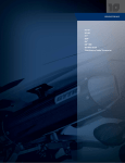
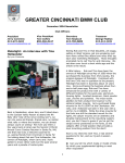
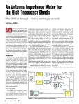
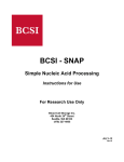
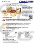
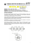
1/29/2009
MOTORCYCLE
M2009-002R
©2009 YAMAHA MOTOR CORPORATION, U.S.A.
RECALL
This modification has top priority. This bulletin must be
performed immediately to ensure customer safety.
2006~2008 and Certain 2009 FJR1300A/AE
FACTORY MODIFICATION CAMPAIGN – Main Switch
Yamaha Motor Corporation, U.S.A. has decided
that a defect which relates to motor vehicle safety
exists in all 2006 through 2008 and certain 2009
FJR1300A and AE model motorcycles. The main
ignition switch’s wire connection could overheat
due to electrical resistance, becoming hot enough
to melt the solder connecting the wire to the main
switch. The wire could come off the switch if the
solder melts, preventing the electrical system from
functioning. If this occurs while the motorcycle is
being ridden, the engine would stall and be impossible to restart which could result in an accident with
injury or death.
MAIN SWITCH
To correct this defect, Yamaha is initiating a Factory Modification Campaign. Affected motorcycles must have
the main switch replaced with a new one designed to prevent overheating.
Yamaha is notifying all registered owners of affected motorcycles by mail. A copy of this letter is included in
this bulletin. The customer should take the letter along with the affected motorcycle to an authorized Yamaha
dealer for the modification.
A computer report listing all affected motorcycles invoiced to your dealership is included with this bulletin. Use
the list to help ensure all motorcycles are modified. All sold motorcycles that have been registered with Yamaha
will show the customer’s name and address. Your dealership must notify the owner of any affected motorcycle
that was actually sold but is listed as “unsold” in the report.
You must modify all affected motorcycles in your inventory as well as all customer-owned motorcycles brought
to you for this service. Any affected motorcycle that you purchase from Yamaha in the future will also require
modification. If you purchase a motorcycle from another dealer, check to see if the procedures in this bulletin
have already been performed before you sell the motorcycle.
Motorcycles that are affected should not be operated until they are modified. It is a violation of Yamaha
policy for your dealership to deliver any affected motorcycles to customers until the procedures in this
bulletin are performed.
When the modification on each motorcycle is performed, follow the Warranty Information section of this bulletin to receive reimbursement. Be sure to use the Factory Modification Campaign procedures in Chapter 7 of
the Warranty and Y.E.S. Handbook (LIT-11760-00-08).
PAGE 1 of 10
Unsold
Units:
Replace the main switch during PDI service, reusing the original key cylinder and key.
Sold Units: Replace the main switch, reusing the original key cylinder and key, according to this bulletin on
all affected units. Check first to be sure the modification has not already been performed (see
Identification Procedure in this bulletin).
Parts:
Yes, order a new main switch kit for each affected unit. See the Parts Information section for
details.
Warranty: Factory Modification Campaign. See the Warranty Information section of this bulletin. This modification applies to all affected units regardless of ownership or warranty status.
Notify
Customers:Yes. You must immediately contact any customer whose motorcycle shows as unregistered on
the enclosed report. Yamaha has sent letters to customers whose motorcycles were registered
for warranty as of 1/28/09.
All 2006 FJR1300A
All 2006 FJR1300AC
All 2006 FJR1300AE
All 2006 FJR1300AEC
All 2008 FJR1300A
All 2008 FJR1300AC
All 2008 FJR1300AE
All 2008 FJR1300AEC
All 2007 FJR1300A
All 2007 FJR1300AC
All 2007 FJR1300AE
All 2007 FJR1300AEC
2009 FJR1300A 2009 FJR1300AC 2009 FJR1300AE 2009 FJR1300AEC RP15E-006050~006392
RP15Y-001047~001108
RP16E-001560~001736
RP16Y-000275~000306
Refer to the service manual as needed when performing these procedures.
2006 and 2007 models: LIT-11616-19-83
2008 models: LIT-11616-21-63
2009 models: LIT-11616-22-73
IMPORTANT:
You will need to have a drill press for this procedure.
Triple Clamp/ Main Switch Assembly Removal
The front of the fuel tank must be raised to access the main switch wire connectors.
1. Place the motorcycle on the centerstand on a level surface. Remove the seats.
PAGE 2 of 10
2. Remove the fuel tank panel. Remove the two
bolts holding the front of the tank. Loosen (do
not remove) the long bolt holding the rear of the
tank. Lift and support the front of the tank as it
pivots on the rear mount.
LOOSEN
THIS
BOLT
FUEL
TANK
PANEL
3. Remove the center support (T-bar) and pull back
the heat protector to access the connectors. Disconnect the red and white connectors.
REMOVING THE T-BAR
4. Set the fuel tank temporarily back into position.
Carefully cover the tank and both sides of the
cowling near the handlebars to prevent damage.
DISCONNECT THE RED AND
WHITE CONNECTORS
5. Remove the upper triple clamp nut and loosen
the two fork clamp bolts (see adjacent photo).
6. The handlebar has three adjustment positions.
Mark handlebar position on the upper triple clamp
with erasable marker so the handlebars can be
returned to their same position for the customer.
Remove the handlebars and hang them carefully
along side the cowling, supported by the cables
and hoses, with padding to avoid damage.
PAGE 3 of 10
7. Cut the zip tie holding the main-switch harness,
then remove the upper triple clamp and main
switch assembly from the motorcycle.
CUT ZIP
TIE
Main Switch Removal
The main switch is bolted to the bottom side of the
upper triple clamp with two 8mm tamper-proof bolts.
The bolt heads must be removed with a series of drill
bits. Follow these procedures closely and carefully
for quick, easy removal of the switch.
CAUTION:
Use extreme care to avoid damaging the top of
the upper triple clamp while drilling the bolts.
You MUST use a drill press to ensure accurate
drilling!
8. Place a punch mark as accurately as possible in
the center of each bolt. An automatic-type punch
works best.
9. Place the upper triple clamp upside down in a
proper drill press vice, using extreme caution
not to damage it. Use sturdy padding to avoid
scratching.
10. Starting with an 1/8" drill bit, drill each bolt, dead
center, slightly deeper than the switch base (approx. 1/2" to 3/4" deep).
11. Repeat step 10 using a 1/4" drill bit.
12. Repeat step 10 again using a 3/8" drill bit. Only
drill deep enough to pop the head off the bolt.
TIP:
If the bolt head does not come off, the hole may not
have been centered properly. Repeat the drilling
again with a one-size-larger drill bit which should remove the head.
PAGE 4 of 10
CENTER
PUNCH
13. Remove the upper triple clamp from the drill
press vise. Using locking pliers (such as ViseGrips®), remove the remainder of the bolts from
the holes. Set the upper triple clamp aside.
Preparing the New Main Switch for Installation
The key cylinder assembly from the old main switch
assembly is reused in the new main switch so the
customer can use the same key as before.
REMOVE REMAINDER OF BOLTS
RUBBER
SCREW
COVER
TAMPER-PROOF
SCREW
14. Remove the rubber screw covers from the lock
cover on the old main switch. Use a 3/8" drill bit
to drill out the two tamper-proof screw heads
holding the lock cover to the main switch. The
lock cover, which will not be reused, acts as a
guide for drilling the screws.
15. Remove the lock cover from the new main switch
by unscrewing the two tamper-proof screws. Remove the key cylinder assembly and spring from
the new main switch. Only the cover will be reused.
DO NOT WORRY ABOUT DAMAGING THE
OLD LOCK COVER; IT IS NOT REUSED
PAGE 5 of 10
16. Carefully remove the key cylinder assembly and
spring from the old lock cover and install them in
the new main switch cover in the same position
as it was in the old switch.
LOCK COVER
17. Install the new lock assembly cover over the old
key cylinder and spring on the new main switch.
Temporarily finger-tighten the new tamper-proof
screws.
18. Check the new main switch for proper mechanical operation, using the original key from the old
main switch. Make sure the key operates smoothly in all positions. If not, remove the spring and
cylinder and reinstall correctly.
19. Tighten the tamper-proof screws until they break
off just above the screw heads. The screws are
designed to break when the proper tightening
torque is reached.
KEY CYLINDER
SPRING
NEW SWITCH
INSTALL OLD
KEY CYLINDER
INTO NEW MAIN
SWITCH
OLD SWITCH
(DISCARD NEW
KEY
CYLINDER)
DISCARD
OLD
LOCK
COVER
20. Install the new rubber covers over the tamperproof screws.
21. Remove the “red circled” protective cover from
the top of the main switch. The new main switch
is now ready to be installed on the upper triple
clamp.
Installing the New Main Switch
22. Be sure the plastic main switch cover is still
installed properly in the upper triple clamp.
SWITCH
COVER
PAGE 6 of 10
23. Apply blue Loctite® 242 to the new tamper-proof
bolts and install main switch in the upper triple
clamp. Tighten the bolts until the heads break off,
indicating proper torque has been reached.
NEW
BOLT NOT
TORQUED
YET
NEW BOLT
PROPERLY
TORQUED
CAUTION:
Be sure to hold the upper triple clamp securely and with proper padding so it will not be
scratched during the tightening procedure.
Reassembly
24. Reinstall the upper triple clamp and handlebars
in the reverse order of removal. Install the new
zip tie supplied in the kit in the same location as
the one that was cut off.
Be sure to tighten all hardware to the proper
torque.
Steering stem nut: 115 Nm (11.5m-kg, 85 ft-lb)
Upper bracket pinch bolt: 26 Nm (2.6m-kg, 19 ft-lb)
Handlebar bolt: 23 Nm (2.3m-kg, 17 ft-lb)
Handlebar nut: 65 Nm (6.5m-kg, 47 ft-lb)
INSTALL
NEW ZIP
TIE
25. Connect the red and white connectors from the
main switch harness to the main harness.
26. Reposition the heat protector, and then reinstall
the center support (T-bar).
Center support mounting bolts: 37 Nm (3.7m-kg,
27 ft-lb)
27. Reinstall the fuel tank and tighten the mounting
bolts.
Front fuel tank mounting bolts: 10 Nm (1.0m-kg,
7.2 ft-lb)
Rear fuel tank mounting bolt: 16 Nm (1.6m-kg, 11
ft-lb)
28. Confirm that the main switch works properly in
each position.
29. Move the handlebars from lock to lock, while
checking for proper clearance and routing of all
cables and hoses.
30. Tag and hold the old main switch for 90 days from
the date you submit your Recall Reimbursement
Request. Put a punch mark on the frame number
as described in Identification Procedure in this
bulletin.
PAGE 7 of 10
When the modification is complete, put a punch mark next to the Primary ID as shown. Check for this punch
mark if you encounter an unfamiliar unit. You can also check unit status on YDS or by contacting your Regional
Technical Advisor.
PUNCH MARK HERE
*
JYARP15E66AOOOOOO
A new main switch can be identified by the yellow band on the harness near the connectors.
PREVIOUS
Part Number
Description
90891-30058-00
FJR1300 Key Set Kit
Kit Includes:
• Main Switch Assembly
• Anti-theft bolts, 8mm x 2
• 100mm Clamp (“zip tie”)
• Rubber Screw Covers x 2
PAGE 8 of 10
NEW
Dealer Cost
$35.71
The owner of each warranty-registered unit will receive a letter announcing this campaign. The customer’s
letter includes the Primary ID and Recall Number.
The modification is authorized for all motorcycles, both sold and unsold, regardless of ownership or warranty
status. You do not need the customer’s letter to perform the modification or to file for reimbursement.
Submit a Recall Request for the parts and labor for the main switch exchange as described below using Recall
Number 990051. Choose the status “M.” You will be reimbursed for the Main Switch Steering Lock plus labor.
The labor allowance is 1.0 hour, which includes an allowance for the small amount of Loctite® used.
YDS:
When signed on to YDS, click on the Service Tab, and then “Recall Request-Add.” This function will allow you
to enter multiple Primary IDs for the same recall. Remember that YDS requires a 7-digit serial number, so use
a “0” as the first digit. The system will check your submission instantly to make sure the Primary ID numbers
you’ve entered are valid for the recall. You can check back the next day for your claim numbers to track your
credit.
MAIL:
Complete a recall Reimbursement Request (LIT-11790-00-03) as shown below:
Recall Number
9 9 0 0 5 1
R P 1 5 E
0 0 0 6XX X
0 1
3 1
2 0 0 9
If you have any questions about proper procedures for Factory Modification Campaigns, see Chapter 8 in
your Warranty and Y.E.S. Handbook (LIT-11760-00-05).
PAGE 9 of 10
January 29, 2009
SAFETY RECALL NOTICE
Dear Yamaha Owner:
This notice is sent to you in accordance with the requirements of the National Traffic and Motor Vehicle Safety Act. Yamaha Motor
Corporation, U.S.A. has decided that a defect which relates to motor vehicle safety exists in all 2006 through 2008 and certain
2009 FJR1300A and AE model motorcycles. Our records show that you own the affected motorcycle shown above.
In affected motorcycles, the main ignition switch’s wire connection could overheat due to electrical resisThe reason for this recall:
tance, becoming hot enough to melt the solder connecting the wire to the main switch. The wire could
come off the switch if the solder melts, preventing the electrical system from functioning. If this occurs
while the motorcycle is being ridden, the engine would stall and be impossible to restart which could
result in an accident with injury or death.
What Yamaha
and your dealer
will do:
To correct this defect, affected motorcycles must have the main switch replaced with a new one designed
to prevent overheating. Your current key will still work in the new main switch. There will be no charge
to you for this procedure. Replacing the main switch takes about 1 hour, but your dealer may need to
keep your motorcycle longer depending upon their schedule.
What you should
do now:
Please call your Yamaha dealer to make a service appointment to have this procedure performed. Remember to take this letter with you when you take in your motorcycle.
You should not ride your motorcycle until this modification is performed.
If you are unable to return to the Yamaha dealer who sold you the motorcycle, this service will be performed
by any authorized Yamaha Motorcycle dealer. For the name of a dealer near you, call 1-800-88-YAMAHA
or visit the Yamaha web site at: www.yamaha-motor.com.
Federal regulations require that any vehicle lessor receiving this recall notice must forward a copy of this
notice to the lessee within 10 days.
If you need help:
If, after contacting your dealership, you have questions or concerns which the dealership is unable to
answer, please write to:
Yamaha Motor Corporation, U.S.A.
Customer Relations Department
P.O. Box 6555
Cypress CA 90630
or call 1-800-962-7926.
If, after contacting Yamaha Customer Relations, you are still not satisfied that we have done our best to
remedy the situation without charge and within a reasonable time, you may submit a written complaint to
the Administrator, National Highway Traffic Safety Administration, 1200 New Jersey Avenue, SE., Washington, DC 20590; or call the toll-free Vehicle Safety Hotline at 1-888-327-4236 (TTY: 1-800-424-9153); or
go to http://www.safercar.gov.
If you no longer
own this Yamaha:
If you have sold your motorcycle to another party, please call us toll-free at 1-800-962-7926 with the name
and address of the new owner, along with the serial number shown above your name on the address
label above.
We’re sorry to cause you any inconvenience, but we are sincerely concerned about your safety and continued satisfaction with
our products. Thank you for giving your attention to this important matter.
Sincerely,
Customer Support Group
Yamaha Motor Corporation, U.S.A.
PAGE 10 of 10