1
Flyin' Miata
FM turbo kit
installation instructions
22-1XXXX
Flyin’ Miata
499 35 Rd, Palisade, CO 81526
tech line: 970.464.5600
www.flyinmiata.com
Introduction
Thank you for purchasing the Flyin’ Miata turbo system. We regard the installation as a mutual project and will be pleased to offer help at any time. We remain committed to make this a successful and
enjoyable experience for all concerned. These instructions will offer the installer a guide for the installation and operation of the Flyin’ Miata turbocharger system for the first and second generation ('90 '05) Mazda Miatas. Any instructions that don't apply for all years are clearly marked.
STOP!
DO NOT DEVIATE FROM OR SKIP ANYTHING IN THESE INSTRUCTIONS UNLESS YOU TRULY UNDERSTAND EVERYTHING ABOUT WHAT YOU’RE DOING. WHEN IN DOUBT, CALL US.
INCORRECT DEVIATION COULD BE A VERY EXPENSIVE MISTAKE.
Please read through these directions entirely. Evaluate your own skills honestly and decide whether
this installation is something that you are comfortable doing. Realize that you are doubling the horsepower of your car and the consequences of improper installation could destroy your engine. To install
this kit safely, you must have a firm grasp of how cars work. Proper tool use is critical. We are more
than willing to help anyone install this kit, but you must be honest with yourself with respect to your
skill level before you jump into the deep end. These directions do give you a step-by-step process
to follow, but problem solving and critical thinking are still required. If you have any concerns, either
discuss the process with us or pay a professional to do the installation.
We know there are a lot of words in this manual - we’re sorry, but they’re all very important words.
PLEASE READ EVERYTHING. Don’t skim, actually read the entire thing - before you start the installation. We’re happy to help, but we’d rather not read the instruction manual back to you.
The success of this installation will be determined by a variety of factors. The vehicle must be in
excellent condition and in proper tune prior to starting the installation. Do not attempt to install this kit
on a car that is not running properly. Before installation, fix any problems. This will help prevent our kit
getting blamed for pre-existing conditions. Care and attention to detail by the installer are of extreme
importance. The daily operator of the vehicle must observe all operational guidelines. For specific
torque values, refer to the service manual that’s called out in the “Tool and Equipment Requirements”.
Use high-temp anti-seize on any bolts that don’t specifically call for other thread treatments.
Inventory all the components when the kit arrives. We strive to ensure all the components are included in the kit, but if a part is left out you will want to know it before you are looking for it during the
installation. Plus, this will allow you to familiarize yourself with the parts in the turbo kit.
Prior to starting the installation, go through two tanks of the highest octane fuel available. Do not
dilute with lesser octane fuel already in the tank. If necessary, drain the tank. Using lower octane fuel
will result in knock that could damage the engine.
All left or right directional references are from the driver’s viewpoint. If clarification of these instructions is required, please contact us at 970-464-5600 or via e-mail at [email protected]. Suggestions for improvements of these instructions are welcome. Please make notes on the instruction set
and mail to: Flyin’ Miata, 499 35 Rd, Palisade, CO 81526.
These instructions and the operational requirements for this system must be reviewed with the driver.
Flyin' Miata
970.464.5600
2
Rev 6.3
Contents
Introduction................................................................................ 2
Tool and Equipment Requirements........................................... 4
Section 1: Parts Inventory........................................................ 5
Section 2: Disassembly............................................................ 7
Section 3a: Slot frame rail lip (small / normal turbos)............. 10
Section 3b: Slot frame rail lip (big turbos)...............................11
Section 4: Oil Return Line...................................................... 12
Section 5a: Oil Supply Line for '90 - '95 Cars......................... 13
Section 5b: Oil Supply for '96 - '05 Cars................................. 14
Section 6: Assemble Manifold, Turbo, and Outlet.................. 15
Section 7: Mount Turbocharger Assembly.............................. 16
Section 8: Oil Lines .............................................................. 21
Section 9: Water Lines........................................................... 22
Section 10: Mount Intercooler................................................ 23
Section 11: Re-routing coolant............................................... 25
Section 12: Install Fuel Injectors (FMII and FMIIR -only)....... 26
Section 13: Intercooler Tubes................................................. 28
Section 14: Compressor Inlet................................................. 30
Section 15: Trim Mouth/Radiator Inlet Duct............................ 33
Section 16: Trim Splash Pan.................................................. 35
Section 17: ECU / Vacuum Line Connections........................ 39
Section 18: Miscellaneous...................................................... 41
Section 19: Heat Shield ......................................................... 43
Section 20: Boost Control....................................................... 44
Section 21: General Rules of Operation................................. 46
Section 23: Maintenance........................................................ 46
Flyin' Miata
970.464.5600
3
Rev 6.3
Tool and Equipment Requirements
Every project on your Miata presents the opportunity to purchase more tools. Below are the tools you
will need for the successful installation of this turbo kit.
metric open/box end wrenches
metric socket set clean rags
assorted slot and Phillips screw drivers metric allen wrenches
teflon thread sealant paste (NOT tape)
floor jack jack stands x 4
one quart of mineral spirits
hammer
JB Weld (optional)
eye protection
grease
funnel
long (18”+) extension (optional)
high-temp anti-seize
oil filter and fresh high quality synthetic oil
spray can of cleaning solvent
hacksaw
hand drill with ½” chuck
silicone sealant (“The Right Stuff” is best)
Loctite (blue)
factory shop manual or equivalent
duct tape
Penetrating oil (“PB Blaster” is best)
marker/paint pen
touch up paint/nail polish
electrical tape
razor blade
vise (optional)
universal joint (for your ratchet) (optional)
Preliminary
1. Again, be sure that the car is running properly and all of the maintenance is up-to-date.
2. Raise the car and support with jack stands. NOTE: If you’re installing new fuel injectors - which
come with an FMII - go to page 36 to relieve fuel pressure while the car is still “in one piece”.
3. Drain the coolant. There is a drain plug in the center of the bottom of the radiator.
4. Drain the motor oil. Install the new filter (NOT the new oil) and temporarily reinstall the drain plug.
5. Disconnect the battery.
6. DON’T OVERSPIN THE TURBO! Carefully spinning it by hand is okay, but shooting an air nozzle
from an air compressor at the impeller isn’t. The turbo can handle very high rpm with oil pressure
(i.e., when the car is running), but without oil pressure you will permanently damage the turbo.
Acronyms:
IAC - Idle Air Control (valve)
O2 - Oxygen (sensor)
WBO2 - Wideband Oxygen (sensor)
ECU - Electronic Control Unit (computer)
AFM - Air Flow Meter (‘90 - ‘93 cars only)
MAF - Mass Air Flow (sensor) (‘94 - ‘05 cars only)
MAP - Manifold Absolute Pressure (sensor) (standalone ECUs only)
BOV - Blow-Off Valve (or bypass valve)
NA - ‘90 - ‘97 Miatas
NB - ‘99 - ‘05 Miatas
NPT - National Pipe Thread Taper
Flyin' Miata
970.464.5600
4
Rev 6.3
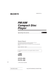
Section 1: Parts Inventory
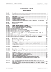
Below is a picture of all of the parts included in a FMII Hydra. Keep in mind that the kit you purchased
could be different (or newer!). There’s a list of what most of the items are on the following page. The
parts are listed by the order the appear (and are numbered) in the picture, not necessarily by relation.
3
4
2
7
5
1
6
9
10
11
15
8
14
12
13
18
16
17
23
22
26
25
21
20
19
24
34
27
28
32
33
29
30
Flyin' Miata
970.464.5600
5
31
Rev 6.3
1. Serial cable and WBO2 cable. For use with the Hydra only, not included with Voodoo kits.
2. Oil feed line (Bag 4X, 22-8002X). The line for ‘90 - ‘95 cars will be much shorter.
3. Intake air temperature sensor (07-47200)serial. For use with the Hydra only, not included with Voodoo
kits.
4. 1-1/4” heat sleeve (36-90960), for use with the oil drain hose (now black).
5. Hydra wiring harness (07-17905). For use with the Hydra only, not included with Voodoo kits.
6. Boost gauge (23-161X0). This is an old gauge, the new gauges look somewhat different.
7. 5/8” heat sleeve (36-90970). For use with the water lines. It will need to be cut in half, as will the water lines (also now black).
8. Gauge pod (21-165XX). A dual gauge pod could have been substituted for the single gauge pod.
9. Fuel injectors (04-410XX). Not included with Voodoo kits, the stock injectors are reused there.
10.Exhaust clamp and gasket, to be used with the new downpipe. The gasket is used at the cat.
11.Hydra wideband O2 sensor (WBO2) (06-99150). For use with the Hydra only, not included with Voodoo kits. The AEM gauge/wideband we sell for Voodoo kits has a simlar sensor but other parts are
different.
12.Exhaust manifold (should be black) (22-210XX).
13.Downpipe (22-46XXX). There are two pieces to the downpipe, the exhaust clamp holds them together.
14.Hydra ECU (07-17000). Included with FMII Hydra kits only, not included with Voodoo kits.
15.Compressor inlet (22-504XX). Current parts look a bit different.
16.Blow-off/bypass valve (BOV) (05-9012X).
17.Throttle body inlet elbow (22-50310). Current parts are combined with the throttle body junction pipe
(27) and look different.
18.Air box (22-601XX). The one pictured is for 99+ cars, earlier cars will have a different (but similiar)
design.
19.Heat shield (02-20560). This is installed over the turbo.
20.Turbo (02-70XXX). Be aware that because of the shape of some of the bosses that need to be removed for our purposes, some hand grinding needs to be done. This can sometimes appear a bit
“rough”, but doesn’t change the functionality.
21.Hydra mounting clip (07-17110). This one is for ‘01 - ‘05 cars, the ‘99 - ‘00 version is very similar, the
‘90 - ‘93 version is somewhat similar, and the ‘94 - ‘97 version is different.
22.Intercooler-out hose (22-50200). This goes between the intercooler and the throttle body junction
pipe.
23.Oil drain hose (also now black) (Bag 5X, 22-8003X).
24.Weather stripping for the air box (36-90050).
25.Outlet (this one’s now black too!) (22-20100).
26.Compressor outlet hose (22-501X0). This connects the turbo and the intercooler.
27.Throttle body junction pipe. Current parts are combined with the throttle body inlet elbow (17) and
look different.
28.Air filter (All FMIIs and 94-05 Voodoo kits: 05-16060, 90-93 Voodoo kits: 05-16070).
29.Water line (Bag 3X, 22-8001). This will need to be cut into two pieces, as there are two lines (in and
out) for the turbo.
30.Air filter mount pipe (22-40210). FMII kits only, not included in Voodoo kits, as the MAF / AFM takes
its place.
31.Check valve (36-90010). This is used for the vacuum lines going into the charcoal canister and the
cruise control.
32.Constant torque hose clamp. These have four washers stacked underneath the hex that’s used to
tighten the clamp. These hose clamps are tight when the four washers bottom out on each other - it’s
important that the clamps aren’t tightened beyond this point.
33.Winzer hose clamps. There are more basic and have a blue collar over the tightening screw.
34.T-bolt hose clamps. These are pretty tough, and are differentiated by the “T” shape of the bolt that’s
used. The “T” portion is opposite the nut.
Flyin' Miata
970.464.5600
6
Rev 6.3
Section 2: Disassembly
NOTE: If you’re removing the transmission anyway, it’s typically easier to install the EGR tube while
the transmission is out. You should install the turbo at the same time, as the EGR needs to be fastened at both ends (exhaust and intake manifolds) at the same time.
1. Remove the dipstick from the dipstick tube. You
don’t need to remove the dipstick tube. You won’t
actually need to do anything with the dipstick, but
there’s a good chance that it could be accidentally broken during the installation. Plug the hole to
ensure nothing slips down there.
2. Remove the entire intake assembly, including the
intake snorkel, air filter box and the crossover pipe
between the MAF / AFM and the throttle body. The
IAC hose won’t be reused but also needs to be
removed. The IAC hose is the small hose that runs
from the IAC (underneath the throttle body) to the crossover pipe.
3. '90- '97 Cars Only: Remove the metal bracket that supports the air box from below and the stud
(in the picture above) that locates it on the outboard side.
4. '90 - '97 Cars Only: If so equipped, remove the cruise control unit from the inner fender and remove the gold colored brackets that mount the unit to the car - these brackets will not be reused.
Do not disconnect the cable! Set the unit in the area below the windshield until we are ready to
mount it again.
5. Voodoo Kits Only: From the air filter box, remove the mass air meter (MAF) / air flow meter
(AFM). This is reused on Voodoo kits, but not on FMII kits. Do not touch the sensing element on
the MAF (the AFM works with a flap / door, and isn’t as sensitive).
6. ‘99 - ‘05 Cars Only: Remove the intake air temperature sensor, and the rubber grommet for the
air temperature sensor. Remove the plastic divider that holds the two relays. Let the relays hang
loose for now, they will be remounted later.
7. Remove the rubber/chrome hose that runs from the driver’s side of the cam cover to the intake
pipe. It will not be reinstalled so the two retaining clips/bolts can be removed from the front of the
cam cover as well.
8. Remove the exhaust manifold heat shield. These bolts will be old and rusted in place, so soak
them down with penetrating oil before trying to remove them. We don’t reuse them, so it’s not
catastrophic if they break. After the heat shield is off, spray the nuts that hold the manifold to the
head and the oxygen sensor with penetrating oil. We will be reusing these parts, so be careful with
them. The studs will often come out of the head, as opposed to the nuts coming off of the studs. If
this happens, try to remove the nut from the stud. Soak in penetrating oil as long as possible, then
grip the stud at the shoulder and remove the nut. The double-nut method (section 6, step 2) can
be used if you have appropriately sized nuts (M10x1.25).
9. Remove the oxygen (O2) sensor from manifold - penetrant is a good idea here as well. Be careful
removing it, as it will need to be reused.
Flyin' Miata
970.464.5600
7
Rev 6.3
10.Before removing the exhaust manifold,
bend the water bypass tube (located
beneath the manifold, running to the
outboard heater hose) back toward the
firewall as far as possible (as shown).
Use a large prybar, prying against the
manifold.
11.Remove the exhaust manifold. Save the nuts, they
will be reused to mount the cast manifold for the turbo. Plug the exhaust ports with rags.
12.Remove the lower splash pan and the black radiator inlet duct/mouth. The splash pan and mouth
will need to be trimmed to fit around the intercooler and reinstalled.
13.Remove the bracket from the bellhousing that supported the factory downpipe. Re-install the bellhousing bolts. The bracket will not be reused.
14.‘01 - ‘05 Cars Only: Remove the under car bracing to allow access to the exhaust. Pay attentiong to the different bolt holes in the brace, as some are slotted, to ease installation. Therefore,
it’s not necessary to fully remove the nuts on those studs.
15.Remove the radiator hose between the lower ouGood tlet in the radiator and the inlet on the block.
On ‘90 - ‘97 cars, there’s a metal pipe between two rubber hoses, this needs to be removed as
well.
16.The pictures below show the parts that will need to be removed from the different cars. Keep in
mind that there may be extra parts in the picture, relative to your car and the kit purchased. For
example, not all ‘90 - ‘97 cars will have cruise control to remove the brackets from and Voodoo
kits retain the factory injectors. If necessary, the fuel injectors will be removed according to the
ECU instructions. Some parts might be slightly different, as Mazda changed things throughout
the years. For example, some
of the fuel injectors will be a
‘90 - ‘93
different color. For Voodoo kits,
you’ll need to retain the MAF
/ AFM that’s shown in these
pictures.
Flyin' Miata
970.464.5600
8
Rev 6.3
‘94 - ‘97
‘99 - ‘05
Flyin' Miata
970.464.5600
9
Rev 6.3
Section 3a:
Slot frame rail lip (Voodoo, Voodoo II, FMII (except 3071 turbo), no electronics
kits only)
The orientation of the compressor on the turbocharger makes it necessary to slot the frame rail lip on
the left side of the car. While this might sound intimidating, it's a simple process. Refer to the picture
to get an idea of what the slot will look like and to clarify any dimensions specified. This method,
versus one in which all three edges are cut, is used to preserve as much frame integrity as possible.
Once the slot is done, finish the raw edges of the slot with some touch-up paint. If none is available,
clear nail polish is a good way to protect the bare metal without worrying about matching colors. Be
sure that the exhaust ports are plugged securely, we want to keep the metal shavings / dust created
out of them.
1. Cut two slits into the frame rail lip, running from right to left (passenger side to driver’s side, up
and down on the picture below). The slits need to be approximately 5/8” long. They need to run
up to, but not through, the face of the frame going straight down. If you feel around underneath
the edge of the frame rail lip, you’ll feel the vertical face of the frame rail itself. The first cut will be
3-1/4” off of the forward shock tower brace, the second cut will be 2-1/4” from the first (towards the
front of the car), or 1” off of the forward shock tower brace. For the small GT2554R turbos, the slot
needs to be longer. Instead of making your second cut at 3-1/4”, it should be made at 4-1/4”.
2. Using a hammer, beat the tab between the two slits down and out of the way. This is a good place
to release any pent-up anger. The farther down you’re able to get the tab, the better.
3. Once the tab is bent out of the way, finish the edges and points of the two cuts. The smoother the
finished slot is, the better it looks and the less likely it is to draw blood.
Shock Tower
Flyin' Miata
970.464.5600
10
Rev 6.3
Section 3b:
Slot frame rail lip (3071 FMII and FMIIR kits only)
If you don’t know what a 3071 or FMIIR is, this doesn’t apply to you
The orientation of the compressor on the turbocharger makes it necessary to slot the frame rail lip on
the left side of the car. This needs to be a deeper slot than what’s described on the previous page.
Refer to the picture on the previous page to get a general idea of what the slot will look like and to
clarify any dimensions specified. The turbos we use on the FMIIR are pretty big, so you’ll need to cut
a fairly large slot. For this reason, we include a weld-in plate (22-62000C). Please be sure to match
our dimensions as closely as possible, as this will make our plate fit best. Be sure that the exhaust
ports are plugged securely, we want to keep the metal shavings / dust created out of them.
1. First, you’ll want to scribe out your dimensions. From where the vertical face (that connects to
the shock tower) would intersect the edge of the frame rail, measure 3/8” towards the firewall and
make a mark (this is the 1” dimension in the picture on the previous page). Now measure another 4-1/4” from that mark (4-5/8” from the vertical face) and make another one (this is the 3.25”
dimension in the previous picture). Scribe another line that’s parallel to the edge of the frame rail
and 1-1/4” closer to the left shock tower. Make two marks on that line, one that’s 1” from the original vertical face (same as the picture on the previous page) and one that’s 3” from that mark (4”
from the vertical face, same as 3.25” dimension in the previous picture). Now draw a diagonal line
that runs from the marks you just made (1” and 4” from the vertical face) to the original marks (3/8”
and 4-5/8” from the vertical face). That’s the template for the top cut. Now run 1” down (vertically)
the vertical face on the frame rail (which runs fore and aft) and make marks that line up with the 1”
and 4” marks made in the second step. Connect those two marks, then trace a line diagonally up
to the 3/8” and 4-5/8” marks.
2. Cut along the lines you just scribed - a cut-off wheel should work well. Try to make all of the cuts
as straight as possible, as you’ll be welding our plate where you made the cuts. Look at the shape
of the plate and make sure that the hole you’ve cut matches it.
3. Weld the plate in (your battery is disconnected, right?), then paint it to protect it from rust (both the
plate and the exposed edges in the car will rust otherwise). You can try to get it close with off-theshelf paint, or some automotive shops (such as NAPA) will mix a spray can of paint to your specific color.
Flyin' Miata
970.464.5600
11
Rev 6.3
Section 4: Oil Return Line
Bags to use: #2A, #5A
Drilling and threading a hole in the oil sump is a perfectly safe process. Should any shavings slip
through, they will find it very difficult to get off the bottom of the sump and into the oil pickup. For rubber drain lines, the drain hole location is 2” below the upper lip (no lower!) and as far forward on the
left side of the sump as possible, directly under the A/C compressor bracket (if so equipped). See picture below. For the FM hard oil drain line (optional), the drain hole location will be determined by the
location of the hard line after it and the turbo are mounted (but should be very similar). See the separate instructions for the hard lines. If you have compressed air that you can regulate, set the pressure
to 5psi and connect a hose to the valve cover breather on the left side of valve cover. Drill until the bit
just breaks through, then up pressure to 10psi. Keep the air blowing while you drill and tap the hole.
DO NOT use pressure over 10psi at any time. More pressure will blow the seals out of the engine!
Be sure to wear eye protection as the aluminum shavings will be blowing out of the oil pan.
1. The hole needs to be drilled with the supplied .578”
(37/64”) diameter bit. It may be easier to start with
a smaller drill, then work up to the larger bit. STOP
DRILLING AS SOON AS YOU BREAK THROUGH!
It is possible to hit the oil pick-up tube if you continue
through. This is “not a good thing”, as it will cause loss
of oil pressure. A good way to stop the bit from going
too far is to wrap the bit with a few layers of masking,
electrical, or duct tape about 1/4” from its end. Try to
get the drill as straight as possible, but it’s okay if it’s
angled slightly. It’s very important for the tap to go in
straight, however.
2. Keeping the compressed air running, tap the threads with
the supplied 3/8" NPT tap. Measure the distance from the
surface of the drilled hole to the closest edge of the pickup
tube, then wrap tape around the tap at a distance a 1/4”
less than what you measured from the end of the tap. This
will ensure that the threads are completely cut, but the tap
is still far enough away from the oil pickup. Grease the tap
to help collect the shavings. Use a socket and extension to spin the tap. Again, make sure that the
tap goes in straight. Do this by hand - spin it in by hand a couple turns, back it out one turn, and
repeat.
3. Clean the surfaces as thoroughly as possible, using a thinner or something similar. Otherwise the
adhesive used in the next step won’t stick.
4. Put JB Weld epoxy or silicone sealant on the threads of the 3/8NPT -> 5/8” hose barb (36-50020)
and screw it in tightly. Grease the inside of the 5/8” hose (36-40231) and slide it onto the fitting.
Route the hose upward so that it can be accessed from the engine compartment.
5. Remove the oil drain plug and place a clean catch pan under the oil sump. Attach a funnel to the
top of the hose and pour the mineral spirits down through the hose to clean out shavings.
6. Allow the solvent to drain for approximately 15 minutes before replacing the sump plug. Remove
the hose from the sump and set it aside for later use. If the hose is difficult to remove, cut it at the
barb. The length of the hose is a few inches longer than necessary.
Flyin' Miata
970.464.5600
12
Rev 6.3
Section 5a: Oil Supply Line for '90 - '95 Cars
Bag to use: #4A
The oil supply system is the lifeblood of the turbo. When running the oil supply line make sure that
there aren't any sharp bends, and it is clear of heat sources. The oil supply will tap into the oil galley
on the left side of the engine block. Alternatively, if our oil filter relocation kit is installed on the car
that can be used as an oil source (a longer hose will be required, contact us). Follow the directions
included with the relocation kit. Regardless of what you use as a source, do NOT use teflon tape on
any of the oil lines (or fuel lines, for that matter). A small piece could get into the oil passages and
clog them, which is definitely a bad thing.
1. There is an unused oil galley on the left side of the engine block down close to the bell housing.
Remove the plug. This is a 14mm bolthead.
2. Install the oil line adapter fitting (27-12365) into the galley at the position shown. Use the crush
washer.
3. Add one of the 90-degree swivels to the fitting (27-12467). Tighten with the swivel pointed forward.
4. Attach the braided hose (27-32105) to the fitting and tighten. Cover the other end with a small
plastic bag and let it hang loose for now.
Flyin' Miata
970.464.5600
13
Rev 6.3
Section 5b: Oil Supply for '96 - '05 Cars
Bag to use: #4B
The oil supply system is the lifeblood of the turbo. When running the oil supply line make sure that
there aren't any sharp bends, and it is clear of heat sources. The oil supply will tap into the oil galley
at the oil pressure sensor located under the intake manifold between cylinders #2 & #3 above the oil
filter. Alternatively, if our oil filter relocation kit is installed on the car that can be used as an oil source.
Our oil filter relocation system does make sourcing the oil quite a bit easier on a 96-05. Follow the
directions included with the relocation kit. Regardless of what you use as a source, do NOT use teflon
tape on any of the oil lines (or fuel lines, for that matter). A small piece could get into the oil passages
and clog them, which is definitely a bad thing.
1. Remove the oil pressure sensor using a 15/16”
socket.
2. Put the 1/8NPT tee in a vice and attach the oil
fitting(36-50200). The side without the internal
chamfer / bevel goes into the block, the side with
the chamfer / bevel goes into the tee. The (slightly - ~.020”) larger diameter side goes into the tee,
if you need a double-check). The supplied copper
washer goes between the fitting and the block, not
the fitting and the tee. Next, add the oil pressure
sender as shown to the right. Do not use Teflon
tape here (or anywhere) as a small piece of it
could find its way into the oil system and plug up an oil passage. Instead, use a small amount of
sealant on the threads (no sealant on the first couple of threads though). Do not add the union,
27-12255 (incorrectly labeled as 36-50160 in the picture), now as it will be installed after the assembly is in the block. Since these fittings have tapered threads, they don’t have a specific torque
value. Make sure they’re snug, but you’ll
have to be the torque wrench here.
3. Thread this assembly into the engine block, again using sealant on the
threads (as described above). Be sure
to thread it into the hole shown in the
picture. An easy way to be sure you
have the right hole without being able
to see it is to feel how close it is to the
freeze plug. When tightening the assembly, make sure the port for the union
faces aft. Once the assembly is tight,
thread the adapter (27-12255) into the
tee. The union needs a small amount of
thread sealant on the union side, but not
on the hose side.
4. Connect the oil supply line (27-32280)
to the union and run it up to the top of the engine (again, NO sealant here). Cover the end with
a small bag for now. Note: The intake manifold has been removed for a clearer picture. It is not
necessary to remove it for installation of the oil fitting.
Flyin' Miata
970.464.5600
14
Rev 6.3
Section 6: Assemble Manifold, Turbo, and Outlet
This only applies to those who haven’t opted to have us assemble the manifold, turbo, and outlet. If
those pieces are separate in your kit, follow these directions. If they’re assembled, ignore this page.
No gaskets are used between the manifold and turbo, turbo
and outlet, or outlet and downpipe. If you use a gasket in
any of these locations, it will just fail and you’ll have to take
everything apart to remove it. All of our pieces are machined
flat (the downpipe actually has a slight dome to enhance the
seal), so they will seal once tightened down.
1. All of the non-Inconel hardware here should be torqued
1
to 16 ft-lbs / 190 inch-lbs. The Inconel studs should be
torqued to 24 ft-lbs / 290 in-lbs.
2. First, install the included studs. Be sure that the non-Inconel studs
(36-10331) are installed such that the nut will ultimately be installed
on the long end. The Inconel studs (36-10339) are symmetrical, so
2
that’s a non-issue. If you purchased the Inconel studs (good call!),
they go into the manifold (the stainless studs are used for both
sides of the outlet). Use two M8 x 1.25 non-locking nuts (36-20240),
tightened against each other, as a surface for your wrench (1), so
that you can tighten them down. Once the stud has been tightened
down, loosen the top nut while holding the bottom nut, remove both
nuts, then move on to the next stud. Install the studs in the manifold, turbo, and outlet.
3. Bolt the turbo onto the manifold. Don’t expect to be able to get a
torque wrench on all of the hardware, it won’t be possible for most.
Just make a close approximation of 16 or 24 ft-lbs. Do get the
hardware snug, but don’t go crazy. If you’re using Stage 8 hardware
(36-00000), tighten the nut, then slip the tab onto the nut as shown
(2). You want to position it such that if the nut tries to loosen, the tab
will interfere with something - in the picture, you can see that the
3
tab will interfere with the turbine housing if the nut loosens; be sure
to do something similar on all of the nuts. Once the tab has been
properly positioned, snap the E-ring into the groove for the nut.
4. Now slip the outlet over the studs on the turbo. While you’re holding
that in place, move the wastegate arm (you’ll have to remove the
actuator from the arm) to ensure that the wastegate door can sufficiently open - it shouldn’t catch on the outlet. You want it to point
not-quite straight back when it stops, as shown (3). This was an
occasional problem with previous suppliers, but not with our current
supplier, but it’s still good to double-check. Be sure that the face of
the end of the wastegate rod is parallel to the face on the wastegate itself (3). Be careful when
you remove the C-clip, they seem to be allergic to humans and like to run away. Holding a magnet
close is a good idea.
5. Bolt the outlet onto the back of the turbo. Again, you probably won’t be able to use a torque
wrench here.
Flyin' Miata
970.464.5600
15
Rev 6.3
Section 7: Mount Turbocharger Assembly
Bag to use: #3A, #5A
The turbocharger, exhaust manifold and turbine outlet casting should now be one piece (having been
assembled by you or us. This complete assembly will be mounted onto the engine. The assembly will
look like the photo below with the standard oil and water lines. If you’re using our hard lines, ignore steps 1 - 5 and follow the hard line instructions. Then come back to these instructions and start with step 6.
1. GT2554R only: Bolt the aluminum adapter (22-60020) onto the compressor (silver half of the turbo) outlet.
2. Bolt the aluminum adapter (02-70501) onto the bottom of the turbo with
the gasket (02-70510) smeared with sealant in between it and the turbo
(1). Then thread the hose barb (36-50020, with thread sealant on the
threads) into the fitting and tighten it.
3. Lubricate the inside of
the 5/8” oil drain line (361
40231) with grease/oil.
Slide the oil drain hose
onto the middle fitting on
the bottom of the turbo.
Cover the top of the hose
with larger heat shield
sleeve (36-90960). Secure
the hose with the 14274mm hose clamp (3670005).
4. Add the water hoses (3640120) to the turbo. The
inboard (closer to the
engine) hose should
be 30” long and the
outboard (closer to
the fender) hose 36”
long. We include one
66” length of hose, cut
it accordingly. You’ll
need to push each
hose onto the banjo
fitting (02-70520, hose
barb), then slip them
onto the banjo bolt
(02-70525). Be sure to
place a crush washer
(04-38015) on either
side of the banjo fitting
while installing them onto the turbo. Try to orient the hoses so that their natural curve points them
towards the front of the engine. Slip the heatshield up as far as possible, and secure the hose and
heatshield with the 3/8” hose clamps (36-70202). The outside banjo fitting should be left loose, it
will be removed after the next step.
Flyin' Miata
970.464.5600
16
Rev 6.3
5. Standard Turbo (GT2560R) Only: Using the supplied 3/4” loom clamps (36-70500), secure the
water lines to the gold or silver bracket attached to the compressor housing on the turbo. Be sure
that the loom clamps are oriented so that the bolt is above the water line, as in the picture. Again,
the loom clamps need to go around the hose and heat shield. Be sure that the lines don’t have
any kinks in them, aren’t too tight, and aren’t too close to the exhaust manifold. The inboard line
will go to the upper mounting point (2), the outboard line will go to the lower mounting point (3).
The picture shows the turbo assembly already mounted on the engine, however, the bracket for
the water lines is easier to access before the assembly is mounted. Once both water lines have
been secured to the bracket, the outboard line will need to be pulled off of the turbo. Leave the
line on the banjo fitting, and remove the banjo fitting from the turbo - don’t lose the washers! While
slipping the turbo assembly into position, be sure that this water line is still accessible.
2
3
6. Big (GT3071R) and Small (GT2554R) Turbos: Route the water lines cleanly, being sure to keep
them away from any heat sources or objects that could rub on them. There is no bracket included
with these turbos.
7. Install the studs (36-10331) in the outlet, using the methods outlined in steps one and two of Section 6.
8. Remove the rags from the exhaust ports.
9. Be sure that the tab on the heater bypass tube (the metal
tube running underneath the exhaust ports) is not on the
exhaust stud. The proper order here is head-manifold-tabnut, although it’s easy to get the tab between the manifold
and head (head-tab-manifold-nut). This makes the exhaust very loud, so if your car is louder than it should be and the noise is coming from the exhaust manifold - check
4
the tab.
10.Install the exhaust manifold, turbo, and outlet casting assembly onto the engine (FMIIR kits can leave the external
wastegate off for now, but you should seal the hole). Use
the new gasket (06-90300) between head and manifold.
NOTE: If the assembly won’t fit between the head and the
frame slot that you cut, you have two options:
1.First, you could rock the motor up, towards the passenger side. This is the easiest
method - if you have a pry bar and an extra person, we suggest you try this method first. The
easiest way to do this is to put a large pry bar between the power steering pump and the head/
Flyin' Miata
970.464.5600
17
Rev 6.3
valve cover (4, previous page). You’ll need a helper to pull the motor over as you’re installing
the turbo assembly. Be certain that you’re not prying against anything breakable.
2.The second option is to lift the motor up. You’ll need to place a jack under the oil pan,
to hold the motor up. Be sure to use something (e.g., a piece of wood) to distribute the load.
Then loosen the nut holding the driver’s side motor mount. This is accessed from the outside of
the subframe, behind the left front wheel. It’s recessed in a large hole. Once the nut has been
removed, jack the motor up, but only enough to slip the turbo assembly onto the studs. Once it’s
on the head, lower the motor back down (be sure the stud slips back into place, and replace the
nut. This nut should be re-torqued to 42 - 57 ft-lbs.
11.As the manifold is being placed into position, route the oil drain hose behind the AC compressor,
then forward. The water lines should be routed above the new radiator hose, they will be located
later. Once the manifold is on the studs, attach the water bypass tube bracket to the exhaust stud,
as it was originally configured (refer to step seven in this section). Re-attach the outboard water
line.
12.If the turbo isn’t fitting perfectly with the hoses and such, you could rotate the compressor housing. Loosen the six bolts that hold the compressor housing to the center section. Gently rotate the
housing as needed, being sure to keep the housing parallel to the center section. It shouldn’t need
to be rotated much. Bear in mind that it’s relatively easy to damage the impeller wheel if the housing isn’t square, and a damaged impeller requires a turbo rebuild. Once the compressor housing
is properly oriented, check the rod that comes out of the wastegate actuator. Be sure that the rod
won’t contact the edges of the piece that it comes out of. Pull the rod out by hand to be sure that
there’s no contact anywhere in its travel. If it does make contact, re-orient the actuator bracket
until the it clears. Finally, tighten the six screws. Get the bolts snug but don’t go crazy, you are
tightening into aluminum.
13.Secure the exhaust manifold with the factory nuts. Start with the center nut and move out to the
ends in an alternating sequence.
14.'94 - '05 Cars with stock ECUs only (Voodoo, Voodoo II, and cars using stock ECUs temporarily for emissions testing): Attach the EGR tube (94-97: 22-60200, 99-00: stock, 01-05:
06-96000) to the fitting on the #4 runner on the
exhaust manifold. Unbolt the bracket holding the
EGR tube at the rear of the head to allow more
movement of the tube. The bracket at the back
of the head is not a very critical one, but it is very
difficult to access. This bracket can be left off if desired. '99 - '00 cars will reuse the stock EGR tube,
the remaining cars will have a new EGR tube
included in the kit. '90 - '93 cars do not have an
EGR tube. If a new EGR tube is used, there’s an
easier way to install it. Once the EGR tube is behind the head, slip the flange over the studs on the
intake manifold. Then start to thread the fitting into
the exhaust manifold. Be sure that the threads are
not going in sideways, as it might be difficult to thread in properly. Once the threads are started, be
sure that the flange on the intake manifold will sit flat. If not, carefully “tweak” the tube as needed.
Once everything is properly oriented, install the nuts on the studs holding the flange to the intake
manifold. Once all of the threads have been started, tighten everything down. Be sure to re-attach
any grounding straps that may have been removed. Also be sure that the heater hoses don’t touch
the EGR pipe; shorten them if need be. Be very careful removing the heater hoses - the metal
pipes that they’re attached to are very fragile, we typically cut the hose off instead of trying to pull
it off. If you only cut the portion on the pipe, you’ll be able to shorten the hose and reinstall.
Flyin' Miata
970.464.5600
18
Rev 6.3
15.‘94 - ‘05 cars FMII and FMIIR kits only: EGR plugs for both sides (intake (04-70000) and exhaust (36-10455)) are the default option with no-electronics, FMII, and FMIIR kits. An EGR pipe
is an upgrade option for those swapping back to a stock ECU for emissions testing. This isn’t an
option for cars permanently running stock ECUs (e.g., Voodoo kits), as you’ll get a check engine
light. However, Hydra-equipped cars don’t use the EGR anyway, so the plugs can make installation easier. Bear in mind that if you have to have the emissions tested, the EGR will need to be
connected at that time to ensure you don’t get a check engine light. You wll have received one bolt
/ plug and one plate. The plug is for the exhaust manifold - thread it in using anti-seize. The plate
is to replace the EGR valve. The hole on the back of the intake manifold, where the EGR pipe
originally connected, will remain open. This is open to a passage which goes to the EGR valve, so
closing that hole is unnecessary.
16.Non-FMIIR kits only (FMIIR kits should follow the instructions on the next page): Connect
the downpipe (22-46XXX) to the turbine outlet casting and the catalytic converter. Be sure to apply
high-temp anti-seize to the studs first. There is no gasket used between the cast outlet and the
stainless steel downpipe. There are slots at the top of the downpipe to allow rotation to help everything align properly. Use the M8x1.25 lock nuts (36-20120) and lock washers (36-30300) here.
These nuts can be pretty challenging to access. There is a relatively large open area between the
frame and subframe, which is a good way to get to those nuts. The left front wheel can be removed if you really want easy access. However, accessing them from below is by far the easiest if
you have the proper tools. A swivel joint and long (18”+) extension for your wrench is necessary to
access the nuts from below, it’d be worth the money to get them. Once this is done, slip the bottom end of the downpipe on, using the clamp. NA cars should use the included gasket when connecting to the catalytic converter, NB cars retaining the stock post-downpipe exhaust should use
the stock gasket but NOT the included gasket. NB cars using our exhuast should use the included
gasket. If the exhaust system is on the car, tighten all of the connections, including the clamp. Do
this sequentially, being sure that nothing is pulled into an unnatural position. Otherwise, leave the
clamp and lock nuts loose and tighten it and the downpipe-to-turbine outlet nuts once the downpipe has been lined up with the rest of the exhaust. Do not tighten anything until the entire exhaust
system has been connected and oriented properly. If the end of the downpipe is too low or high,
try rotating the turbo at the manifold. If you loosen the nuts, there should be enough tolerance
between the studs and the holes on the turbo to allow some rotation. You might be able to rotate
the turbo without loosening all four studs, so try just loosening two or three at first. The fourth nut
is very challenging to get to. A small difference in the orientation at the turbo can equate to a relatively large difference at the end of the downpipe, so it’s a good place to start if things aren’t fitting
exactly right.
17.Install the factory O2 sensor in the open hole closest to the outlet casting. Be sure to use anti-seize on the threads. Disconnect the factory narrowband O2 sensor wire from its anchor at the
bell housing spacer plate, if necessary. Be sure that the wires are clear of any heat sources. The
second hole, closest to the catalytic converter will be used for the wideband O2 sensor. If you
don’t have a wideband to install, be sure to install the provided plug. If you don’t, you’ll have a
pretty obvious (and noisy) exhaust leak.
Downpipe and wastegate pipe installation for FMIIR kits only
1. This is not going to be the easiest part of this installation. We’re trying to fit a lot of large parts in a
small space, so it’s going to be tight. Everything will fit, but it’s going to be frustrating to get it all in
there properly. That having been said..
Flyin' Miata
970.464.5600
19
Rev 6.3
2. Assemble the two halves of the wastegate pipe (22-4625X). No gasket is used here. Be sure to
get the correct orientation - the piece with the flex coupling is on the bottom, the shorter piece is
on top. The bottom outlet should point down and towards the back of the car, the top inlet should
point straight towards the front. Do not tighten this junction, just loosely assemble it for now.
3. Hold the downpipe (22-4010X) and
(loosely) assembled wastegate pipe
together, with the wastegate pipe
on the correct side of the downpipe.
Slip these two pieces up into the car
together, from the bottom. This will
take some patience and twisting and
turning, but they’ll fit. Once they’re in
the right general location, make sure
they won’t fall out (don’t install any
nuts yet).
4. Slip the wastegate (02-70580) onto
the turbo and install the clamp at
the turbo. Tighten it enough so that
it won’t fall off, but it should allow
some rotation. Be sure that you get
the clamp properly oriented.
5. Start the nuts on the downpipe. Don’t
tighten them yet. You’ll be calling us
names as you install the inner-most
nut, but it is do-able. Be patient, take
your time and try different hand /
wrench positions.
6. Connect the bottom of the wastegate pipe to the inlet on the downpipe. Slip the collar down and
tighten it a bit, but be sure it will still allow some rotation.
7. Connect the other end of the wastegate pipe to the wastegate. Again, install the collar but allow
some rotation.
8. Install the rest of the exhaust, as well as the exhaust brace (06-9757X, not included with the kit,
but you should’ve picked one up if you’re using our exhaust). Get the exhaust brace fairly snug
- let it define the orientation for the rest - but leave it loose enough to allow for some movement.
Orient everything correctly, then start tightening stuff down. Use whatever order works, but we
prefer tightening the bottom of the wastegate pipe to the downpipe, then the downpipe to the turbo
outlet, then the two sides of the wastegate itself, then the junction in the wastegate pipe. Be sure
that you’re never pulling anything into position, it should all be naturally sitting in the correct position. If you pull things into position, you’ll be replacing broken parts later.
Flyin' Miata
970.464.5600
20
Rev 6.3
Section 8: Oil Lines
Bags to use: #4A/#4B, #5A
1. For the standard rubber line, route the drain hose down,
outboard of the steering shaft, and onto the fitting at
the sump. Secure with a 14-27mm clamp (36-70005).
Again, this is a tight fit, so cursing may be helpful.
A
little grease inside the hose will make it go easier. Ensure that the drain hose always travels downhill, to prevent pooling, and does not interfere with
the steering shaft. The hose will need to be trimmed
for a perfect fit. For the optional FM hard drain line, see
the seperate instruction sheet for details.
2. '90 - '95 Cars Only: Route the oil supply line
(27-32105) up from below the turbo and attach
it
to the swivel fitting on top of the turbo. Add the 3” piece of hose (36-40220) around the oil line
where it could otherwise rub on the inner edge of the bodywork. Retain with a single 8-14mm hose
clamp (36-70202). Put a couple of drops of oil on the flare (27-12467), then tighten the oil line onto
the swivel fitting by getting it finger tight then turning it another 1/4 turn. The flare can be damaged, don’t overtighten it.
3. '96 - '05 Cars Only: Route the oil supply line (27-32280) across the rear of the engine on the firewall and around the rear of the turbo. Attach it to the swivel fitting (27-12467) on the turbo. Put a
couple of drops of oil on the flare, then tighten the oil line onto the swivel fitting by getting it finger
tight then turning it another 1/4 turn. The flare can be damaged, don’t overtighten it. Add the 18”
piece of rubber hose (36-40220) around the line where it would otherwise contact the brake master cylinder and brake lines You’ll need to slit the hose to fit it around the braided line. Retain with
a single 3/8 hose clamp (36-70202).
‘96 - ‘05
‘90 - ‘95
4. Tie wrap the oil line in a few places to secure it. Use additional tie wraps to keep the oil line from
contacting the turbine housing and any other damaging heat sources.
Caution: The stainless steel braid will chafe completely through brake lines, hoses, and body metal.
Ensure that the line is not allowed to rub on anything that would not tolerate damage.
Flyin' Miata
970.464.5600
21
Rev 6.3
Section 9: Water Lines
Bag to use: #3A, #7A/#7B
The Garrett turbo is water cooled and oil cooled. This is the reason it will live well past 100,000 miles
with modest care. The water for the turbo will be picked up at the front of the engine. The specific
routing we suggest is just that - a suggestion. As long as water goes into and out of the turbo, without
the lines rubbing on anything or being too close to a heat source, the goal is accomplished. There is
not a specific in and out on the turbo. For the standard silicone hoses, see the instructions below. For
the optional hard lines, see their separate instruction sheet.
1. Under the thermostat housing, remove the small water hose that connects the thermostat housing
to the small connection about six inches below.
2. Connect the outboard fitting to the turbo. Tighten it with the banjo fitting pointing straight down.
3. Route the inboard turbo water line to the upper hose fitting on the thermostat housing. The water line will need to go above the new coolant hose and over the power steering pump mounting
bracket. Secure with a 3/8” clamp (36-70202).
4. Route the outboard turbo water line to the lower water hose connection. Again, the water line will
need to go above the new coolant hose and over the power steering pump mounting bracket. Secure with a 3/8” clamp (36-70202). Be sure both lines are far enough away from the belts.
5. '90- '95 Cars Only: Tie wrap the oil feed line to the outer water line right at the turbo, to keep the
oil line away from the inner fender. Make sure there is a piece of rubber hose over the stainless
line to protect the water hose.
Flyin' Miata
970.464.5600
22
Rev 6.3
Section 10: Mount Intercooler
Bags to use: #6A
1. The inside of the intercooler needs to be cleaned out. Seal off one end of the intercooler and pour
some mineral spirits into it. Seal off the second end and shake the intercooler, trying to get the
mineral spirits all over the inside. Once satisfied, pour the mineral spirits out and dry out the inside
with compressed air. If there isn’t any compressed air available, let it air dry.
2. Mount the flat bracket with “Flyin’ Miata” engraved on it (22-31001) to the intercooler using the
shorter bolts (36-10420). The bracket needs to be mounted so that the name can be read from the
front of the car. There isn’t a specific front or back to the intercooler; mount the bracket based on
whether or not you want the FM logo to be displayed. The two outside holes are slotted to allow
the location of the intercooler to be moved somewhat. Use a washer (36-30130) under each nut
(36-20120) and bolt (36-10421).
3. Mount the remaining two brackets (22-31000) as shown, according to the year of your car. ‘90 - ‘97
Flyin' Miata
970.464.5600
23
‘99 - ‘05
Rev 6.3
4. ‘99 - ‘05 Cars Only: If so equipped, the power steering cooler (the metal line attached to the front
bumper support) might need to be relocated slightly. It’s a good idea to test fit the intercooler first.
At the right most end of the cooler, near the 180° bend, remove the mounting bracket. The factory
bracket can be used, but it should be re-oriented so that it points up instead of down. If it’s difficult
to get apart, try wedging it apart by twisting a flat head screwdriver between the two tabs. The
wider the blade, the better. Be careful to not stab the cooler, and be sure that the cooler does not
get kinked.
5. Check the location of your horn. If it will interfere with the intercooler, either bend the bracket and/
or relocate it (there should be a location nearby).
6. Remove the two bolts that hold the hood latch. Check the bolts (including the back side) for rust,
as they can look fine from the front but be rusted in the back, resulting in broken bolts. If you find
rust, spray a penetrant onto the rust and let it sit. The intercooler mounting brackets will slide
between the hood latch and core support. The AC lines at the bottom of the condenser may need
to be bent out of the way. If these do need to be bent, do so carefully. Reuse the hood latch bolts,
and bolt the assembly back onto the core support. The bottom of the intercooler will be located by
the intake hoses.
7. Be aware that if you opted for the larger intercooler, may need to move power steering lines and /
or AC lines to create clearance.
Flyin' Miata
970.464.5600
24
Rev 6.3
Section 11: Re-routing coolant
Because of the orientation of the compressor outlet, the lower coolant outlet plumbing needs to be
changed. This step should be done in conjunction with Step 2 of Section 13, as the radiator hose and
compressor outlet sit very close to each other.
1. Using the supplied radiator hose, route it from the radiator outlet to the inlet on the block. Follow
the (rough) green outline to find the proper routing. On some cars and setups, the hose fits better
if it goes underneath the AC lines - not above, as they do in the pictures below. It should be obvious which routing is best for you. If the radiator hose hits the compressor outlet hose, trim the radiator hose where it connects to the block. Be sure that you don’t trim too much, but you’ll almost
definitely need to trim some. Use a piece of tape as a guide to ensure a straight cut. In a perfect
world the hose wouldn’t rub on anything, but chances are that there will be some contact. Try to
minimize it, and be sure nothing with a sharp edge is rubbing on the hose. In those situations a
piece of slit hose should be used as a buffer. The first picture is from the bottom looking up, the
second picture is from above looking down. Use the included hose clamps (36-70030).
Flyin' Miata
970.464.5600
25
Rev 6.3
Section 12: Install Fuel Injectors (FMII and FMIIR -only)
1. The fuel system first needs to have its pressure relieved. First, find the relay that’s
pictured to the side. It will be underneath
the dash, near the steering column. It
should look similar to the relay in the picture, but different years had different relays, so it might not be exactly the same.
Look for a blue wire with a red stripe on a
‘90 - ‘97 car, or a red wire with a blue stripe on
a ‘99 - ‘05; that’s the wire that goes to the fuel
pump. Start the car and let it idle. While the
car is idling, unplug the relay. This will kill the engine, as it’s no longer being fed the fuel it needs.
Turn the car off once the engine has stopped. The gas cap also needs to be removed, to ensure
that pressure doesn’t build up in the tank. Don’t reinstall it until the fuel rail is fully installed.
2. ‘99 - ‘05 cars only: The upper intake manifold needs to be removed. There are eight (‘99 - ‘00) or
seven (‘01 - ‘05) bolts that need to be removed to allow the two pieces to separate. Two of these
bolts are below the throttle body. Be sure to remove any of the hoses and such that will prevent
the top half from being lifted off. Make a note of where all of the lines go, so you’re sure to put
them back in the right places. Once these have been removed, tilt the top half forward and out of
the way. Be careful of the various lines going to the throttle body. While they can remain attached,
you need to make sure that they don’t get kinked. Also put rags in the open holes, to ensure that
nothing accidentally falls down there.
3. Remove the bolts that hold the fuel rail in. There are small black plastic spacers that these bolts
go through, they’re below the fuel rail. These are very easy to lose and very hard to find once lost,
so be careful with them. Gently pull the rail off of the fuel injectors. There are also four small black
rubber rings that the bottom of the injectors sit in, be careful not to lose these either. Set the rail
out of the way.
4. Install the new fuel injectors. Be sure to lube the O-rings at the top of the injector with motor oil.
Try not to get any of the oil into the bore of the injector. Also be sure that each injector still has its
(new and included) rubber insulator on the base, and that the old insulators in the head / manifold
have been removed. These insulators look somewhat like a thick, square O-ring. Slip the rail onto
the injectors. Be careful here, this can be challenging. Be sure that each of the injectors is properly seated into both the head / manifold and rail. Also be sure that none of the O-rings get moved
or pinched. Re-use the black plastic spacers at the bolts, again being sure to not lose them. Once
everything is properly lined up, tighten down the bolts holding the fuel rail down. You should be
able to turn the injectors, although there will be a little resistance. If they spin freely or won’t spin
at all, something’s wrong. Take the assembly apart and see what has happened. If one or more
of the injectors won’t spin, chances are one of the O-rings was unseated and is binding. Fix this
(replace the O-rings if they’re damaged) and reinstall everything.
5. ‘99 - ‘05 cars only: Reinstall the top half of the intake manifold.
6. You’ll need to verify that your installation is leak-free, but that shouldn’t happen until the ECU has
been installed. The steps to check for leaks is later in these instructions. If the ECU is in now, you
can check for leaks now following those steps.
7. Tighten down the gas cap, reconnect the relay, and turn the car on - but DO NOT start it. Jump - a
paperclip works well - “Gnd” and “F/P” in the Diagnosis box in order to keep the fuel pump on. This
ensures that the system is fully primed. Leave the jumper connected for 5 - 10 seconds, then remove it. Once the fuel system is primed, check all of your connections and be sure that there are
absolutely no leaks. Check all of the junctions where the fuel injectors seat into the fuel rail.
Flyin' Miata
970.464.5600
26
Rev 6.3
8. ‘90 - ’97 Cars Only: Once certain that there
are no leaks, pinch off the rubber return
line - the line coming off the FPR (bolted to
the fuel rail), going to the forward of the two
hard lines at the frame - and check again
for fuel leaks. Be sure that whatever you’re
using to pinch the line won’t damage it. This
increases the fuel pressure to the maximum,
so you’ll be able to check for leaks in the situation most likely to create
leaks. ‘99 - ‘05 cars run at a constant fuel pressure and don’t have a
return line. Once you’re satisfied that there are no leaks, remove whatever you were using to pinch off the return line. Do NOT leave the return line pinched while the car
is running.
9. It’s also a good idea to check for vacuum leaks where the injector seats into the manifold/head.
To do this, spray carb cleaner at the seat of the injector - while the car is idling - and listen very
closely to the idle of the car. If it stumbles, even a little bit, it means that the engine has sucked in
carb cleaner, which therefore means that there’s a vacuum leak. Be sure that you can repeat this
behavior before deciding that you have a vacuum leak. Chances are that the cause of this is that
your injector seats are dried out and hard. You can get new ones from Mazda, or you can get two
Ford fuel injector O-rings per one Mazda injector - the Ford O-rings should be stacked to equal the
Mazda injector seat. These can be picked up at an auto parts store. Bring the original injector seat
with you, so that you can compare sizes.
Flyin' Miata
970.464.5600
27
Rev 6.3
Section 13: Intercooler Tubes
Bags to use: #6A
The silicone hoses used in the kit greatly simplify installation. As they are flexible, they can be bent
around things while installing them. However, once they are installed, they should not have to be
bent. Also, make sure that the hoses do not contact anything abrasive, particularly anything with a
sharp edge. When securing the clamps, be sure to get the clamp behind the bead that is formed into
the pipe.
1. There is a longer (19” vs. 15” - core size, not overall length) intercooler available for all ‘01 - ‘05
cars, and any other Miata without air conditioning. If this intercooler was purchased, the intercooler-out hose may need to be trimmed. Hang the intercooler and connect the intercooler-in hose,
but don’t connect the intercooler-out hose. Plumb the intercooler-out hose - without connecting it
to the intercooler - then mark how much needs to be cut off. It is especially important to not cut too
much off here, as the hoses are expensive and will not work if they’re too short. Take a little at a
time and be sure of what you’re cutting off. You can wrap the hose with masking tape to be sure
you get a straight edge. A razor blade - carefully used - has proven to be one of the best tools for
cutting the hose.
2. Weave the compressor outlet hose (22-50100) up from below the car to meet the outlet on the
turbo. The 2” I.D. end will connect to the turbo, the 2.5” I.D.
end connects to the intercooler. If the rear power steering
line coming off of the pump is in the way, it can be rolled up
and out of the way (spin it counter-clockwise, when viewed
from the front of the car looking back). Use the appropriate
T-bolt clamps, 2.25” at the turbo (36-70303 / 238) and 2.75”
(36-70308 / 288) at the intercooler, to attach the hose. Don’t
tighten the clamps until both ends are properly located. It’s
typically a good idea to get the compressor side all the way
on first, as it’s more difficult than the intercooler side to fit. If
it’s difficult to get the hose onto the compressor, try spraying
some alcohol-based hairspray on the inside of the hose or
the outside of the compressor outlet. This will provide lubrication to get the hose on, but will dry sticky to help the hose
stay on. If you don’t have hairspray, rubbing alcohol should
work well. The main goal is to get something that will dry
completely (soapy water will stay wet). This can be especially helpful with the small turbo (2554), as the adapter makes it more awkward to get the hose
on. Be certain that the hose clamp is completely on the compressor outlet. If it’s not, it will pull the
hose off of the turbo.
3. Weave the intercooler outlet hose (2250200) up so that it sits just below the
throttle body. The end of the hose with the
sharper bend will connect to the intercooler. Attach the intercooler end of this hose to
the intercooler using one of the 2.75” T-bolt
clamps (288), but leave it loose for now.
This will allow the hose to be rotated to
better line everything up. Let the other end
hang loose for now.
Flyin' Miata
970.464.5600
28
Rev 6.3
4. There is a threaded fitting on the back of the silicone throttle body inlet elbow. This is for the air
temp sensor that’s included with FMIIs. If you have an FMII, thread the air temp sensor in here. If
you don’t have an FMII (i.e., you have a Voodoo or no-electronics kit) be sure that there is a plug
in this hole. This hole is threaded 3/8” NPT, which means that the thread is tapered. The male and
female thread will bottom out against each other before bottoming out on anything visible. When
tightening this, hold the nut on the threaded portion in the silicone hose stationary while threading
in the sensor or plug. You want to make sure to not damage the bond between the silicone and
the fitting. If it is damaged, reseal it with some silicone sealant.
5. Install the throttle body inlet elbow (22-50310). Position everything appropriately. On 90 - 97 cars,
weave the built-in IAC hose onto the IAC valve. Once it’s in place, tighten down the hose clamps.
You’ll have three 2.75” clamps (36-70308 / 288) to use, one at the top of the intercooler outlet
hose, one at the bottom of the throttle body inlet elbow, and one at the throttle body. On 90 - 97
cars only, use the 14-27mm hose clamp (36-70005) to hold the IAC hose on the IAC valve.
6. Mount the bypass (blowoff) valve to the throttle body inlet elbow using the built-in 1-3/8” silicone
hose. Hold the valve in place using one of the 33
- 57mm hose clamps (36-70030). Be sure that the
outlet on the BOV points down, as it does in both
pictures. This hose clamp can be tightened now.
7. The BOV supplied with the kit can be set up to vent
to atmosphere (default on FMII, FMIIR, and no
electronics kits) or it can be recirculated, and vent
back into the intake (default on Voodoo and Voodoo
II kits). If the stock MAF / AFM is retained, the BOV
must be plumbed to recirculate. If the car has been
converted to a MAP setup, e.g. a standalone ECU
(such as the Hydra) is being used, the BOV can be
plumbed either way. A vent to atmosphere setup
will make the sound more noticeable. If the BOV is
being used in a vent to atmosphere setup, you’ll need to get a small cone filter and the appropriate
fitting (part numbers 05-90936 and 05-16041, contact us) and attach it to the outlet on the BOV
using the hose clamp on the filter. You must install the included small cone filter to ensure that no
debris enters the BOV. If you’d like to set up the BOV to recirculate, leave the outlet open for the
time being, the BOV will be plumbed in the next section. The Turbosmart BOV is unique in that
you can spin the nipple for the vacuum line without loosening anything. Do so to ensure the best
orientation when you
‘99 - ‘05
‘90 - ‘93
connect the signal line
(section 18).
Flyin' Miata
970.464.5600
29
Rev 6.3
Section 14: Compressor Inlet
Bags to use: #6A, #7A
2
1. A few edges of the air box need to be lined with edge trim (36-90060) to prevent any rattling and
to further seal against heat. The bottom edge between the two mounting holes, the hole for the air
filter mounting pipe, and the front-most vertical edge will all need to be lined. If the trim pulls away,
secure it with a glue, such as the silicone sealant in the parts list.
2. ‘90 - ‘97 Cars Only: Bolt the aluminum air box into place, using an M6 bolt (36-10401) for the upper mount (1) and the M6 bolt (36-10401) under the power
steering reservoir (2) for the lower mount. Remove all of the
black plastic trim that is found on the bottom of the hood
around the headlight cut-out.
3. ‘99 - ‘05 Cars Only: Bolt the aluminum air box into place,
using the M6 bolt for the rear hole (3), and the M8 bolt sup1
plied for the front hole (4). Mount the relays to the air box (5)
using the holes in the front of the air box. The relays mount
to both sides of the air box - two on the inside, one on the
outside.
4. Fit the rubber gasket (36-90050) around the top of the air
box to seal against the hood. Gently close the hood and
make sure the air box does not interfere with the hood. The
top of the air box may need to be trimmed to fit under the
hood.
5. ‘99 - ‘05 Cars Only: If the stock computer is retained, the
OEM air temp sensor will need to be reinstalled. Press it
‘90 - ‘97
into the appropriate hole (6) in the new air box and reconnect the wires to it.
‘99 - ‘05
‘99 - ‘05
6
4
5
3
6. Attach the compressor inlet hose (22-504XX) to the compressor inlet on the turbo with the 52-76
constant torque hose clamp (36-70040). This hose is the 90° elbow with a built-in hose (it may
also have an aluminum bung). The hose will have a longer straight section on one end, this end
connects to the compressor. The clamp can be snugged, but leave it loose enough to allow rotation about the compressor. You may have to trim a little bit off the turbo side, do so if the inlet
doesn’t line up with the airbox.
Flyin' Miata
970.464.5600
30
Rev 6.3
7. If you chose to recirculate the BOV (the Voodoo kits must have their BOVs recirculated),
follow this step. If you chose to vent your BOV to the atmosphere (VTA), skip this step.
Plumb the 3/4” hose from the outlet on the BOV to the aluminum bung on the compressor inlet
hose (22-50405). The hose typically goes down towards the sway bar, then back up towards the
compressor inlet hose. This hose can be routed differently if you’d like, but be sure that there are
no kinks. Attach the hose in a few places with the included tie wraps, but don’t get them so tight
that hose is crimped. A hose clamp will be required on both ends of this hose. Support the aluminum elbow while you’re installing the hose, to ensure it doesn’t become unglued. If it does become unglued, reseal it with some silicone sealant. Do NOT re-orient this aluminum elbow!! On
Voodoo cars, it’s very important for the outlet inside the hose to point towards the turbo, any other
orientation will cause idle problems. The elbow’s orientation isn’t critical on FMII cars, but pointing
towards the turbo is still best.
8. FMII kits only: Attach the air filter mounting pipe (22-40210, stainless steel pipe with laser-engraved “Flyin’ Miata”) to the compressor inlet hose. The beaded end should go into the silicone
hose. Make sure the pipe lines up with the large hole in the air box. Use the 59-83 constant
torque clamp (36-70050) here. As an aesthetic note, try to line up the Flyin’ Miata logo if desired.
The AFM / MAF is not used on any FMII kits, regardless of year. Secure the wires for the MAF /
AFM out of the way, as they won’t be used either.
9. FMIIR kits only: The air filter will mount straight to the compressor inlet, which is sized appropriately and reinforced on the end that the filter attaches to.
10.‘94 - ‘05 Voodoo kits only: Attach the
factory mass airflow sensor (MAF, 7) to
the compressor inlet hose. Make sure
the MAF lines up with the large hole in
the air box. Be gentle at this connection.
No boost is seen at this connection and if
the clamp is tightened too hard the plastic could break and be sucked into the
turbo. Note that the MAF is directional.
Be sure that the arrow on the side points
in the direction of the airflow (towards
the turbo). On ‘99 - ‘05 cars, make sure
the heavy screen in the airflow meter is
toward the air filter. ‘94 - ‘97 cars do not
7
have a screen. ‘94 - ‘97 cars also need to
have the rubber gasket on the filter side
discarded. The wires will be routed in a
later step. ‘94 - ‘97 MAFs sit mostly
inside the airbox (upper picture), ‘99
- ‘05 MAFs sit mostly outside (lower
picture).
Flyin' Miata
970.464.5600
31
Rev 6.3
11.‘90 - ‘93 Voodoo kits only: Connect the factory airflow meter to the compressor inlet (22-504XX).
The meter will need to be upside down. Attach the included adapter (05-90000) to the opposite
side of the meter. Be sure to put the diagnosis box adapter (22-31050) between the meter adapter
and the nut, on the front lower stud. Remove the diagnosis box from its mount, then remove the
mount. You may want to hold onto this piece, it will be used if you upgrade to the FMII later. Attach
the hose with a sharp bend (22-50500) to the adapter - the end with the sharp bend will connect to
the adapter. Next, connect the support (22-40215) to the hose, then attach it to the chassis where
the diagnosis box was previously attached (8). Finally, route the wires for the diagnosis box, and
the diagnosis box itself, over to the previously installed adapter and secure it (9).
12.Secure the air filter to the air filter mounting pipe or MAF. Adjust the connections at the compressor and air filter to best locate the air filter in the air box. Be sure that the air filter does not contact
anything other than the mounting pipe. Once everything is aligned, tighten both clamps. On ‘94
- ‘97 cars, be sure that the filter is all the way on the MAF, as it will most likely get slightly hung up
before slipping all the way on.
13.Connect the 3/8” hose that’s built into the compressor inlet hose to the breather on the valve cover
(10). No hose clamps are needed on this hose. This hose is left long so that it can be routed to a
catch can / air/oil separator if so desired. It can be cut short to fit better, or left long if you anticipate installing a catch can in the future.
14.‘94 - ‘05 Voodoo kits only: Route the wires for the airflow meter/MAF over to it. The ‘94 - ‘97 cars
should have the wires come under the lip of the fender - around the air box - and then connect to
the MAF. The MAF wires for the ‘99 - ‘05 cars should come through the hole in the airbox - wrap
tape around the wires to ensure that they won’t be cut by the air box. If necessary, secure the
wires to prevent them from chafing on anything.
10
11
8
9
Flyin' Miata
970.464.5600
32
Rev 6.3
Section 15: Trim Mouth/Radiator Inlet Duct
1. ‘90 - ‘97 Cars Only: First off, determine which type of mouth you have. If your car has ABS, the
left side of the mouth should look like the picture on the left, with the cutout between the mounting
tabs on the side. Otherwise, both sides should look like the picture on the right. If your mouth has
the cutout, as the mouth below does, follow these directions. If it does not, and the mouth is symmetrical, follow the right side directions for both sides. Before you start cutting, it’s usually a good
idea to take a paint pen or marker and trace out where you’re going to cut. The cutting should start
after you’re satisfied with the layout. Metal shears seem to be the best tool for this job. There’s a
good chance that further trimming will be required after the mouth has been test fit.
1. Left Side: Find the second rib from the front - refer to the picture - and begin the trimming
there. This rib will be followed down the left side and across the middle.
2. Right Side: Do not follow the second rib all the way up the right side. The second rib should
be followed up the right side for about 4”, starting at the bottom. From the stopping point, cut towards the back of the mouth at a 100* angle, relative to the previous cut. The mouth may require
additional trimming, but it should be test fit at this point. The mouth can be close to the hoses, but
it shouldn’t touch any of them. Trim any of the edges that are doing this.
Flyin' Miata
970.464.5600
33
Rev 6.3
2. ‘99 - ‘05 Cars Only: Before you start cutting, it’s usually a good idea to take a paint pen or marker
and trace out where you’re going to cut. The cutting should start after you’re satisfied with the layout. Metal shears seem to be the best tool for this job. Starting at the right side of the mouth, cut
into it at a point on the vertical face that is 3-3/4” down from the rear mounting point. Cut straight
across until you get to the middle rib, then angle down so that your cut finishes right where the first
rib (from the front) turns to go under the mouth. At that point, follow the first rib all the way across
the mouth. Once you get to the end of the first rib, cut vertically at the closest corner between
the two vertical faces, then connect the two cuts. Now cut the vertical face at the end of the first
rib. Once you get to the next face, angle the cut towards the back of the mouth, so that it will end
where the second rib (again, from the front) terminates at the face you’re cutting. Cut straight back
from that point. The arch will be retained, but the two arch supports will need to be trimmed. The
mouth should be test fit at this point. The mouth can be close to the hoses, but it shouldn’t touch
them. Trim any edges that are too long.
Flyin' Miata
970.464.5600
34
Rev 6.3
Section 16: Trim Splash Pan
‘90 - ‘97 Cars Only
1. Unfortunately, trimming the splash pan is not quite as straightforward as trimming the mouth.
There’s more experimentation involved here. Remember, if in doubt trim less, not more. It’s a lot
easier to take material off than add material back on. As with the mouth, mark out what you’re
going to cut before you cut it. Try to make sure that your layout looks similar to the layout in the
picture. The splash pan will almost definitely require additional trimming, don’t expect it to be right
the first time. Once the splash pan has been trimmed completely, leave it off the car. Re-install it
after your first test drive, once you’re certain that nothing else will need to be tweaked. The splash
pan is important for cooling and protection, so please don’t leave it off.
2. Start on the left side first, as it’s the easiest side to modify. Metal shears seem to be the best tool
for this job. You’ll want to start cutting at the front of the pan, specifically right where the horizontal
and vertical faces intersect. Cut up at an angle, so that when you get to the second bend on the
vertical face the cut is about 1-1/2” off of the horizontal face. Once you get to this place, cut parallel to the horizontal face. Keep the cut parallel as the horizontal face angles down. Continue this
to approximately 6” from the front edge, then begin to taper the cut up and circle around, as in the
picture. The farthest edge back will be approximately 9-1/2” from the front edge. You’ll want to stop
the current cut and start a new cut that goes straight down, following the reinforcement for the
sway bar slot. Bring the first cut around to meet up with the second cut. Again, this is just a rough
place to start from, further trimming will be required. Refer to the pictures for clarification. The other side will have to be cut before the pan can be test fit.
Flyin' Miata
970.464.5600
35
Rev 6.3
3. The right side of the splash pan will require two separate cuts. The forward cut will be a relatively
easy trim, while the rear cut will be a little more involved. The easiest way to determine the right
shape for both cuts is to use the outside of one of the larger (2-1/2” I.D.) intake hoses. The bottom
edge of the hose should be flush against the bottom edge of the splash pan, and the rear edge
of the hose should be about 1-1/4” off of the forward edge of the splash pan. The cut should taper out towards the top. The edge of this cut that runs along the bottom of the pan should line up
with the rear edge of the right-most oval hole in the front of the pan. The cut should run up to this
hole on the right, then taper out quickly on the left of the hole. The large hose should also be used
to mark out the second cut. The rear edge of the rear cut will be approximately 5-1/4” off of the
rear edge of the splash pan. When you’re lining up the hose to mark out the cut, the bottom edge
should be flush with the bottom edge of the splash pan. Once that part is marked out, move the
hose so that the forward edge is 4-3/4” from the rear edge that was just marked. This will make
the slot 4-3/4” wide at its widest point. The bottom edge of the hose should still be flush with the
bottom edge of the splash pan. Connect the bottom edges of the markings just put down. On the
rear edge of the slot, connect the rear edge of the marking just drawn with the rear edge of the
sway bar slot. The front edge of the slot should wrap around to meet up with the front edge of the
sway bar slot. Two half circles will probably need to be cut to clear the mounting bosses on the
bottom of the intercooler. Mark and cut
these after the rest of the pan is complete.
Again, these guidelines are just a rough
start, further trimming will almost definitely
be needed. Please look at the pictures to
clarify any questions. NOTE: The forward
piece that will be left after trimming will be
difficult to fit between the two segments of
the intercooler out hose. Since the hose is
flexible, that portion of the pan can often be
finagled into position by bending the hose
a little. If not, there are two options. The
easiest option is to trim more of the pan
off, but it’s preferable to leave as much of it
intact as possible. The second option is to
remove the intercooler outlet hose from the
intercooler, install the pan,
then re-install the hose.
The hose can be difficult to
re-attach, but it is possible.
On some cars it’s easier
to put the hose clamp on
the intercooler, get the
hose over the lip of the
intercooler, then slide the
hose clamp onto the hose.
Finally, slide the hose the
rest of the way onto the intercooler and tighten down
the hose clamp.
Flyin' Miata
970.464.5600
36
Rev 6.3
‘99 - ‘05 Cars Only
1. Unfortunately, trimming the splash pan is not quite as straightforward as trimming the mouth. However, there is only a little variation between the two generations, the dimensions are basically the
only things that have changed. As with the first generation, more experimentation will be required
to get the proper fit. Remember, if in doubt trim less, not more. It’s a lot easier to take material off
than add material back on. As with the mouth, mark out what you’re going to cut before you cut it.
Try to make sure that your layout looks similar to the layout in the picture. The splash pan will almost definitely require additional trimming, don’t expect it to be right the first time. Once the splash
pan has been trimmed completely, leave it off the car. Re-install it after your first test drive, once
you’re certain that nothing else will need to be tweaked. The splash pan is important for cooling
and protection, so please don’t leave it off.
2. Start on the left side first, as it’s the easiest side to modify. Metal shears seem to be the best tool
for this job. You’ll want to start cutting at the front of the pan, specifically right where the horizontal
and vertical faces intersect. Cut up at an angle, so that when you get to the second bend on the
vertical face the cut is about 1-1/4” off of the horizontal face. Once you get to this place, cut parallel to the horizontal face. Keep the cut parallel as the horizontal face angles down. Continue this
to approximately 6” from the front edge, then begin to taper the cut up and circle around, as in the
picture. The farthest edge back will be approximately 8-1/4” from the front edge. From this point,
cut straight up to meet the reinforcement at the slot for the sway bar. Again, this is just a rough
place to start from, further trimming will be required. Refer to the pictures for clarification. The other side will have to be cut before the pan can be test fit.
Flyin' Miata
970.464.5600
37
Rev 6.3
3. The right side of the splash pan will require two separate cuts. The forward cut will be a relatively
easy trim, while the rear cut will be a little more involved. The easiest way to determine the right
shape for both cuts is to use the outside of one of the larger (2-1/2” I.D.) intake hoses. The bottom
edge of the hose should be about 1” below the bottom edge of the splash pan, and the rear edge
of the hose should be about 3/4” off of the forward edge of the splash pan. The cut should taper
out towards the top. The edge of this cut that runs along the bottom of the pan should line up with
the rear edge of the right-most oval hole in the front of the pan. The cut should run up to this hole
on the right, then taper out quickly on the left of the hole. The large hose should also be used to
mark out the second cut. The rear edge of the rear cut will be approximately 5” off of the rear edge
of the splash pan. When you’re lining up the hose to mark out the cut, the bottom edge should be
about 7/8” above the bottom edge of the splash pan. Once that part is marked out, move the hose
so that the forward edge is 3-7/8” from the rear edge that was just marked. This will make the slot
3-7/8” wide at its widest point. The bottom edge of the hose should be about 3/4” above the bottom edge of the splash pan. Connect the bottom edges of the markings just put down. On the rear
edge of the slot, connect the rear edge of the marking just drawn with the rear edge of the sway
bar slot. The front edge of the slot should wrap around to meet up with the front edge of the sway
bar slot. Two half circles will probably need to be cut to clear the mounting bosses on the bottom
of the intercooler. Mark and cut these after the rest of the pan is complete. Again, these guidelines are just a rough start, further trimming will almost definitely be needed. Please look at the
pictures to clarify any questions. NOTE: The forward piece that will be left after trimming will be
essentially impossible to fit between the two segments of the intercooler out hose. There are two
options to remedy this. The easiest option is to trim more of the pan off, but it’s preferable to leave
as much of it intact as possible. The second option is to remove the intercooler outlet hose from
the intercooler, install the pan, then re-install the hose. The hose can be difficult to re-attach, but
it is possible. On some cars it’s easier to put the hose clamp on the intercooler, get the hose over
the lip of the intercooler, then slide the
hose clamp onto the hose. Finally, slide
the hose the rest of the way onto the
intercooler and tighten down the hose
clamp.
4. The fender liners may need to be
trimmed, but it shouldn’t be anything
too major. Once the hoses have been
routed, whatever trimming that is necessary should be obvious.
Flyin' Miata
970.464.5600
38
Rev 6.3
Section 17: ECU / Vacuum Line Connections
Bags to use: #7A/#7B, #8A
Refer to the appropriate ECU installation manual for instructions on installing the ECU, electronic
boost control and other related items now. THE
VOODOO BOX MUST BE TUNED WITH A WIDEBAND, IT IS NOT PRE-TUNED!
1. Insert a check valve (36-90010) in the vacuum
line going to the solenoid that feeds the charcoal
canister. Be sure that you put it in the correct line
(the one between the manifold and the solenoid,
not the line between the solenoid and the canister) and in the correct orientation (with the blue
side towards the solenoid). Refer to the picture
for clarification. The second check valve, if present, is used for cruise control - refer to the next
section.
2. Use the vacuum tee (36-50250) provided to source signals for anything that needs to see vacuum
or boost. This will include the BOV, boost gauge, cruise control, and MAP sensor, if so equipped.
For the MAP sensor, it’s very important to get the cleanest signal possible. Only sealed items with
very little fluctuation (e.g, boost gauge, MSD timing box, etc) should share the line with the MAP
sensor. Also, it is preferable to have it come into the manifold in the middle. If this is not possible,
the front of the manifold is the next best thing. ‘99 - ‘05 cars have a nipple in between two of the
runners that looks ideal for sourcing a signal, however, this nipple does not go through to the manifold. Don’t use this to source the signal for anything. Sourcing a clean signal is not quite as critical
with the other items, but you should still be sure that the signal will show both vacuum and boost.
The signal line for the charcoal canister can be good for these items (e.g., BOV). Be sure that
there is nothing, such as a solenoid, that could interrupt the vacuum/boost between the source
signal and the piece using the signal. There are examples of connections following, but they are
just that - examples. As long as you have an understanding of what’s needed, you can modify it as
needed. The arrows are as follows:
1 = MAP line (for the Voodoo box/Hydra/Link/etc), boost gauge line, MSD timing box line.
2 = BOV/bypass line. This line will sometimes need to be tee’d into the cruise control line.
2
1
‘90 - ’93
Flyin' Miata
970.464.5600
39
Rev 6.3
‘94 - ‘97
1
2
‘99 - ‘00
2
1
‘01 - ‘05
1
2
2
Flyin' Miata
970.464.5600
40
Rev 6.3
Section 18: Miscellaneous
1
1. ‘90 - ‘97 FMII and
94-97 Voodoo
Cars Only: If the
car is fitted with
cruise control the
controller has to
be remounted in
front of the brake
master cylinder as
shown below. Use
the bracket (1) (0250090), supplied
with the kit. Pay attention to the routing of the cable, as
it can melt if it’s too
close to / sitting on
2
hot exhaust parts.
2. ‘90 - ‘93 Voodoo
cars only: Bolt
the cruise control
relocation bracket
onto the actuator,
then bolt it onto one
of the shock mount
/ top hat studs. Experiment different
orientations to see what fits best.
3. If the car is fitted with cruise control, you’ll need to use a check valve (2) on the vacuum line - the
same valve used in step 1 of section 19. Cut the vacuum line running into the actuator in an appropriate place to locate the check valve. Insert the check valve into the vacuum line, being sure
that the blue side points towards the actuator. Be sure to put the check valve immediately in front
of the actuator, so that it doesn’t interfere with anything else that might be teed into that line.
4. Remove the spark plugs and set the gap down to .028”. If the car still misfires, decrease the gap
(to a minimum of .025”) or replace the wires. You can try a bigger gap, but it’s typically more effort
than it’s worth. We’ve had the best luck with a combination of Magnecor 8.5mm wires and NGK
ZFR6F-11 plugs. Other products - wires in particular - we’ve seen have been much more likely to
misfire. Flashy “performance” wires are still prone to misfires, The Magnecors are the only reliable
wires we’ve found.
5. Reinstall the oil drain plug, then fill the engine with oil. Reinstall the coolant drain plug and refill
with the appropriate coolant mixture. DO NOT use more than 50% antifreeze, as this will cause
overheating. 70% distilled water, 30% antifreeze is usually a good ratio, but this will vary based on
your particular winter conditions - check to be sure you’ll be safe. Bleeding the coolant is typically
easiest to do with the nose of the car as high as possible.
Flyin' Miata
970.464.5600
41
Rev 6.3
5
6. Once all electronics are installed and the
battery has been reconnected, you’ll need
to prime the turbo. Remove the main relay
(5) - there are no clips holding it in, a screwdriver can be carefully used to help pry it
out. There’s a decent chance you’ll break the
plastic clips, but the relay should stay in place
fine without them. Crank until you see the oil
pressure gauge move. Once it moves, the turbo is primed. Replace the main relay.
7. FMIIR kits only: If you have a shock tower
brace, it may or may not fit with the FMIIR kit,
since the wastegate sits so high. Factory braces can be made to fit, but they’ll need to be trimmed
a fair amount. Be sure that you allow a little extra room, so there’s no contact when the engine
rocks.
8. Voodoo kits (and others with piggyback engine management): We often find that cars with
piggyback engine management (such as the Voodoo box) need to have the idle bypass screw
backed out a bit to prevent idle droop and stalling. If you find that your car is doing this, back the
screw out one turn at a time until the droop / stall goes away. Be sure that you’re adjusting the
idle bypass screw (6), NOT the throttle stop (7, small set screw and nut on the rotating the throttle
mechanism). The throttle stop is set from the factory and should never be adjusted. A ‘99 throttle
body is shown, but they’re all similar. Also, the black goop inside the throttle body, where the throttle plate sits in its closed position, is intentional and helps seal the throttle plate. Do NOT clean it
off.
6
7
Flyin' Miata
970.464.5600
42
Rev 6.3
Section 19: Heat Shield
1. Once the base boost is set, the heat shield needs to be installed. This is a fairly straightforward installation. The heat shield mounts in three locations, using the included bolts. Two of these places
are on the body (6 and 7), one comes off of the brake booster. Bear in mind that the FMIIR heat
shield looks different, although it mounts the same.
2. The bolt that arrow six refers to is out of view in the overall picture. Refer to the pictures for the
locations. Be sure that the heater hoses and turbo oil line don’t contact the heat shield, as the heat
shield will rub through these fairly quickly. Also, be sure to reattach the ground strap at the back
of the heat shield. Be sure that the oil line does not rub on the heat shield. Secure the oil line if
necessary.
6
7
6
8
8
7
Flyin' Miata
970.464.5600
43
Rev 6.3
Section 20: Boost Control
1
1. Connect a vacuum line from the compressor housing (3) to the wastegate actuator (4). Be absolutely sure that this hose can’t be damaged - e.g. cut by chafing or melted by falling onto the
exhaust manifold. If you’re planning to run mechanical / manual boost control - not electronic then you won’t need the boost control solenoid referenced in the ECU manual. Be sure to leave
enough hose to allow for the proper location of your boost controller (electronic or manual), and
zip-tie the hose onto the hose barbs, to ensure that it doesn’t blow off.
2. If you opted for the manual boost controller (not a good idea for Voodoo kits), you’ll need to install
it. Bolt it to the smaller of the two bolt patterns on the air box. Then connect a vacuum line to the
wastegate actuator and connect the other end to the “wastegate” nipple on the boost controller.
Next, connect the other nipple on the boost controller to the brass fitting on the compressor housing. Adjusting the boost is simple, just turn the knob towards the “+” to increase it and towards the
“-” to decrease it. Be conservative and start low. This boost controller is relatively sensitive, so only
change it a few clicks at a time until you’ve gotten a feel for how the clicks correspond to boost.
Be sure to keep an eye on your boost after you changed the controller, you don’t want to run too
much. If you have a boost spike on tip-in (when the boost first starts to build), remove the nipple
opposite the wastegate arrow, remove the ball and spring, and reinstall the nipple. The instructions for the boost controller go into further detail here, look for the “gate
system”.
3. If you have electronic boost control (the default option on the FMII and
FMIIR), follow the Hydra directions for its installation.
4. Non-FMIIR kits Only: The base boost (the boost reached mechanically
by the wastegate actuator) must be properly set. This needs to be done
before the heat shield is installed. The wastegate actuator should be
around 6 psi, but will vary based on a number of factors. However, you
might want a different boost level - assuming you have the intercooling
and fueling to support it. It’s not possible to get less boost, but you can get higher boost - but only
with an external (mechanical/manual or electronic) boost controller or by adjusting the wastegate
actuator. Once the car is ready to drive, take it out for a spin - remember, turbos are load driven,
so you can’t set the boost by revving the engine, you must drive it. Keep a close eye on the boost,
and watch where it settles. If you’d like more boost, use the appropriate directions:
5. Medium (GT2560R) and small (G2554R) Turbos Only: Add a washer underneath each bolt
holding the wastegate actuator to the bracket (in the picture they’re not increasing the boost (1)).
The washer will need to be placed between the actuator and the bracket. Add one washer (to
each side) at a time, until you achieve your target boost.
Bear in mind that your boost will increase during colder
weather, as the increased air density increases the boost
level. In order to install the washers, you’ll first need to
remove the C-clip that holds the wastegate actuator to
the wastegate. Be careful with the C-clip, as they’re very
easy to lose. You should hold a magnet next to the C-clip
as you’re removing it, otherwise you’re likely to lose it.
Keep in mind that this is something of a trial-and-error procedure. If adding one washer doesn’t produce
enough boost, add another one (again, to each bolt).
Increasing the boost should be done in conjunction with
tuning the fuel, so that you can be sure you have the
capability to fuel the increased boost.
Flyin' Miata
970.464.5600
44
Rev 6.3
6. Large (GT3071R) Turbo only: The wastegate actuator can be adjusted between roughly 5 - 9
psi (again, this can vary based on a number of factors). If the boost is too high, the wastegate
actuator needs to be lengthened (unscrewed); if it’s too low, the actuator needs to be shortened
(screwed in). Keep in mind that it doesn’t have to be exact, especially if you’re using an external
boost controller. In this situation, you’d simply be looking for a fair amount of preload on the wastegate actuator (which should already be there, as that’s how we adjust them here). The rest of the
adjustment would be achieved with your external boost controller. Do not extend the wastegate
rod so much that there is no preload on the wastegate actuator, as this would make the boost
build very slowly. Bring some heat resistant gloves, as well as the necessary tools, with you on the
test drive. As you might imagine, things can get pretty warm around the turbo. Be sure to crack
the locknut loose before taking the arm off of the wastegate, as the rod will twist otherwise - which
could tear the diaphragm inside the actuator. Also make sure to tighten the locknut every time
you adjust the boost. Be careful with the C-clip, they’re very easy to lose. You should hold a magnet next to the C-clip as you’re removing it, otherwise you’re very likely to lose it. Keep in mind
that this is something of a trial-and-error procedure. Once the boost has been properly set, double-check the locknut.
7. FMIIR only: The included external wastegate comes with two 7.5 psi springs. Running both will
give you (roughly) 15 psi / 1 bar of boost, running one will give you 7.5 psi / 1/2 bar. Tune with one
spring, then install the second to tune the increased boost.
Additional information about boost levels:
Decreasing the backpressure in your exhaust (e.g., 3” exhaust, removing the catalytic converter,
running a short dump pipe, etc) can increase the boost level. If you are running too much boost for
your setup (e.g., you’re running too lean on a Voodoo setup or you’re over 12± psi on an NA or 10±
psi on an NB), you need to do something to bring the boost back down. You can decrease the preload
by moving the wastegate actuator towards the turbine - that means washers between the bracket and
the compressor housing on the 2560 (be sure you have proper thread engagement), or loosening the
rod on a 3071. Don’t loosen it too much, as that will result in slow spool / more lag. If you believe the
problem is due to too little backpressure (such as from the possible causes listed above), we do have
restrictors for both 2.5” and our 3” exhausts.
Flyin' Miata
970.464.5600
45
Rev 6.3
Section 21: General Rules of Operation
● Once you’re ready, have a helper start the car while you watch for coolant, oil or fuel leaks. As the
car warms up, you will likely have a fair amount of smoke as greasy fingerprints burn off and paint
cures.
● Use the best premium fuel at all times. This means 91-93 octane (R+M/2 method, which is what’s
used in the US).
● Do not use maximum boost for more than 30 second durations.
● If any sounds of rough combustion occur, don’t use boost until the cause is identified and corrected.
● If you hear knock from the motor, take your foot off the throttle immediately. These forces are the
most damaging. Knock sounds like marbles in your engine.
● Keep an eye on the boost gauge. If you see the boost pressure exceeding your target boost level
lift off the accelerator pedal. We recommend no more than 12 psi on stock 94-97 engines, 10 psi on
99-05 engines. Poor tuning can also cause serious engine damage, so please be sure to properly
tune your car. Seek professional help if need be. If it’s one of our engine management systems, we’d
be happy to help.
● Be kind to your transmission and differential. The stock transmission and differential have proven
reliable in turbo charged cars provided “mechanical empathy” is exercised. This means no smoky
burnouts from a standing stop and no “speed shifting”.
● Don’t use header wrap, as it causes the manifold to crack. Using header wrap will void your warranty.
● If your car accelerates slowly but revs quickly, you’ve overwhelmed your clutch - time for a better
one! Our Level I clutch is economical, has very friendly behavior, and holds a lot of torque (318 ft-lbs).
We may be biased, but we strongly recommend it.
● The silicone hoses can be cleaned with ethyl alcohol. Rubber treatments will rejuvenate the outside.
Section 23: Maintenance
● Engine oil change interval for mineral base oils is 2500 miles. Synthetic base oils may extend
the interval to 5000 miles. The synthetic oils are strongly recommended, cheap non-synthetic oils
are false economy. No, really - ask the guy who had to replace his turbo. We typically use Redline
10W40. We like to change the oil once the dipstick is no longer visible through the oil on it (when
you’re checking the level). Check the condition regularly until you get a feel for how quickly your car
dirties its oil. Bear in mind that hard use, such as track use, will wear out the oil faster. Oil catch cans /
air/oil separators (that DON’T drain to the oil pan) can improve the health of your oil and future health
of your engine. They can possibly extend your oil change intervals, but pay attention and be conservative.
● If you got the hard line kit, you shouldn’t need to ever worry about the water or oil lines running to
the turbo. The standard silicone / rubber water lines and oil drain should last multiple years, but they
won’t last forever. Briefly check them at each oil change for any weeping / cracking / brittleness. You
can find generic replacements locally, but our parts are much higher quality and will last longer. If you
do want to source them elsewhere, you’ll need 66” of 5/16” line (preferably silicone) for the water lines
and 20” of 5/8” rubber (not silicone) for the oil drain. Our part numbers are 36-40120 for the water line
and 36-40231 for the oil drain.
Flyin' Miata
970.464.5600
46
Rev 6.3
● The air filter needs to be cleaned as necessary - there isn’t a specific mileage requirement, it simply needs to be cleaned when it’s dirty. It’s an S&B filter, so you should clean it using their kit. You
should be able to use a K&N kit if need be, but be sure not to over-oil the filter. All FMIIs and 94-97
Voodoo and Voodoo II kits use filter 05-16060, The 90-93 Voodoo and Voodoo II kits use filter 0516070.
● The blow-off / bypass valve will need to be cleaned occasionally. If it seems to be making more
noise and / or making noise on a gradual throttle closing where it didn’t make noise before, it probably needs to be cleaned. Unscrew the top of the valve (use a strap wrench if necessary), but pay
attention - there aren’t many threads holding it in place, and there’s spring tension that’s going to try
to eject the top. If you’re not careful, it is possible for the threads to be damaged on both removal and
reassembly. Remove the spring and piston, then thoroughly clean the piston and its bore. Re-oil the
piston and bore using a light oil (something like Tri-Flow, don’t use a thick engine oil), and reassemble. Again, be sure to get proper thread engagement, it’s easy to damage the threads if the top pushes off.
Flyin' Miata
970.464.5600
47
Rev 6.3