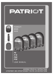
1
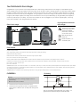
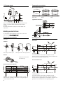
INTELLIGENT FENCING FOR THE COUNTRY
F L E X I B IL I T Y
DESIGN
VA L U E
P5
P10
P20
P30
USER MANUAL
W A R N I N G : R E A D A L L I N S T R UC T I O N S
`çåíÉåíë=
Your Patriot electric fence charger ............................. 1
Installation............................................................. 1
Building an electric fence......................................... 2
Safe electric fence construction................................. 3
© Tru-Test Limited, 2004. All rights reserved.
Safety information................................................... 3
Definition of special terms........................................ 4
No part of this publication may be photocopied, reproduced, stored in a retrieval
system, or transmitted in any form or by any means, electronic, mechanical,
photocopying, recording or otherwise without the prior written permission of TruTest Limited. Product specifications may change without prior notice.
Requirements for electric animal fences ..................... 4
For more information about the Patriot range of quality products, see
www.patriotglobal.com.
Frequently asked questions/Troubleshooting ............... 5
Tru-Test Limited
25 Carbine Road
Mt Wellington
Auckland 1006
New Zealand
Servicing ............................................................... 5
Product specifications.............................................. 5
Patriot, P5, P10, P20 and P30 are trademarks of Tru-Test Corporation Limited.
Issue 2 3/05
Postal address:
P O Box 51078
Pakuranga
Auckland 1730
New Zealand
vçìê=m~íêáçí=ÉäÉÅíêáÅ=ÑÉåÅÉ=ÅÜ~êÖÉê=
Congratulations on your purchase of this quality Patriot electric fence charger. Patriot electric fence chargers are manufactured by the
world’s leading electric fencing company and are the product of over 65 years of electric fencing experience. An extremely versatile charger,
the Patriot is ideally suited to the control of all types of livestock from horses to prize cattle. The charger is highly effective for controlling
predators and can even be used for pet management. This “go-anywhere” electric fence charger is also perfect for intensive strip grazing.
Using the power adapter supplied, the charger can be connected to 110 V line input. Alternatively, by using the battery lead supplied, it
can also be powered by a 12 V battery. The electric fence charger can even be plugged into your vehicle’s cigarette lighter, for fencing
horses when travelling or trail riding (separate lead required).
=
bäÉÅíêáÅ=ÑÉåÅÉ=ÅÜ~êÖÉê=
hÉó=íç=ëóãÄçäë=çå=íÜÉ=ÉäÉÅíêáÅ=
ÑÉåÅÉ=ÅÜ~êÖÉê=
The electric fence charger
should only be opened or
repaired by qualified
personnel, to reduce the
risk of electric shock.
Read full instructions
before use.
Double insulation – no
serviceable parts.
mçïÉê=~Ç~éíÉê=
Important safety instructions!
When using electrical products, basic precautions should always be practised, including the following:
Read and follow all safety instructions.
Read and follow all instructions provided with the electric fence charger and power adapter.
Do not use an extension cord with the power adapter.
Refer to the National Electrical Code ANSI/NFPA70 for information about the installation of wiring and clearances from lighting and power conductors.
Installation work and electrical wiring must be done by qualified person(s) in accordance with all applicable codes and standards, including fire-rated construction.
Do not install or use within 10 feet of a pool.
Do not use in a bathroom.
WARNING! Risk of electric shock. When used outdoors or in a wet location, install only to a covered, Class A GFCI protected receptacle that is weatherproof with the power adapter
connected to the receptacle. If a corrected GFCI protected receptacle is not currently installed, contact a qualified electrician for proper installation. Ensure that nothing interferes
with completely closing the receptacle cover.
WARNING! Risk of fire. Installation involves special wiring methods to run wiring through a building structure. Consult a qualified electrician.
fåëí~ää~íáçå=
NO=s=Ä~ííÉêó=
Warning!
- Disconnect power before making changes to fence or
ground wiring
- Mount out of reach of children.
1
2
Connect the Fence output terminal to the fence.
Connect the Fence ground terminal to a separate ground
system that is at least 33’ (10 m) away from other ground
systems.
Only use the battery lead supplied with your charger, or a
genuine Patriot replacement (part number 804138).
1
NNM=s=éçïÉê=~Ç~éíÉê=
qÉãéçê~êó=ÑÉåÅÉ=ÅçåëíêìÅíáçå=
oÉÅçããÉåÇÉÇ=ïáêÉ=ëé~ÅáåÖ=
Dairy cattle
Sheep
Cattle
qóéáÅ~ä=ÑÉåÅÉ=ÅçåëíêìÅíáçå=
Only use the power adapter supplied with your electric fence
charger, or a genuine Patriot replacement (part number
804129).
See Safety information on page 3 for power adapter care
instructions.
_ìáäÇáåÖ=~å=ÉäÉÅíêáÅ=ÑÉåÅÉ=
For information about building an electric fence, refer to the
Patriot website www.patriotglobal.com.
mÉêã~åÉåí=ÑÉåÅÉ=ÅçåëíêìÅíáçå=
dêçìåÇáåÖ=~=ÑÉåÅÉ=
You need:
^ää=äáîÉ=ÑÉåÅÉ=
fåëìä~íçêë=
Steel rod post Steel T post
Wood post claw Wood post pinlock
píê~áåÉêë=
Tension to no more than
200 lb (90 kg)
For most soil types.
The animal receives a shock when it completes a circuit
between the fence and the ground system. The fence above has
all live wires and requires conductive soils.
dêçìåÇ=ïáêÉ=êÉíìêå=ÑÉåÅÉ=
oÉÅçããÉåÇÉÇ=ÑÉåÅÉ=ÅçåëíêìÅíáçå=
For dry, sandy or frozen ground conditions, where soil
conductivity is low.
H-Brace – Very simple to erect and most suitable as a high
tension strainer, excellent in areas where the soil gets very wet
or where heavy frost occurs.
2
The animal receives a shock when it completes a circuit
between a live wire and a ground wire. The fence above has
both live wires and ground wires (not insulated to the post). The
ground wire is connected back to the grounding system.
fåëí~ääáåÖ=~åÇ=íÉëíáåÖ=~=ÖêçìåÇ=ëóëíÉã=
p~ÑÉ=ÉäÉÅíêáÅ=ÑÉåÅÉ=ÅçåëíêìÅíáçå=
Select a suitable site for the ground system. Sites need to be:
At least 33’ (10 m) from other ground systems (e.g.
telephone, 110 V power or the ground system from another
electric fence charger).
•
Away from stock or other traffic that could interfere with the
installation.
•
At a site that can be easily observed for maintenance.
•
Ideally at a site that has damp soil (e.g. a shaded or
swampy location). Note that the ground does not need to be
directly adjacent to the electric fence charger installation.
Drive 6’6” (2 m) ground rods into the soil. Use high-voltage,
insulated cable and ground clamps to continuously connect the
ground rods and the charger’s Fence ground terminal. Make sure
the insulation is stripped back to ensure good contact between
the wire and the ground rod. The table below specifies the
minimum number of 6’6” (2 m) ground rods recommended for a
grounding system:
•
bäÉÅíêáÅ=ÑÉåÅÉ=ÅÜ~êÖÉê=
dêçìåÇ=êçÇë=
P5
1
P10
2
P20
3
P30
4
For an all live fence only, test the ground system using the
following procedure:
1
2
3
4
5
Turn off the electric fence charger.
At least 330’ (100 m) away from the electric fence charger,
short-circuit the fence by laying several steel rods or lengths
of pipe against the fence. For best results, the fence voltage
should be lowered to 2 kV or less. In dry or sandy
conditions, it may be necessary to drive the rods up to 12”
(300 mm) into the ground.
Note: It is not acceptable to short-circuit a ground wire
return system to the ground wire of the fence.
Turn the electric fence charger back on.
Using a digital voltmeter, ensure that the fence voltage is
below 2 kV.
Check your ground system. Insert the voltmeter’s ground
probe into the ground at the full extent of the lead, and hold
the other terminal against the last ground rod. The tester
should not read more than 0.3 kV. Anything higher than
this indicates that better grounding is required. Either add
more ground rods or find a better ground area to drive in the
ground rods.
Note: When grounding electric fence chargers located in
dairies, ground at least 65’ (20 m) away from the dairy
using double-insulated wire to avoid touching the dairy
building or equipment.
Warning! Read before use.
An electric fence can be hazardous when there is a risk of
entrapment or entanglement, or other hazards exist. Serious
injury or death may result. Take all steps to avoid the risk of
entrapment or entanglement. This safety information should be
read in conjunction with Requirements for electric animal
fences on page 4.
e~ò~êÇë=
! Do not climb through or under an electric fence. If it is
necessary to cross an electric fence use a gate or specially
designed crossing point.
! Do not allow young or infirm persons to use this electric fence
charger without supervision. Do not allow young children to play
with this charger or near an electric fence or electrified wires.
! Do not electrify barbed wire.
! Do not support off-set electrified wires less than 6” (150 mm)
from a barbed wire fence.
! Do not electrify any fence construction which could lead to
entanglement of persons or animals. We recommend for
instance, that no more than one electrified off-set wire be
supported on either side of a barbed wire or mesh fence.
! Do not supply an electric fence from two chargers.
! Do not allow electrified wires from two chargers on the same or
adjacent properties to be less than 6’6” (2 m) apart.
! Do not place charger ground electrodes less within 33’ (10 m)
of any part of a power supply ground system or
telecommunications ground system.
! Do not run electric fence wires above or close to overhead power
or communication lines.
aìíó=íç=íÜÉ=éìÄäáÅ=
Fasten warning signs to electric fence posts or wires at frequent
intervals along any public roads or pathways. Incorporate a nonelectrified gate or stile where an electric animal fence crosses a
public pathway and fasten warning signs to fence posts or wires
adjacent to the crossing.
For more information, contact Patriot or your local Patriot dealer.
Refer to www.patriotglobal.com for contact details.
p~ÑÉíó=áåÑçêã~íáçå=
Warning!
- Risk of electric shock.
- Do not connect simultaneously to a fence and to any other
device such as a cattle trainer or a poultry trainer.
Otherwise, lightning striking your fence will be conducted to
all other devices.
- Do not place or store power adapter where it can be
exposed to any potential wet location. Do not place in or
drop into water or other liquid. If the power adapter falls
into water, do not attempt to reuse it. Electric shock may
result.
3
fãéçêí~åí=ë~ÑÉíó=áåëíêìÅíáçåë=
be effected by means of electrically non-conductive material or
an isolated metal barrier.
When using electrical products, basic precautions should always
be practiced including the following:
1 READ AND FOLLOW ALL SAFETY INSTRUCTIONS.
2 Read and follow all instructions provided with the electric
fence charger and power adapter.
3 Do not use an extension cord with the power adapter.
4 Refer to the National Electrical Code ANSI/NFPA 70 for
information about the installation of wiring and clearances
from power and lighting conductors.
5 Installation work and electrical wiring must be done by
qualified person(s) in accordance with all applicable codes
and standards, including fire-rated construction.
6 Do not install or use within 10 feet of a pool.
7 Do not use in a bathroom.
8 WARNING: Risk of electric shock. When used outdoors or
in a wet location, install only to a covered Class A GFCI
protected receptacle that is weatherproof with the power
adapter connected to the receptacle. If a correct GFCI
protected receptacle is not currently installed, contact a
qualified electrician for proper installation. Ensure that
nothing interferes with completely
9 WARNING: Risk of fire. Installation involves special wiring
methods to run wiring through a building structure. Consult
a qualified electrician.
Barbed wire or razor wire shall not be electrified by an electric
fence charger.
aÉÑáåáíáçå=çÑ=ëéÉÅá~ä=íÉêãë=
Connecting leads and electric animal fence wires shall not cross
above overhead power or communication lines.
Electric fence charger/Charger – An appliance that is intended to
periodically deliver voltage impulses to a fence connected to it.
Crossings with overhead power lines shall be avoided wherever
possible. If such a crossing cannot be avoided it shall be made
underneath the power line and as nearly as possible at right
angles to it.
Fence – A barrier for animals or for the purpose of security,
comprising one or more conductors such as metal wires, rods or
rails.
Electric fence – A barrier that includes one or more electric
conductors, insulated from ground, to which electric pulses are
applied by an electric fence charger.
A non-electrified fence incorporating barbed wire or razor wire
may be used to support one or more offset electrified wires of an
electric animal fence. The supporting devices for the electrified
wires shall be constructed so as to ensure that these wires are
positioned at a minimum distance of 6” (150 mm) from the
vertical plane of the non-electrified wires. The barbed wire and
razor wire shall be grounded at regular intervals. Go to
www.patriotglobal.com for information regarding grounding.
A distance of at least 33’ (10 m) shall be maintained between
the electric fence charger ground electrode and any other
grounding system connected parts such as the power supply
system protective ground or the telecommunication system
ground.
Connecting leads that are run inside buildings shall be effectively
insulated from the grounded structural parts of the building. This
may be achieved by using insulated high voltage cable.
Connecting leads that are run underground shall be run in
conduit of insulating material or else insulated high voltage cable
shall be used. Care must be taken to avoid damage to the
connecting leads due to the effects of animal hooves or vehicle
wheels sinking into the ground.
Connecting leads shall not be installed in the same conduit as
mains supply wiring, communication cables or data cables.
If connecting leads and electric animal fence wires are installed
near an overhead power line, the clearances shall not be less
than those shown in the table below.
Minimum clearances from power lines for electric animal fences:
Ground electrode – Metal structure that is driven into the ground
near an electric fence charger and connected electrically to the
output Fence ground terminal of the electric fence charger, and
that is independent of other grounding arrangements.
mçïÉê=äáåÉ=îçäí~ÖÉ=
aáëí~åÅÉ=
≤1000 V
10’ (3 m)
>1000 to ≤33,000 V
13’ (4 m)
Connecting lead – An electric conductor, used to connect the
electric fence charger to the electric fence or the ground
electrode.
>33,000 V
14’ (8 m)
oÉèìáêÉãÉåíë=Ñçê=ÉäÉÅíêáÅ=~åáã~ä=ÑÉåÅÉë=
Electric animal fences and their ancillary equipment shall be
installed, operated and maintained in a manner that minimizes
danger to persons, animals or their surroundings.
Electric animal fence constructions that are likely to lead to the
entanglement of animals or persons shall be avoided.
An electric animal fence shall not be supplied from two separate
electric fence chargers or from independent fence circuits of the
same electric fence charger.
For any two separate electric animal fences, each supplied from
a separate electric fence charger independently timed, the
distance between the wires of the two electric animal fences
shall be at least 6’6 (2 m). If this gap is to be closed, this shall
4
If connecting leads and electric animal fence wires are installed
near an overhead power line, their height above the ground shall
not exceed 10’ (3 m). This height applies to either side of the
orthogonal projection of the outermost conductors of the power
line on the ground surface, for a distance of:
6’6” (2 m) for power lines operating at a nominal voltage
not exceeding 1000 V.
•
50’ (15 m) for power lines operating at a nominal voltage
exceeding 1000 V.
Electric animal fences intended for deterring birds, household pet
containment or training animals such as cows need only be
supplied from low output electric fence chargers to obtain
satisfactory and safe performance.
•
In electric animal fences intended for deterring birds from
roosting on buildings, no electric fence wire shall be connected
to the electric fence charger ground electrode.
A warning sign shall be fitted to every point where persons may
gain ready access to the conductors.
by directing you straight to the fault. Go to
www.patriotglobal.com for more details.
Where an electric animal fence crosses a public pathway, a nonelectrified gate shall be incorporated in the electric animal fence
at that point or a crossing by means of stiles shall be provided.
At any such crossing, the adjacent electrified wires shall carry
warning signs.
Another tool used to locate faults is a digital voltmeter. When
using a digital voltmeter, simply isolate sections of your fence by
opening cut-out switches or otherwise disconnecting sections of
the fence from the main lead out wire/s. Measure the voltage
and determine whether the voltage has improved. If after
disconnecting a section of the fence you record a significant
improvement in fence voltage, it is likely that the fault is located
in the section of fence that you have just isolated. Often a visual
inspection of the faulty section will reveal the problem.
Any part of an electric animal fence that is installed along a
public road or pathway shall be identified at frequent intervals by
warning signs securely fastened to the fence posts or firmly
clamped to the fence wires.
•
The size of the warning sign shall be at least 4x8” (100x200 mm).
•
The background colour of both sides of the
warning sign shall be yellow. The inscription on
the sign shall be black and shall be either:
or the substance of “CAUTION: Electric Fence”.
•
The inscription shall be indelible, inscribed on both sides of the
warning sign and have a height of at least 1” (25 mm).
Ensure that all mains-operated, ancillary equipment connected
to the electric animal fence circuit provides a degree of isolation
between the fence circuit and the supply mains equivalent to
that provided by the electric fence charger.
Protection from the weather shall be provided for the ancillary
equipment unless this equipment is certified by the
manufacturer as being suitable for use outdoors, and is of a type
with a minimum degree of protection IPX4.
By carrying your voltmeter or fault finder when you move around
the farm you can regularly test your fence system and fix faults
before they lead to or result in a larger problem.
qÜÉêÉ=~êÉ=åç=äáÖÜíë=Ñä~ëÜáåÖ=çå=íÜÉ=ÉäÉÅíêáÅ=ÑÉåÅÉ=ÅÜ~êÖÉê=
Check the power supply. If fence charger is connected to line
power adapter, ensure that the power is switched on.
Disconnect the power then reconnect the power 30 seconds
later.
If fence charger is connected to a 12 V battery, ensure that the
positive (red) clip is connected to the positive terminal on the
battery and the negative (black) clip is connected to the negative
terminal on the battery.
If the fence charger’s pulse light still does not flash, disconnect
the battery then reconnect the battery 30 seconds later. Also,
check the battery voltage.
If the fence charger still does not operate, refer to your warranty
conditions.
cêÉèìÉåíäó=~ëâÉÇ=
èìÉëíáçåëLqêçìÄäÉëÜççíáåÖ=
eçï=Çç=f=áåÅêÉ~ëÉ=ÑÉåÅÉ=îçäí~ÖÉ\=
Sometimes recent extensions to your fence, a poor fence layout,
or soil conditions may be causing inadequate voltage.
To check the electric fence charger, disconnect it from the fence
and the ground system. Measure the voltage across the electric
fence charger terminals with a digital voltmeter. If the voltage is
less than 6 kV your electric fence charger may be faulty. Go to
www.patriotglobal.com for more details.
eçï=Çç=f=äçÅ~íÉ=Ñ~ìäíë\=
The most common cause of low voltage is faults on the fence
line. Faults can be arcing faults that often make a clicking sound
that can be heard when walking along a fence line. These are
most often caused by faulty insulators or poor connections (loose
clamps, tied wires or faulty cutout switches) and are normally
fixed by replacing the faulty insulator or repairing the faulty
connections. Note: Always use specially made joining clamps or
crimps to secure wire to wire connections on the fence line.
Another fault type is a short circuit fault. This fault occurs when
a live fence wire becomes connected in some way to the ground.
A short circuit fault wastes the power of the electric fence
charger by drawing energy away from where it is needed, the
fence line. A common cause of short circuit faults is vegetation
touching the live wires. Regular clearing of vegetation from the
fence line will enhance your electric fence charger’s
performance. The best method to locate a short circuit fault is to
use a special fault finder. These products save considerable time
pÉêîáÅáåÖ=
This product cannot be serviced. Please refer to your warranty
conditions.
pÉêîáÅÉ=çÑ=ÇçìÄäÉ=áåëìä~íÉÇ=~ééäá~åÅÉë=
In a double insulated electric fence charger, two systems of
insulation are provided instead of grounding. Patriot chargers
contain no serviceable parts.
mêçÇìÅí=ëéÉÅáÑáÅ~íáçåë=
mR=
mNM=
mOM=
mPM=
Input
voltage
12 V,
45 mA
12 V,
90 mA
12 V,
170 mA
12 V,
300 mA
Peak
output
energy
up to 0.5 J
up to 1 J
up to 2 J
up to 3 J
Stored
energy
up to 0.7 J
up to 1.3 J
up to 2.7 J
up to 4.6 J
Output
voltage
8.0 kV max,
4.5 kV at
500 Ω
9.7 kV max, 10.5 kV max, 10.5 kV max,
5.4 kV at
6.0 kV at
6.0 kV at
500 Ω
500 Ω
500 Ω
Table represents typical values
5
INTELLIGENT FENCING FOR THE COUNTRY
S AV E T H E S E I N S T R UC T I O N S
w w w . p a t r i ot g l o b a l . c o m