1
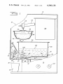
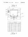
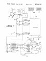
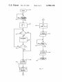
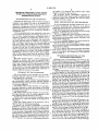
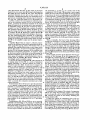
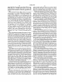
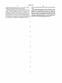
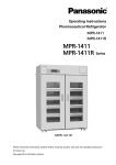
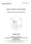
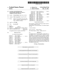
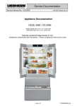
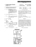
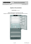
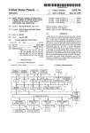
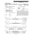
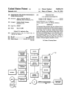
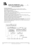
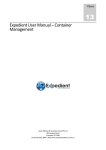
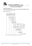
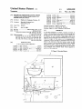
Unlted States Patent 119]
[11]
4,360,128
Neumann
[45]
Nov. 23, 1982
[54]
[75]
BEVERAGE DISPENSER HAVING TIMED
3,126,812
3/1964 Nau ................................. .. 222/66 X
OPERATING PERIOD RESPONSIVE To
3,235,922
2/ 1966
Kaji . . . . . . . . . . .
. . . .. 222/70 X
RESERVOIR QUANTITY
3,481,509 12/1969
Marhauer .
.. 222/58 X
3,665,156
Lee ............................. .. 219/333
Inventor:
Charles G. Neumann, Palatine, 111.
3,906,475 9/1975 Rubin et al
_
[73]
4,149,412
Asslgneer
Schaumburg, 111.
4,265,371
Desai et a1. ......................... .. 222/70
Assistant Examiner—Edward M. Wacyra
Jul‘ 29’ 1980
Attorney, Agent, or Firm—Shenier & O’Connor
Int. Cl.3 ..................... .. A47J 31/46; G04C 23/38
[52]
us. c1. ...................................... .. 222/26; 99/281;
219/333; 219/433; 219/518; 222/64; 222/641;
222/146 HE; 340/613
[56]
340/612 X
.. 219/518 x
Primary Examiner~Robert B. Reeves
[51]
[58]
5/1981
.......... ., 222/23 X
Fish ..................... ..
4,164,644 8/1979 Remsnyder et al
_
[22] Flled'
4/1979
Reynolds Products Inc"
[21] App]. No.: 173,271
.
5/1972
[57]
ABSTRACT
A beverage dispenser in which a sensor provides an
output corresponding to the level of the beverage in a
Field of Search ..................... .. 222/23, 25, 5s, 26,
222/64, 65, 66, 70, 146 HE; 99/230, 281, 235,
storage reservoir from which the beverage is dispensed
In response to user actuation a dispensing valve is en
233; 219/214, 322, 333, 433, 513; “11/473,479,
567, 568, 569; 414/21; 340/612, 613, 614, 6.13,
620, 623, 624, 625
References Cited
abled for such a time interval, determined in accordance
with the output of the sensor, as to compensate for
variations in flow rate due to variations in the beverage
U.S. PATENT DOCUMENTS
1,719,498
1,769,639
7/1929
7/1930
2,836,672
5/1958 Craven, Jr. et al.
level in the reservoir. The level sensor output is also
used to control a level-indicating display and to disable
the reservoir heater when the reservoir is empty. Pref
Bernard ............................... .. 99/281
Gustafson ......... .,
340/613
. 340/613 X
2,855,476 10/1958
Garrard ...................... .. 222/70 X
2,935,010 5/1960
Arnett et a1. ................... .. 222/70 X
erably the sensor is a strain gauge adhered to the surface
of a relatively thin resilient beam which supports a
portion of the reservoir.
9 Claims, 5 Drawing Figures
/2
U.S. Patent
Nov. 23, 1982
\
f”M
42
20
Sheet 1 of4 __
4,360,128
U.S. Patent
Nov. 23, 1982
Sheet 2 0f 4
I-LLS E
/2
| BREW
DOWN
2 BREwS
ooum
5 BREWS
I20
DIG PENSE
32
I
T/Mf (I)
5- 02.
6 oz.
/0_ a2.‘
1
2.8
3.3
5.6
2
2-8
3.5
5.6
5'
2.9
3-4
5-8
4
3.1
3.65
6.2
5
5'3
5.9
6.6
6
5.6
4.3
7.2
7
3-9
4.65
7.9
g
4.5
5.1
8-6
4,360,128
U.S. Patent
Nov. 23, 1982
Sheet 4 of 4
4,360,128
130
4
SET
l 2’\ TIMER AT 0
V
ENABLE
132
144
SOLENOID
INCREMENT
I
146
DISABLE
SOLENOID
7
7
INPUT
14-0
RETURN TO
START
138
150
DESIRED
QUANTITY
V
TIME =
TIME (I) FOR
DESIRED
QUANTITY
FIG. 4
14-8
4,360,128
1
2
the surface of a relatively thin resilient beam which
supports a portion of the reservoir.
BEVERAGE DISPENSER HAVING TIMED
OPERATING PERIOD RESPONSIVE TO I
My invention further contemplates apparatus in
RESERVOIR QUANTITY
which the level sensor output is used to control a level
indicating display and to disable the reservoir heater
BACKGROUND OF
INVENTION
when the reservoir is empty.
Apparatus for dispensing coffee or other beverage in
BRIEF DESCRIPTION OF THE DRAWINGS
In the accompanying drawings which form part of
response to the deposit of a coin or the actuation of a
switch are well known in the art. In one type of such
apparatus, a storage pan or reservoir is used to hold the
the instant speci?cation and which are to be read in
conjunction therewith and in which like reference nu
previously prepared beverage prior to dispensing and to
dispense the beverage from the storage pan through a
merals indicate like parts in the various views:
FIG. 1 is a fragmentary side elevation of my beverage
dispenser, with parts shown in section.
Various expedients have been employed in the prior
FIG. 2 is a fragmentary front elevation of the bever
art to control the amount of beverage delivered to a 15
age dispenser shown in FIG. 1, illustrating the front
user. In some vending machines, the dispense valve is
display panel and strain-gauge sensor associated with
opened by actuation of a push-button switch that be
controllable valve.
the beverage storage pan.
comes operable if a coin is deposited. The valve does
not close until the button is released. If a customer is
FIG. 3 is a schematic diagram of a control circuit for
able to position a second cup with one hand after the 20 the beverage dispenser shown in FIG. 1.
FIG. 4 is a flow chart illustrating a program which
?rst cup is ?lled while keeping the button depressed
may be followed by the microcomputer of the control
with the other hand, he can obtain two or more cups for
the price of only one. In other systems, the dispense
valve is-energized for a ?xed time interval to dispense
the desired amount of beverage; This method is highly
unsatisfactory, however, since the flow rate is depen
dent on the pressure head from the reservoir, which
varies directly with the level of beverage in the reser
voir.
circuit shown in FIG. 4.
FIG. 5 is a table of the various time bases associated
25 with various desired amounts of beverage and sensed
levels of beverage in the storage pan of the dispenser
shown in FIG. 1.
DETAILED DESCRIPTION OF THE
PREFERRED EMBODIMENT
Referring
now to the drawings, my beverage dis
technique in which a ?rst valve is actuated to ?ll a
penser,
indicated
generally by the reference numeral 10,
chamber with beverage from the reservoir and a second
is enclosed by a housing 12 having a front display panel
valve then actuated to ?ll the cup from the chamber.
While these systems insure the dispensing of a con 35 14 and a side control panel 16. The housing 12 is formed
with a recess 18 at the lower end of the front panel in
trolled amount of beverage irrespective of the level in
which a cup 20 may be placed to receive a dispensed
the reservoir, they do not permit ready adjustment to
beverage.
dispense different amounts of beverage.
A storage pan 22 holds a supply of a beverage 28 such
as coffee supplied to the pan through an aperture 26
SUMMARY OF THE INVENTION
formed in a top cover 24. Storage pan 22 rests on a
One of the objects of my invention is to provide a
transversely extending ridge 36 formed in a support 30
beverage dispenser which accurately dispenses a con
near the rear end thereof. Side ?anges 32 and a rear
Still other systems employ a positive displacement
30
trolled amount of a beverage.
Another object of my invention is to provide a bever
age merchandiser which prevents multiple dispensa
tions of a beverage when the cost of only a single deliv
ery has been deposited.
Yet another object of my invention is to provide a
beverage dispenser in which the amount of beverage
dispensed does not depend on the level of the beverage
?ange 34 on the support 30 con?ne the storage pan 22
laterally and rearwardly without bearing any of the
45
weight of the pan 22. The front end of the storage pan
22 rests on the inverted-V-shaped front end of a resilient
metal strip or arm 38 secured at the rear end thereof to
a portion of the housing 12 and extending through an
aperture 40 formed in the support 30. A strain gauge 42
secured to the lower surface of the resilient arm 38 with
its gauge axis running fore and aft relative to the dis
penser 10 senses the compressional, or negative, strain
beverage dispenser which is readily adjustable to dis
in the lower surface of the arm 38 resulting from the
pense different desired amounts of beverage.
weight of the storage pan 22 and the beverage 28 con
Another object of my invention is to provide a bever 55 tained therein.
age dispenser in which the number of moving parts is
The cup 20 receives the beverage 28 through a dis
minimized.
pensing valve 44 located at the lower front end of the
Other and further objects of my invention will be
storage pan 22. Actuation of a solenoid 50 causes lever
apparent from the following description. _
arm 52 to rotate about its pivot 54, pressing the actuator
In general, my invention contemplates a beverage
button 48 of the valve 44 inwardly to allow the bever
dispenser in which a sensor provides an output corre
age 28 to ?ow through the spout 46 and into cup 20.
sponding to the level of the beverage in a storage reser
The beverage 28 may be coffee which is supplied to
voir from which the beverage is dispensed. In response
the storage pan 22 from a brew basket 56 disposed
to user actuation a dispensing valve is enabled for such
above the aperture 26 in the top cover 24. As is known
a time interval, determined in accordance with the out 65 in the art, brew basket 56 receives a replaceable ?lter
put of the sensor, as to compensate for variations in flow
cup_5v8 partially ?lled with ground coffeev 60 and re
rate due to variations in the beverage level in the reser
ceives hot water from a spray discharge head 62 dis
voir. Preferably, the sensor is a strain gauge adhered to
posed at the ,top of the brew basket. A spray discharge
in a storage reservoir.
Still another object of my invention is to provide a
3
4,360,128
valve 64 controls the ?ow of hot water to the brew
basket from a hot water tank 68 through a discharge line
66. While the brew basket 56, hot water tank 68 and
associated elements do not per se form a part of my
invention, a detailed description of an automatic bever
4
the potentials v3, v9 and v10. As a result, each of the
comparators C8, C9 and C10 provides a zero output.
When the level of the beverage 28 in the storage pan 22
drops below the level corresponding to two-thirds full,
v3 then exceeds vs, resulting in a high output from com
parator C8. An AND circuit 94 responsive to the output
of comparator C8 then provides a high output to ener
age brewer containing these elements may be found in
US. Pat. No. 3,443,508, issued to D. S. Reynolds et al.
In FIG. 3, I show the control circuit, indicated gener
gize an indicator light 98 on the front panel of the dis
ally by the reference numeral 70, for my beverage dis
penser 10 indicating that the level of the beverage 28 is
penser. I connect the electrical terminals of the strain 10 10 cups, or one brew, down from its initial level.
gauge 42 respectively to ground and to one terminal of
When the level of the beverage 28 drops below one
an adjustable resistor 76, the other terminal of which I
third full, or 10 cups, v9 also exceeds vs, resulting in a 1
connect to a line 72 leading from a source of positive
or high output from comparator C9 as well as from C8.
DC potential. Gauge 42 and resistor 76 make up two
The high output of comparator C9 is applied to an
legs of a bridge, the other two legs of which are formed
inverting input of AND circuit 94 to disable the “one
by resistors 74 and 78. Respective resistors 82 and 86
brew down” indicator lamp 98. At the same time, the
connect the output terminals of the bridge to the invert
output of comparator C9 is fed to another AND circuit
ing and noninverting input terminals of a high-gain
96, the output of which energizes a “two brews down”
operational ampli?er 80. Respective resistors 84 and 88
indicator lamp 100 on the front panel 14 below indicator
couple the inverting and noninverting inputs of ampli
lamp 98.
When, eventually, the level of the beverage 28 in
?er 80 to the ampli?er output and to ground respec
tively.
storage pan 22 drops to a near empty level, all three
potentials v8, v9 and v10 exceed the strain gauge poten
tial vs. As a result, all three comparators C8, C9 and C10
Ampli?er 80 provides an output v, which is propor
tional to the difference between the potentials across the
strain gauge 42 and the resistor 74. Resistor 76 is so 25 provide zero or low outputs. The zero output of com
adjusted that ampli?er 80 provides a zero output when
the pan 22 is empty. As more beverage 28 is supplied to
the pan 22, the increased pressure on the resilient strip
parator C10 feeds inverting inputs of AND circuits 94
and 96 to disable respective indicator lights 98 and 100
and, in addition, energizes a “three brews down” indica
tor lamp 102 disposed on the front panel 14 below lamps
38 causes an increased compressive, or negative, strain
on the lower surface of the strip, in turn decreasing the 30 98 and 100.
electrical resistance of the strain gauge 42. As a result,
In the normal operation of the dispenser 10, the tem
strain gauge 42 supplies a reduced potential to the in
perature of the beverage 28 in the storage pan 22 is
verting input of ampli?er 80, thereby resulting in an
controlled by a resistive heating coil 108 disposed in the
pan 22 by a thermistor 116 also disposed in the pan 22.
Thermistor 116 is coupled in a bridge circuit between
ground and one terminal of an adjustable resistor 112,
the other terminal of which is coupled to DC voltage
line 72. Resistors 114 and 118 form the other legs of the
increasingly positive ampli?er output.
I convert the output of ampli?er 80, which appears as
an analog signal on line 90, to a series of quantized
signals indicating in a discrete fashion the extent to
which the pan 22 is ?lled. To this end, I compare the
signal V, with a plurality of reference potentials v1 to
bridge. The bridge output terminals are coupled respec
v10 derived from respective potentiometers R1 to R10 40 tively to the inverting and to the noninverting inputs of
coupled between the DC voltage line 72 and ground.
a differential ampli?er 110. I couple the heating element
Respective comparators C1 to C10 each receive one
108 between the output of ampli?er 110 and one termi
input from line 90 and the other input as one of the
nal of a normally closed relay-controlled switch S, the
comparison potentials v1 to v10. Comparators C1 to C7
other terminal of which I couple to line 72.
each provide a 1, or high, output whenever the poten 45
In the normal operation of the heating control circuit,
tial v, on line 90 exceeds the comparison potential but
any increase in the temperature of the beverage 28 will
provide a zero, or low, output otherwise. Comparators
result in a corresponding decrease in the resistance of
C8 to C10 on the other hand each provide a low output
thermistor 116, thereby resulting in a lower potential
when v, exceeds the comparison potential and a high
being applied to the inverting input of ampli?er 110. As
output otherwise.
Potentiometers R1 to R7 are set to provide potentials
v1 to v7 spaced in approximately equal steps between a
50
a result, the output of ampli?er 110 rises, causing the
potential applied to the heating coil 108 to drop, thereby
leading eventually to a suitably lower temperature of
potential v1 corresponding to a nearly full storage pan
the beverage 28. Variable resistor 112 is set at a suitable
and a potential v7 corresponding to a nearly empty
level to establish a proper temperature of the beverage
storage pan. Thus, when storage pan 22 is ?lled to its 55 28 in the pan 22.
capacity of approximately 30 cups, none of the outputs
In response to the change of the output of comparator
of the comparators C1 through C7 are low. On the
C10 to zero when the beverage reaches a near empty
other hand, when the storage pan 22 is nearly empty, all
level in the pan 22, a driver circuit 104 energizes a relay
of the comparator outputs are low. Intermediate levels
106, opening the switch S and thereby disabling the
of beverage 28 in the storage pan 22 result in an interme 60 heating element 108.
diate number of the comparators C1 to C7 providing
I couple the outputs of comparators C1 to C7 to a
low outputs.
microcomputer 92 such as an Intel 8048, sold by the
Potentiometers R8, R9 and R10 are set to provide
Intel Corporation of Santa Clara, Calif, and described
potentials corresponding to the output of ampli?er 80 I
in the Intel user’s manual entitled “MCS-48 Family of
when the storage pan 22 is two-thirds full, one-third full
Single Chip Microcomputers” (l978). FIG. 4 is a flow
and nearly empty, respectively. Thus, when the storage
chart illustrating a program which may be followed by
pan 22 is two-thirds full or more, that is, containing 20
the computer 92 in generating suitable time bases for
or more cups of coffee, the potential vs exceeds each of
controlling the dispensing of beverage 28 from the stor
4,360,128
5
6
age pan 22. After the program starts (block 126),'it waits
madein details 'within the scope of my claims without
(block 128) for a normally open dispense button‘ 120,
coupled between a normally high input to computer. 92
and ground and mounted on the front-panel 14, 'toibe
departing from the spirit of my invention. It is, there
closed.
.
‘ ‘
fore, to be understood that my invention is not to be
limited to the speci?c details shown and described.
'1
' Having thus described my invention, what I claim is:
After the dispense button 120 is pushed, the program
1. Beverage dispensing apparatus including in combi
sets an index I at 1 (block 130) and interrogates the
nation a reservoir adapted to receive a beverage to be
corresponding comparator to determine whether the
output of that comparator is one, indicating that the
dispensed, means for sensing the amount of said bever
age in said reservoir, means responsive to user actuation
storage pan 22 is ?lled at least to they level set by the
corresponding one of potentiometers R1 to R7 (block
132). If the comparator output is l, the program leaves
the loop. Otherwise, the program increments the index
means responsive to said sensing means for controlling
the period of enablement of said dispensing means.
I by 1 (block 134) and asks (block 136) whether the
nation a reservoir adapted to receive a beverage to be
for dispensing said beverage from said reservoir, and
2. Beverage dispensing apparatus including in combi
index has now reached the number 8, indicating that 15 dispensed, means for sensing the amount of said bever
there are no more comparators to be checked. If the
age in said reservoir, means responsive to user actuation
index I is still 7 or less, the program returns to block 132
for
dispensing said beverage from said reservoir, means
to interrogate the next comparator to determine
responsive
to said sensing means for controlling the
whether its output is l. The program continues along
period
of
enablement
of said dispensing means, means
the loop comprising blocks 132 to 136 until either a 20
for heating the beverage contained in said reservoir, and
comparator with a 1 output is found or the index I
means responsive to said sensing means for disabling
said heating means.
reaches 8. Thus, when the program leaves the loop the
index I will be set at a number between 1 and 8 corre
3. Beverage dispensing apparatus including in combi
sponding to the “zone” to which the storage pan 22 is
nation
a reservoir adapted to receive a beverage to be
?lled.
25
dispensed, means for sensing the amount of said bever
Next, the program interrogates the outputs of a three
age in said reservoir, means responsive to user actuation
position selector switch 122 which may be set to select
for dispensing said beverage from said reservoir, means
a small (5 02.), medium (6 02.) or large (10 oz.) quantity
responsive to said sensing means for controlling the
of beverage to be dispensed. Switch 122, which may be
mounted on the side panel 16, grounds a normally high 30 period of enablement of said dispensing means, and
means responsive to said sensing means for displaying
?rst input to computer 92 if moved to the “small” posi
the amount of said beverage in said reservoir.
tion and grounds a second normally high input to com
4. Beverage dispensing apparatus including in combi
puter 92 if moved to the “large” position. Otherwise,
nation a reservoir adapted to be ?lled to one of a plural
both outputs remain high. After determining the desired
quantity of beverage to be dispensed, the program se 35 ity of ranges of levels with a beverage to be dispensed,
lects a suitable time base (block 140) from an internally
stored array of time bases shown in tabular form in FIG.
5. As is apparent from the table, the time base selected
depends both on the value of I, indicating the present
level of the tank 22, and the amount of beverage to be 40
dispensed.
means for supplying a predetermined amount of bever
age to said reservoir, said ranges corresponding in ex
tent to said predetermined amount, means for sensing
the particular one of said ranges to which said reservoir
is ?lled, and means responsive to said sensing means for
displaying said sensed range.
5. Beverage dispensing apparatus including in combi
The program next sets a timer (not shown) internal to
nation a reservoir adapted to receive a beverage to be
computer 92 to zero to mark the beginning of the dis
dispensed, sensing means for providing an output corre
pense sequence, and thereafter provides a suitable signal
to a solenoid driver 124 to energize the dispense sole 45 sponding to the level of said beverage in said reservoir,
means for dispensing said beverage from said reservoir,
noid 50 (block 144). Energization of solenoid 50 causes
the beverage 28 to be dispensed through the spout 46 in
means for preselecting a desired amount of beverage to
be dispensed, and means responsive to user actuation for
the manner described ‘above. When the elapsed time as
measured by the timer output equals the previously
selected time base (block 146), the program disables
50
(block 148) the solenoid 50, thereby terminating the
enabling said dispensing means for a time interval deter
mined in accordance with said preselected desired
amount and the output of said sensing means.
6. Beverage dispensing apparatus including in combi
dispensing sequence. Thereafter, the program returns
nation a reservoir adapted to receive a beverage to be
(block 150) to the starting block 126 to await the subse
dispensed, a resilient beam positioned to support a por
quent actuation of the dispense button 120.
It will be seen that I have accomplished the objects of 55 tion of said reservoir at one end of said beam, a strain
my invention. My beverage dispenser dispenses a con
gauge adhered to a surface of said beam, means for
trolled amount of a beverage and is readily adjustable to
dispensing said beverage from said reservoir, and means
dispense different desired amounts of beverage. Fur
responsive to user actuation for enabling said dispensing
ther, the amount of the beverage dispensed does not
means for a time interval determined in accordance
depend on the level of the beverage in the storage reser
with the output of said strain gauge.
voir. Finally, my beverage dispenser resists unautho
rized attempts to obtain multiple dispensations of a bev
erage.
It will be understood that certain features and sub
combinations are of utility and may be employed with 65
out reference to other features and subcombinations.
This is contemplated by and is within the scope of my
claims. It is further obvious that various changes may be
7. Beverage dispensing apparatus including in combi
nation a reservoir adapted to receive a beverage to be
dispensed, a resilient beam positioned to support a por
tion of said reservoir at one end of said beam, said beam
being relatively thin in the direction of bending under
the weight of said reservoir, means for sensing strain in
said beam, means for dispensing said beverage from said
reservoir, and means responsive to user actuation for
7
4,360,128
8
time interval determined in accordance with said sensed
strain.
enabling said dispensing means for a time interval deter
mined in accordance with said sensed strain.
9. Beverage dispensing apparatus including in combi
8. Beverage dispensing apparatus including in combi
nation a reservoir adapted to receive a beverage to be
nation a reservoir adapted to receive a beverage to be 5 dispensed, a resilient member positioned to support a
portion of said reservoir, means for sensing strain in said
dispensed, a resilient beam positioned to support a por'
member, means for dispensing said beverage from said
tion of said reservoir at one end of said beam, means for
reservoir, and means responsive to user actuation for
sensing strain in said beam, means for dispensing said
enabling said dispensing means for a time interval deter
beverage from said reservoir, and means responsive to
mined in accordance with said sensed strain.
*
*
*
1k
I!‘
user actuation for enabling said dispensing means for a
15
25
30
35
45
55
60
65