1
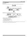
System Scale Printer
AC-4000D
SERVICE MANUAL
IMPORTANT
• Do not carry out installation, operation, service, or
maintenance until thoroughly understanding the
contents of this manual.
• Keep this manual available at all times for installation,
operation, service, and maintenance.
Manual No. 085-7322-04
PN 80817
To Provide Service Safely
In order to properly conduct maintenance and prevent the occurrence of accidents, be sure to perform
the operations below.
•Turn OFF the power switch, and unplug the power cord from the outlet.
•Keep the area around the machine clean.
Particularly with disassembly, if the power is switched ON when an object such as a detached screw is
left inside the main unit, serious damage may occur.
•Do not pull directly on the cords of the internal wiring. Doing so may result in broken wires or poor
connections. Always grasp the connector when plugging/unplugging a cord.
Pay particular attention to the thermal head cable.
•The thermal head and print head can be easily scratched, so be careful when cleaning them.
•Cautions are explained for each point of assembly and adjustment. To ensure proper operation, read
this manual thoroughly so that you fully understand it.
You can help improve this manual by calling attention to errors and by recommending improvements.
Please convey your comments to the nearest Ishida Company regional representative. Thank you!
Copyright © 2006 by Ishida Co., Ltd. All Rights Reserved.
No part of this manual may be reproduced in any form, by mimeograph or any other means, without
written permission of the publisher.
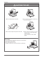
Precautions
SERVICE SAFETY
For correct maintenance, and to prevent accidents, please adhere to the following items during service.
• Ensure that the power switch is OFF before any maintenance work and remove the power cable
from the main power outlet.
• Keep the machine surroundings clean and tidy. Take additional care, especially during disassembly,
not to leave screws etc. inside the machine as this may lead to serious injury.
• Do not pull internal wiring cables as cable breaks, poor contact, etc. may take place. Always hold
the connector end before removing. Take special care with thermal head cable, where poor contact
may lead to damage.
• Take care when cleaning thermal heads and print heads, as these are easily damaged.
• There are precautions relating to assembly and adjustment parts. Read and understand the manual
thoroughly before attempting maintenance.
SAFETY CONSIDERATIONS
For safe operation, the following safety considerations must be observed.
Grounding
This machine requires protective grounding for safe operation. To avoid potential shock hazards, a
protective grounding conductor for the machine must be securely connected to the main grounding
provision by qualified service personnel.
Do not remove covers or enclosures
To avoid personal injury and shock, do not open or remove any covers or enclosures of the machine
unless specified in the manual.
Do not perform unspecified maintenance
For your personal safety, do not perform any maintenance procedures which are not specified in the
manual.
Disconnect power supply before servicing
To ensure your personal safety, disconnect the power supply before servicing.
i
AC-4000D Service Manual
No.085-7322-04
Precautions
X Do not disassemble the machine.
X Do not allow any liquids to come into contact with the machine.
X Do not drop or apply a strong shock to the scale.
X When cleaning the machine, only use a
soft dry cloth or a cloth wetted with a
neutral cleanser.
Never use thinner or other volatile
liquids.
Power Supply
• Use the appropirate voltage after referring to the specification
plate located on the machine.
• Use a dedicated power source.
(Voltage fluctuation may cause the machine to malfunction)
AC-4000D Service Manual
No. 085-7322-04
ii
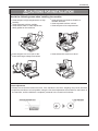
Precautions
Avoid the following areas when installing the machine
z
z
z
z
z
Areas subject to high temperatures or high
humidity
Areas exposed to direct sunlight
Areas where water or other liquids are
easily spilled on the machine
z
z
Areas subject to excissive vibration or
unstable surfaces
Areas exposed to direct cold air
Areas subject to low temperatures
Areas subject to a lot of dust or dirt
Areas with large voltage fluctuations
z
Areas where the scale is not level
z
Level adjustment
z
z
Always ensure that the machine is level. If the machine is not level, weighing may not be accurate.
Adjust the machine to a level position using the four level adjustment feet located on the buttom of
the machine, until the bubble is completely centered in the round level indicator.
iii
AC-4000D Service Manual
No.085-7322-04
Contents
Contents
CHAPTER 1 OVERVIEW
1.1
1.2
1.3
1.4
1.5
1.6
Appearance and Name of Each Part ................................................................................... 1-1
Display ................................................................................................................................. 1-1
Key Sheet ............................................................................................................................ 1-2
Printer ................................................................................................................................. 1-2
Main Specifications .............................................................................................................. 1-3
Layout of components .......................................................................................................... 1-4
CHAPTER 2 INSTALLATION
2.1
2.2
2.3
2.4
2.5
2.6
2.7
2.8
2.9
2.10
Packed Goods ..................................................................................................................... 2-1
Installation Environment ....................................................................................................... 2-2
Installing the stand ............................................................................................................... 2-2
Connecting the cable ........................................................................................................... 2-3
Label Loading ...................................................................................................................... 2-3
Power Cable Connection ..................................................................................................... 2-5
Power Switch “ON” .............................................................................................................. 2-5
Customer’s Specification Setup (Initialization, Setup, and Registration) ............................. 2-6
Normal Mode Display ........................................................................................................... 2-7
Label Batch Print Mode ...................................................................................................... 2-8
2.10.1 Basic operation ........................................................................................................ 2-8
2.10.2 Additional functions .................................................................................................. 2-9
2.10.3 Label batch printing on continuous paper ................................................................ 2-9
2.11 Scroll Message Display .................................................................................................... 2-10
2.12 Campaign Function ........................................................................................................... 2-10
CHAPTER 3 TEST MODE
3.1
3.2
3.3
Test Mode Menu List ............................................................................................................ 3-1
Test Mode Start .................................................................................................................... 3-2
Hardware Test ...................................................................................................................... 3-2
A/D check .......................................................................................................................... 3-2
KEY CHECK ...................................................................................................................... 3-4
DISPLAY CHECK .............................................................................................................. 3-4
RS232C CHECK ............................................................................................................... 3-5
APPLICATION PROGRAM No. ........................................................................................ 3-5
BIOS PROGRAM No. ....................................................................................................... 3-6
3.4 RAM Clear ........................................................................................................................... 3-7
SRAM CLEAR ................................................................................................................... 3-7
SETUP CLEAR ................................................................................................................. 3-8
TEST DATA SET ............................................................................................................... 3-8
APPLICATION COPY ....................................................................................................... 3-9
BIOS COPY ...................................................................................................................... 3-9
BOOT COPY ................................................................................................................... 3-10
AC-4000D Service Manual
No. 085-7322-04
iv
Contents
3.5 Printer Head ....................................................................................................................... 3-11
PRINTER HEAD ............................................................................................................. 3-11
RESISTANCE.................................................................................................................. 3-11
PRINT USAGE IN km ..................................................................................................... 3-12
3.6 Label Sensor Check ........................................................................................................... 3-13
3.7 Total Memory ..................................................................................................................... 3-14
3.8 ROM Switch ....................................................................................................................... 3-15
3.9 Peel Sensor Check ............................................................................................................ 3-17
3.10 Machine Type Check ........................................................................................................ 3-18
CHAPTER 4 SETUP MODE
4.1 Setup Mode Menu ................................................................................................................ 4-1
4.2 Starting Procedure for Each Mode ....................................................................................... 4-2
4.3 Starting Procedure for Setup Mode ..................................................................................... 4-2
4.4 Label Format [Print conditions] ............................................................................................ 4-3
LABEL FORMAT No. ......................................................................................................... 4-3
LABEL LENGTH + GAP .................................................................................................... 4-3
LABEL WIDTH .................................................................................................................. 4-4
LABEL SENSOR DISTANCE ............................................................................................ 4-4
LABEL DIE-CUT, CONTINUOUS ...................................................................................... 4-4
STORE NAME, ADDRESS ............................................................................................... 4-4
FIELD TITLE PRINT ......................................................................................................... 4-5
PEEL SENSOR ................................................................................................................. 4-5
TEST ITEM No. ................................................................................................................. 4-5
THERMAL HEAD CHECK ................................................................................................. 4-5
SUBTOTAL LABEL FORMAT No. ..................................................................................... 4-6
STORE No. PRINT ........................................................................................................... 4-6
MACHINE No. PRINT ....................................................................................................... 4-6
LABEL FORMAT EDIT ...................................................................................................... 4-7
FORMAT No. + [PLU] ........................................................................................................ 4-7
UNIT ................................................................................................................................. 4-8
DEFAULT PLU .................................................................................................................. 4-8
UNIT DATA ........................................................................................................................ 4-9
NUMBER OF UNITS ......................................................................................................... 4-9
LABEL LENGTH ................................................................................................................ 4-9
4.5 POS Code .......................................................................................................................... 4-10
POS FLAG 8/3 ................................................................................................................ 4-10
10 DIGIT FLAG 8/13 ....................................................................................................... 4-10
POS TYPE ...................................................................................................................... 4-10
BAR TYPE....................................................................................................................... 4-11
ITF ............................................................................................................................... 4-12
MANUFACTURE CODE ................................................................................................. 4-12
4.6 Item Code .......................................................................................................................... 4-13
BARCODE POSITION .................................................................................................... 4-13
DEPARTMENT CODE .................................................................................................... 4-13
GROUP CODE ................................................................................................................ 4-13
v
AC-4000D Service Manual
No. 085-7322-04
Contents
4.7
Default Data ....................................................................................................................... 4-14
DATE PRINT FLAG ......................................................................................................... 4-14
USED BY ........................................................................................................................ 4-14
PACKING TIME FLAG .................................................................................................... 4-14
EXPIRY TIME FLAG ....................................................................................................... 4-15
BEST BEFORE FLAG ..................................................................................................... 4-15
BEST BEFORE DATE ..................................................................................................... 4-15
UNIT TYPE ...................................................................................................................... 4-15
4.8 Total Mode Select .............................................................................................................. 4-16
DAILY TOTAL .................................................................................................................. 4-16
WEEKLY TOTAL ............................................................................................................. 4-16
MONTHLY TOTAL ........................................................................................................... 4-16
4.9 Open Price ......................................................................................................................... 4-17
4.10 PLU Select ........................................................................................................................ 4-18
SALES MODE ................................................................................................................. 4-18
UNIT PRICE .................................................................................................................... 4-18
MD (Mark Down) FLAG ................................................................................................... 4-18
MD (Mark Down) PRICE ................................................................................................. 4-18
FIXED WEIGHT .............................................................................................................. 4-19
PCS (Quantity) ................................................................................................................ 4-19
TARE ............................................................................................................................... 4-19
DATE PRINT ................................................................................................................... 4-19
USED BY ........................................................................................................................ 4-19
BEST BEFORE DATE FLAG .......................................................................................... 4-20
BEST BEFORE DATE ..................................................................................................... 4-20
PACKING TIME FLAG .................................................................................................... 4-20
PACKING TIME DATA ..................................................................................................... 4-20
EXPIRY TIME FLAG ....................................................................................................... 4-20
EXPIRY TIME DATA ....................................................................................................... 4-21
ITEM CODE .................................................................................................................... 4-21
BARCODE TYPE ............................................................................................................ 4-21
POS CODE TYPE ........................................................................................................... 4-21
POS CODE FLAG ........................................................................................................... 4-21
POS CODE ..................................................................................................................... 4-22
OPEN PRICE .................................................................................................................. 4-22
EXTRA MESSAGE 1 ....................................................................................................... 4-22
EXTRA MESSAGE 2 ....................................................................................................... 4-22
EXTRA MESSAGE 3 ....................................................................................................... 4-22
COUPON MESSAGE ...................................................................................................... 4-23
LOGO IMAGE 1 .............................................................................................................. 4-23
LOGO IMAGE 2 .............................................................................................................. 4-23
LABEL FORMAT No. ....................................................................................................... 4-23
UPPER LIMIT .................................................................................................................. 4-23
LOWER LIMIT ................................................................................................................. 4-24
UNIT TYPE ...................................................................................................................... 4-24
DEPARTMENT CODE .................................................................................................... 4-24
GROUP CODE ................................................................................................................ 4-24
RESISTER CODE ........................................................................................................... 4-24
COST PRICE .................................................................................................................. 4-25
POP MESSAGE .............................................................................................................. 4-25
AC-4000D Service Manual
No. 085-7322-04
vi
Contents
4.11
4.12
4.13
4.14
4.15
System ............................................................................................................................. 4-26
SYSTEM ......................................................................................................................... 4-26
PLU ............................................................................................................................... 4-26
COMMODITY NAME ...................................................................................................... 4-26
PRESET KEY .................................................................................................................. 4-26
STORE ADDRESS .......................................................................................................... 4-27
DATE ............................................................................................................................... 4-27
EXTRA MESSAGE 1 ....................................................................................................... 4-27
OPEN PLU ...................................................................................................................... 4-27
ITEM LIST ....................................................................................................................... 4-27
RS232C COMMUNICATION ........................................................................................... 4-28
COUPON MESSAGE ...................................................................................................... 4-28
EXTRA MESSAGE2 ........................................................................................................ 4-28
EXTRA MESSAGE3 ........................................................................................................ 4-28
TCP/IP COMMUNICATION ............................................................................................. 4-28
OPERATOR NAME ......................................................................................................... 4-29
TITLE MESSAGE ............................................................................................................ 4-29
ADVERTISEMENT MESSAGE ....................................................................................... 4-29
DEPARTMENT ................................................................................................................ 4-29
GROUP ........................................................................................................................... 4-29
CAMPAIGN ITEM ............................................................................................................ 4-30
Ethernet Setup .................................................................................................................. 4-31
IP ADDRESS SETUP ...................................................................................................... 4-31
GATEWAY ADDRESS SETUP ........................................................................................ 4-32
SUBNET MASK SETUP ................................................................................................. 4-33
SERVER ADDRESS SETUP .......................................................................................... 4-34
LOG-IN NAME ADDRESS SETUP ................................................................................. 4-35
PASSWORD SETUP ...................................................................................................... 4-35
MAC ADDRESS SETUP ................................................................................................. 4-36
DHCP SETUP ................................................................................................................. 4-37
NETWORK STATUS ....................................................................................................... 4-38
System Timer .................................................................................................................... 4-39
Password Setup ................................................................................................................ 4-40
REGISTRATION ............................................................................................................. 4-40
TOTAL ............................................................................................................................. 4-40
SUBTRACTION .............................................................................................................. 4-41
SETUP ............................................................................................................................ 4-41
PASSWORD CHANGE ................................................................................................... 4-41
Machine Number Setup .................................................................................................... 4-42
CHAPTER 5 ELECTRICITY COMPOSITION
5.1
5.2
5.3
5.4
5.5
5.6
5.7
5.8
5.9
Block wiring diagram ............................................................................................................ 5-1
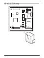
Main Board [PK-950B] ......................................................................................................... 5-2
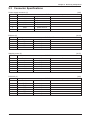
Connector Specifications ..................................................................................................... 5-3
PK-229A (A/D board) ........................................................................................................... 5-7
Lithium Battery ..................................................................................................................... 5-7
Power Unit (PB-LSF150-S) .................................................................................................. 5-8
PK-232 (TCP/IP) .................................................................................................................. 5-9
PK-236A (Span switch) ...................................................................................................... 5-10
P-862A (Key board) ........................................................................................................... 5-10
vii
AC-4000D Service Manual
No. 085-7322-04
Contents
CHAPTER 6 TROUBLESHOOTING
6.1
6.2
Error List .............................................................................................................................. 6-1
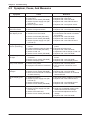
Symptom, Cause, And Measures ........................................................................................ 6-4
CHAPTER 7 PARTS REPLACEMENT
7.1
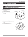
Removing the covers ........................................................................................................... 7-1
Removing the main unit cover ........................................................................................... 7-1
Removing the controller unit rear cover ............................................................................ 7-1
Detach the weigh platter ................................................................................................... 7-2
Detaching the platter holder .............................................................................................. 7-2
7.2 Detaching Internal Parts ...................................................................................................... 7-3
Detaching the keyboard relay board (P-862A) .................................................................. 7-3
Detaching the key sheet .................................................................................................... 7-3
Detaching the display ........................................................................................................ 7-3
Detaching the power supply .............................................................................................. 7-4
Detaching the span switch (PK-236A) .............................................................................. 7-4
Detaching the PK-232 (TCP/IP) ........................................................................................ 7-4
4-corner limit adjustment ................................................................................................... 7-5
Detaching the PK-229A (A/D board) ................................................................................. 7-5
Detaching the PK-950B (Main board) ............................................................................... 7-6
Detaching the thermal head .............................................................................................. 7-7
Cleaning the thermal head ................................................................................................ 7-8
Adjusting the belt tension .................................................................................................. 7-8
Cleaning the label sensor/peel sensor .............................................................................. 7-8
7.3 Periodical Replacement Parts ............................................................................................. 7-9
AC-4000D Service Manual
No. 085-7322-04
viii
Chapter 1 Overview
CHAPTER
1
OVERVIEW
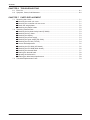
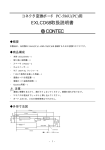
1.1 Appearance and Name of Each Part
Main unit
Control unit
Display
Key sheet
Upper surface: Operation key sheet
Lower surface: Program key sheet
Printer
Weigh platter
Weigher unit
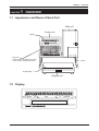
1.2 Display
ZERO
PEEL
MASS
NET
kg
SAVE
AUTO
R/kg
1-1
PLU
R
AMOUNT
AC-4000D Service Manual
No. 085-7322-04
Chapter 1 Overview
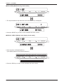
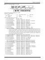
1.3 Key Sheet
/'55#)'
'&+6(70%6+105
2(
'
2.7
5614'
$#4
-';5
6+/'
.+56
0#/'
%1&'
'
1'
+
0
%
Έ
#'
̉
㧏
㧐
㧑
㧒
㧛
3
9
'
4
6
;
7
#
5
&
(
)
*
.19'4
<
:
%
8
$
':64#
6':6
%17210
6':6
#&8
/5)
4'21460#/'5
&'26
#
㧍
%#5'
)4172
12'4#614
㨪
1
̍
ޔ
ޔ
'
'
$5
%*#4
&'.'6'
.+0'
&'.'6'
+05'46
)4#0&
&#+.;
616#.
5#.'5
014/#.
+6#.+%
+
1
2
,
-
.
0
/
㨪
70&'4
.+0'
4'8'45'
4'5'6
/1&'
$1.&
5+<'
%12;
24+%'
#&8
'&+6
2#2'4
%*#0)'
24+%'
2.7
(''&
!
"
24+06
2.7
%.4
6#4'
'06'4
0'9
52#%'
'&+6
.+0'
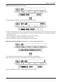
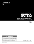
1.4 Printer
Label holding shaft
Release lever
Print head
U-pin
Label guide
Winding sleeve
Peeling bar
Label sensor
Printer unit
AC-4000D Service Manual
'0&
%*#4#%6'456;.'
Ǫ
5#.'54'21465
5*+(6
*'.2
'&+6(70%6+105
7
<'41
No. 085-7322-04
1-2
Chapter 1 Overview
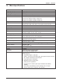
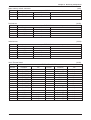
1.5 Main Specifications
Item
Weighing capacity
Minimum graduation
Weighing accuracy
Load cell
Size
Weigh platter material and size
Printer
Label roll size
Label length
Sensor
Key
Display
Operating temperature
Operating humidity
Power supply
Power consumption
Weight
Memory capacity
Interface
TCP/IP
LAN cable
SRAM
Content
6kg, 15kg or 30lb
2g, 5g or 0.01 lb
1/3000 (Dual interval)
HBM made
Main unit: 200(W) x 370(D) x 400(H) mm
Control unit: 320(W) x 40(D) x 322(H) mm
Weigher unit: 400(W) x 254(D) x 95(H) mm
SUS430...400(W) x 250(D) mm
Backing paper width...Max. 67mm, Label width...38 to 64mm,
Effective print width...Max. 60mm, Print speed...80mm/second
Inner diameter: 76mm
30 to 240mm
Peel sensor
Membrane switch (120 keys)
Fluorescent display tube: 23 digits
Character height: 10.1mm, 256 x 16 dots
-5 to 40°C
Main body: Max. 95% (40°C), No condensation
Printer: Max. 80% (40°C), No condensation
Varies depending on where the machine is used.
(Specified on the rating plate)
Stand-by: Approx. 40W
Operating: Approx. 100W
Main unit: 10.5kg / Control unit: 3kg / Weigher unit: 6kg
Standard: 1MB
Factory option: 2MB
RS232C (D-sub 9 pin)
10 baseT
Direct connection: Crossing cable
When using Hub: Straight cable
1M bytes (1,024k bytes)
SRAM mapping
1. Fixed data: Approx. 19k bytes
Approx. 1k bytes for fixed data year, print speed, and print density,
etc., and the remainder is the reserves.
2. Logo data: Approx. 56k bytes
3. SRAM file: Approx. 949k bytes
949k bytes for registration
9k bytes for file creation (940k bytes available after RAM is
cleared)
PLU, Store name/address, Extra message 1/2/3, Coupon,
Preset, Label format, Field title, and Operator
1-3
AC-4000D Service Manual
No. 085-7322-04
Chapter 1 Overview
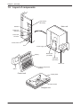
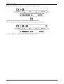
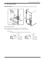
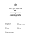
1.6 Layout of components
Span switch
(PK-236A)
Main unit
RS232C
TCP/IP port
(PK-232)
Control unit
connector
Power switch
Fuse
Power supply
Main board
(PK-950B)
Display
A/D board
(PK-229A)
Printer unit
Keyboard relay board
(P-862A)
Stand
Control unit
Weigh platter
Platter holder
Weigher unit
AC-4000D Service Manual
No. 085-7322-04
1-4
Chapter 2 Installation
CHAPTER
2
INSTALLATION
2.1 Packed Goods
Open the packing case and check whether there are all the packed goods (machine and attachments)
and if there are any damaged parts.
1. Operation manual,
Keysheet
1
2. Control unit
2
3. Screws
4. Thermal head cleaner
5. Stand
6. Weigher unit
7. Main unit
3
4
6
5
7
2-1
AC-4000D Service Manual
No. 085-7322-04
Chapter 2 Installation
2.2 Installation Environment
• Install the machine on the stable and horizontal place.
• Install the machine in the place where the liquid such as water does not splash.
• Avoid the place where direct sunshine strikes for a long time.
• Install the machine in the place where the influence such as the winds is not received.
• Secure the installation space enough.
400mm
322mm
95mm
320mm
200mm
400mm
370mm
254mm
40mm
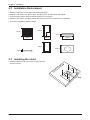
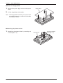
2.3 Installing the stand
• Install the stand on the rear of the control unit with
the four screws.
AC-4000D Service Manual
No. 085-7322-04
2-2
Chapter 2 Installation
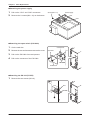
2.4 Connecting the cable
• Insert the control unit cable connector into the port
at the rear of the main unit and secure it.
Main unit
(rear side)
• Insert the weigher cable connector of the main unit
into the port of the weigher unit.
Weigher unit
(rear side)
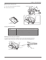
2.5 Label Loading
1 Open the side and printer covers of the main unit.
Printer cover
Side cover
2 Pull
the release lever to raise the print head.
Print head
Release lever
2-3
AC-4000D Service Manual
No. 085-7322-04
Chapter 2 Installation
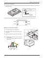
3 Remove labels from first 30 cm (12inches) of back-
30
cm
ing paper.
4 Slide a new label roll onto the label holding shaft,
and pass the labels through the label sensor and
the printer unit as shown on the right.
Label holding shaft
Release lever
Print head
U-pin
Label guide
Winding sleeve
Peeling bar
Label sensor
Printer unit
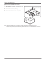
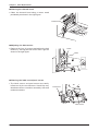
5 Secure the end of the backing paper to the winding sleeve with a U-pin.
Winding
sleeve
6 Depress the print head until it locks securely.
7 Close the side and printer covers.
AC-4000D Service Manual
No. 085-7322-04
2-4
U-pin
Chapter 2 Installation
2.6 Power Cable Connection
• Insert the power cable plug into the power outlet.
Note: The power outlet shape varies according to customers.
Power outlet
Power cord
Ensure to establish a ground at the customer side.
110 V /220 V input power supply can be used. However, set the jumper lead to the required
voltage display side before the power is turned ON.
Power supply
(PB-LSF150-S)
110V
220V
2.7 Power Switch “ON”
• Turn on the power switch located at the rear side
of main unit.
Note: Push the “O” side of the switch to urn off the
power.
ON
OFF
2-5
AC-4000D Service Manual
No. 085-7322-04
Chapter 2 Installation
2.8 Customer’s Specification Setup
(Initialization, Setup, and Registration)
Set up required specifications according to the following sequence.
Test mode (Refer to Chapter 3 “Test Mode”)
⎯⎯⎯⎯⎯⎯⎯⎯⎯ 1. Hardware test ................................................................ P.3-2
⎯⎯⎯⎯⎯⎯⎯⎯⎯ 2. RAM clear ..................................................................... P.3-7
⎯⎯⎯⎯⎯⎯⎯⎯⎯ 3. Printer head .................................................................. P.3-11
⎯⎯⎯⎯⎯⎯⎯⎯⎯ 4. Label sensor check ....................................................... P.3-13
⎯⎯⎯⎯⎯⎯⎯⎯⎯ 5. Total memory ................................................................. P.3-14
⎯⎯⎯⎯⎯⎯⎯⎯⎯ 6. ROM switch ................................................................... P.3-15
⎯⎯⎯⎯⎯⎯⎯⎯⎯ 7. Peel sensor check ........................................................ P.3-17
8. Machine type check ...................................................... P.3-18
Setup mode (Refer to Chapter 4 “Setup Mode”)
⎯⎯⎯⎯⎯⎯⎯⎯⎯ 1. Label format .................................................................. P.4-3
⎯⎯⎯⎯⎯⎯⎯⎯⎯ 2. POS code ...................................................................... P.4-10
⎯⎯⎯⎯⎯⎯⎯⎯⎯ 3. Item code ...................................................................... P.4-13
⎯⎯⎯⎯⎯⎯⎯⎯⎯ 4. Default data ................................................................... P.4-14
⎯⎯⎯⎯⎯⎯⎯⎯⎯ 5. Total mode select .......................................................... P.4-16
⎯⎯⎯⎯⎯⎯⎯⎯⎯ 6. Open price..................................................................... P.4-17
⎯⎯⎯⎯⎯⎯⎯⎯⎯ 7. PLU selection ................................................................ P.4-18
⎯⎯⎯⎯⎯⎯⎯⎯⎯ 8. System .......................................................................... P.4-26
⎯⎯⎯⎯⎯⎯⎯⎯⎯ 9. Ethernet setup ............................................................... P.4-31
⎯⎯⎯⎯⎯⎯⎯⎯⎯ 10. System timer ................................................................. P.4-39
⎯⎯⎯⎯⎯⎯⎯⎯⎯ 11. Password setup ............................................................ P.4-40
12.Machine number setup ................................................. P.4-42
AC-4000D Service Manual
No. 085-7322-04
2-6
Chapter 2 Installation
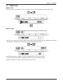
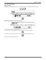
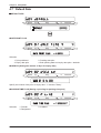
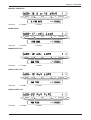
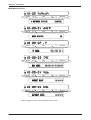
2.9 Normal Mode Display
1.
All segments blink three times when the power is turned on.
MASS
kg
R/kg
R
AMOUNT
9'9+..5'48';175*146.;
2.
Then, the initial display appears.
MASS
kg
R/kg
R
AMOUNT
R
AMOUNT
R
AMOUNT
-';+0+6'/0Q
3.
When calling up “Fixed price item” or “Weighing item”.
Weighing item
MASS
kg
R/kg
6'56+6'/#
Fixed price item
MASS
kg
R/kg
6'56+6'/#
2-7
AC-4000D Service Manual
No. 085-7322-04
Chapter 2 Installation
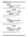
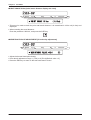
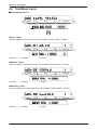
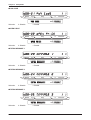
2.10 Label Batch Print Mode
• The following display appears when printing batches of labels.
• The label batch printing is a function which prints the item data and the number of labels registered in
advance a for fixed price items.
MASS
kg
R/kg
R
AMOUNT
2.7
%1706
• Maximum number of specified items: 99 commodities
• Maximum number of specified labels: 9,999 labels
• Preset key number: 19 presets
Note: Registered data is cleared when the power is turned OFF.
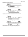
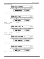
2.10.1 Basic operation
• Assign the BATCH PRINT key (Preset key number: 19) to any one of preset keys.
P04-01 screen menu ..... 19 + [→] + 0 + Preset key
MASS
kg
R/kg
R
AMOUNT
24'5'6-';(.).#$'.$#6%*
24'5'6-';(.).#$'.$#6%*
• Press the LABEL BATCH key to enter the label batch print mode.
This function is available before an item is called up.
1.
Call up a fixed price item.
Key in an item number, then press the PLU key.
Note: An error buzzer sounds when other item is called than fixed price item.
2.
Specify the number of labels to be printed.
Key in the number of labels, then press the ENTER key.
Note: An error buzzer sounds when the limited number of labels (9,999 labels) exceeds.
3.
Repeat above steps 1. and 2. to specify the number of labels for other items.
Note: An error buzzer sounds when exceeding the maximum number of specified items (99 items).
4.
Press the PRINT key to start printing. Then, printing starts in the sequence from the most recently
registered item.
Note: An error buzzer sounds when there is no item registered for label batch printing.
5.
The machine returns to the normal mode after all registered items are printed.
AC-4000D Service Manual
No. 085-7322-04
2-8
Chapter 2 Installation
2.10.2 Additional functions
1.
End of the label batch print mode
The machine returns to the normal mode when the MODE key is pressed.
The registered data is preserved as it is if there are any registered items.
2.
Printing preserved data
If there is any preserved print data, printing starts by pressing the PRINT key.
Note: An error buzzer sounds if there is no registered data.
Deleting label batch print data
The label batch print data is deleted while sounding an OK buzzer by pressing the ZERO key twice.
3.
4.
Stop of label batch print operation
Label batch print stops by pressing the PRINT key while printing a print reservation data.
However, the remaining label batch print items are not deleted.
(If printing stops when five labels have been issued for an item specified to issue 10 labels, the
remaining 5 labels are preserved.)
5.
Addition of label batch print data to the preserved data
The label batch print data is added to the preserved data.
(When there are “40 preserved items”, “59 items” can be added.)
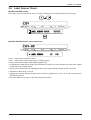
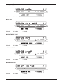
2.10.3 Label batch printing on continuous paper
The same operation is applied for continuous paper which is set in the B01-01-05 menu.
Refer to 4-4 in Chapter 4.
MASS
kg
R/kg
R
AMOUNT
.#$'.&+'%76%106+07175
2-9
AC-4000D Service Manual
No. 085-7322-04
Chapter 2 Installation
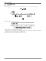
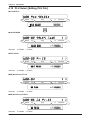
2.11 Scroll Message Display
• A function to display the registered scroll message. When an item has not been called up, it starts after
five seconds have passed.
MASS
kg
R/kg
R
AMOUNT
#$%&'()*+,-./0123456789:;<
• Display method registration function
(0: No display
1: High-speed scroll
4: High-speed blinking
5: Normal blinking
2: Normal scroll
6: Low-speed blinking)
3: Low-speed scroll
• Day of the week registration function
(0: Every day 1: Sunday 2: Monday 3: Tuesday 4: Wednesday 5: Thursday 6: Friday 7: Saturday)
• Display time registration function (Start/stop)
[Example]
09:00 to 13:00
Enter “0913” and press the ENTER key.
• Maximum number of scroll messages: 9 messages (1 to 9)
• Maximum number of characters: 96 characters (one byte English code)
2.12 Campaign Function
• Registered campaign items start to be sold at the registered campaign price when the time reaches
registered campaign time.
• Maximum number of campaign: 20
• Maximum number of items for each campaign: 100
• Discount method
(0: Unit price 1: Special price 2: Amount discount 3: Percent discount 4: Special unit price)
• Campaign 1 becomes top priority for items registered during the overlapping time.
• Priority is given from Campaign 1, 2, and 3 to the last 20 if the same item is registered.
That is, priority is given to the campaign 1 even if the same item is registered in campaign 1 and 2
during the overlapping time.
• Registration of the same item is not supported in one campaign.
• An error message appears when a label is issued with a registered price in the campaign greater than
the weighing price.
AC-4000D Service Manual
No. 085-7322-04
2-10
Chapter 3 Test Mode
CHAPTER
3
TEST MODE
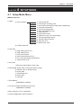
3.1 Test Mode Menu List
Hardware test
⎯⎯⎯⎯⎯⎯⎯⎯⎯ a) A/D check ...................................................................... P. 3-2
⎯⎯⎯⎯⎯⎯⎯⎯⎯ b) Key check ..................................................................... P. 3-4
⎯⎯⎯⎯⎯⎯⎯⎯⎯ c) Display check ................................................................ P. 3-4
⎯⎯⎯⎯⎯⎯⎯⎯⎯ d) RS232C check .............................................................. P. 3-5
⎯⎯⎯⎯⎯⎯⎯⎯⎯ e) Application program number ......................................... P. 3-5
⎯⎯⎯⎯⎯⎯⎯⎯⎯ f) BIOS program number .................................................. P. 3-6
RAM clear
⎯⎯⎯⎯⎯⎯⎯⎯⎯ a) RAM clear ..................................................................... P. 3-7
⎯⎯⎯⎯⎯⎯⎯⎯⎯ b) Setup clear .................................................................... P. 3-8
⎯⎯⎯⎯⎯⎯⎯⎯⎯ c) Test data set .................................................................. P. 3-8
⎯⎯⎯⎯⎯⎯⎯⎯⎯ d) Application copy ............................................................ P. 3-9
⎯⎯⎯⎯⎯⎯⎯⎯⎯ e) BIOS copy ..................................................................... P. 3-9
Printer head
⎯⎯⎯⎯⎯⎯⎯⎯⎯ a) Resistance .................................................................... P. 3-11
⎯⎯⎯⎯⎯⎯⎯⎯⎯ b) Print usage in km .......................................................... P. 3-12
⎯⎯⎯⎯⎯⎯⎯⎯⎯ c) Resistance value ........................................................... P. 3-12
Label sensor check
⎯⎯⎯⎯⎯⎯⎯⎯⎯ • Level sensor .................................................................. P. 3-13
Total memory
⎯⎯⎯⎯⎯⎯⎯⎯⎯ • Total Memory ................................................................. P. 3-14
ROM switch
⎯⎯⎯⎯⎯⎯⎯⎯⎯ • ROM switch ................................................................... P. 3-15
⎯⎯⎯⎯⎯⎯⎯⎯⎯ • ROM switch number ..................................................... P. 3-15
Peel sensor check
⎯⎯⎯⎯⎯⎯⎯⎯⎯ • Peel sensor check ........................................................ P. 3-17
⎯⎯⎯⎯⎯⎯⎯⎯⎯ • Peel sensor ................................................................... P. 3-17
Machine type check
⎯⎯⎯⎯⎯⎯⎯⎯⎯ • Hardware selection ....................................................... P. 3-18
3-1
AC-4000D Service Manual
No. 085-7322-04
Chapter 3 Test Mode
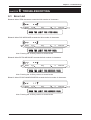
3.2 Test Mode Start
Reset the main power or press the RESET key, then immediately press and keep pressing any key other
than the RESET key for a while until a buzzer sounds, the following test mode menu screen will appear by
releasing the key.
any key
MASS
kg
R/kg
R
AMOUNT
6'56/1&'24'55=?-';
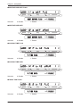
3.3 Hardware Test
HARDWARE TEST
To select a desired menu, press the key to increment a menu, or enter a menu number followed by
pressing the [↓] key.
MASS
kg
R/kg
R
AMOUNT
*#4&9#4'6'56='06'4?
*#4&9#4'6'56='06'4?
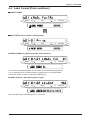
A/D CHECK [Scale zero point/span check and adjustment]
• In the [C01] display, press the ENTER key to select the A/D CHECK menu.
(It will take a few seconds until the A/D board is initialized.)
MASS
kg
R/kg
R
AMOUNT
#&%*'%-='06'4?
AC-4000D Service Manual
No. 085-7322-04
3-2
Chapter 3 Test Mode
• Firstly, the A/D original data appears.
MASS
kg
R/kg
R
AMOUNT
<'41=<'41?52#0=6#4'?
• Pressing the ZERO key changes to the calibrated data of “20000” counts and “0”.
(“20000” counts is a data output from the A/D unit, and “0” denotes that “20000” counts are regarded as
zero point.)
Zero point adjustment screen
MASS
kg
R/kg
R
AMOUNT
<'41=<'41?52#0=6#4'?
• In “C01-01-00” menu and after a zero point adjustment, put the same weight as the maximum weighing
capacity and press the TARE key to perform an auto-span.
Span adjustment screen
MASS
kg
R/kg
R
AMOUNT
<'41=<'41?52#0=6#4'?
• After the span adjustment, finish to check the zero point and the weighing capacity value by repeating
zero point and span adjustments.
• After completing the span adjustment, push the memory button on the board to store the adjustment
value in E2ROM.
• When initializing E2ROM of the A/D circuit to the initial value, press the DEL key to initialize.
• When E2ROM storage completes, press the END key to return to the hardware test menu screen.
Note 1: Changed data is cleared at the end of this menu unless it is stored in E2ROM by pushing the
memory button.
Note 2: The memory button is described in “Chapter 5”.
3-3
AC-4000D Service Manual
No. 085-7322-04
Chapter 3 Test Mode
KEY CHECK [Membrane key check mode]
MASS
kg
R/kg
R
AMOUNT
-';%*'%-='06'4?
• The input membrane key data other than the RESET key is displayed.
MASS
kg
R/kg
R
AMOUNT
-';%*'%--';#
• Press the RESET key to return to the hardware test menu screen.
DISPLAY CHECK [Multiple tube display check mode]
MASS
kg
R/kg
R
AMOUNT
&+52.#;%*'%-='06'4?
• Each segment of all digits lights up.
(This display flashes in one second interval.)
MASS
kg
R/kg
• Press the END key to return to the hardware test menu screen.
AC-4000D Service Manual
No. 085-7322-04
3-4
R
AMOUNT
Chapter 3 Test Mode
RS232C CHECK [Driver/receiver test]
MASS
kg
R/kg
R
AMOUNT
45%%*'%-='06'4?
• Serial output port (RS232C) driver/receiver test menu screen
MASS
kg
R/kg
R
AMOUNT
45%%*'%-=24+06?=?
• Perform a loop back test to carry out the RS232C input test. Engage the TXD and RXD short-circuited
connector with D-SUB 9, press the PRINT key to output test data, and judge by verifying received test
data and sent data.
If the data matches, “PASS” is displayed and “OK” buzzer sounds.
“Error” is displayed and “NG” (No Good) buzzer sounds.
• Press the END key to return to the hardware test menu screen.
APPLICATION PROGRAM No. [Program no. and version display check]
MASS
kg
R/kg
R
AMOUNT
#22.+%#6+10241)4#/0Q='06'4?
• The program number and version of the main program are displayed.
Note: The program number for the prototype is the development code “APLY”.
MASS
kg
R/kg
R
AMOUNT
241)4#/0Q#22.;$%
• Press the END key to return to the hardware test menu screen.
3-5
AC-4000D Service Manual
No. 085-7322-04
Chapter 3 Test Mode
BIOS PROGRAM No. [Program no. and version display check]
MASS
kg
R/kg
R
AMOUNT
$+15241)4#/0Q='06'4?
• Program number and version of the BIOS program are displayed.
Note: The program number for the prototype is the development code “BOOT”.
MASS
kg
R/kg
R
AMOUNT
241)4#/0Q$+15$#
• Press the END key to return to the hardware test menu screen.
AC-4000D Service Manual
No. 085-7322-04
3-6
Chapter 3 Test Mode
3.4 RAM Clear
RAM CLEAR
Press the [↓] key to increment a menu, or enter a menu number followed by pressing the [↓] key.
MASS
kg
R/kg
R
AMOUNT
4#/%.'#4='06'4?
4#/%.'#4='06'4?
SRAM CLEAR
MASS
kg
R/kg
R
AMOUNT
54#/%.'#4=?
• This menu is used when clearing SRAM. When this menu is executed, all the SRAM data is cleared
(initialization). SRAM clear is executed by pressing the ZERO key twice.
MASS
kg
R/kg
R
AMOUNT
54#/%.'#4=1-?
• When SRAM clear is complete, “PASS” is displayed and “OK” buzzer sounds.
• If an error is detected, “ERR” is displayed and “NG” (No Good) buzzer sounds.
• Press the END key to return to the test mode menu screen.
3-7
AC-4000D Service Manual
No. 085-7322-04
Chapter 3 Test Mode
SETUP CLEAR [E2ROM default]
MASS
kg
R/kg
R
AMOUNT
5'672%.'#4=?
• This menu is used when initializing E2ROM to a default value. When this mode is executed, the content
of the E2ROM switch is initialized to default. SRAM clear is executed by pressing the ZERO key twice.
MASS
kg
R/kg
R
AMOUNT
5'672%.'#4=1-?
• When processing is complete, “PASS” is displayed and “OK” buzzer sounds.
• If an error is detected, “ERR” is displayed and “NG” (No Good) buzzer sounds.
• Press the END key to return to the test mode menu screen.
TEST DATA SET
MASS
kg
R/kg
R
AMOUNT
6'56#5'6=?
• This menu is used when setting up the machine for the first time (when there is no backup data).
• In this mode, execute a set of SRAM clear + E2ROM setup + Dummy data creation.
• The dummy data memorizes 10 PLU data and the store name/address.
• SRAM clear is executed by pressing the ZERO key twice.
MASS
kg
R/kg
R
AMOUNT
6'56#5'6=1-?
• When processing is complete, “PASS” is displayed and “OK” buzzer sounds.
• When an error is detected, “ERR” is displayed and “NG” (No Good) buzzer sounds.
• Press the END key to return to the test mode menu screen.
AC-4000D Service Manual
No. 085-7322-04
3-8
Chapter 3 Test Mode
APPLICATION COPY [Writing application]
MASS
kg
R/kg
R
AMOUNT
#22.+%#6+10%12;=?
• Write the application part of flash ROM. [1M byte]
MASS
kg
R/kg
R
AMOUNT
#22.+%#6+10%12;=1-?
• When processing is complete, “PASS” is displayed and “OK” buzzer sounds.
• When an error is detected, “ERR” is displayed and “NG” (No Good) buzzer sounds.
BIOS COPY [Writing boot program]
MASS
kg
R/kg
R
AMOUNT
$+15%12;=?
• Write the boot program part of flash ROM. [512k byte]
MASS
kg
R/kg
R
AMOUNT
$+15%12;=1-?
• When processing is complete, “PASS” is displayed and “OK” buzzer sounds.
• When an error is detected, “ERR” is displayed and “NG” (No Good) buzzer sounds.
3-9
AC-4000D Service Manual
No. 085-7322-04
Chapter 3 Test Mode
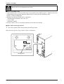
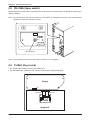
BIOS COPY is not displayed in test mode.
When using BIOS COPY
• If the machine locks, or the test mode entry is not possible, enter [APPLY COPY] → [BIOS COPY] and
a transmission end message appears in [BIOS COPY], then press the ZERO key twice.
[EXEC] + [PASS] is displayed.
• Standing up state after BIOS COPY is operated.
• Internet Protocol address: 192. 168. 10. 1
• Log-in: TEST
• Password: USNET
• Perform “APPLI COPY” in the same operation as the above-mentioned.
BOOT COPY starting procedure
1.
Turn on the power switch while pushing the Memory button.
Note: Press the [↓] key. Then, “BOOT COPY” is displayed.
J1
SW1
PK-236A
Memory button
AC-4000D Service Manual
No. 085-7322-04
3-10
Chapter 3 Test Mode
3.5 Printer Head
PRINTER HEAD
Press the [↓] key to increment a menu, or enter a desired menu number followed by the [↓] key.
MASS
kg
R/kg
R
AMOUNT
24+06*'#&='06'4?
24+06*'#&='06'4?
RESISTANCE [Thermal head resistance value]
MASS
kg
R/kg
R
AMOUNT
4'5+56#0%'
• Set a resistance value of the thermal head.
• Press the COPY key to read ID from the thermal head and set it automatically.
Or, enter a resistance value described on the head followed by the ENTER key.
• Stored data is memorized in E2ROM.
3-11
AC-4000D Service Manual
No. 085-7322-04
Chapter 3 Test Mode
PRINT USAGE IN km [Label travel distance display and clear]
MASS
kg
R/kg
R
AMOUNT
24+0675#)'+0MO
MO
• This menu is used to check the print total travel distance. It is memorized in 100m unit (0.1km) and
displayed.
• When resetting the travel distance:
Enter the password “495344”, and press the SIZE key.
RESISTANCE VALUE ADJUSTMENT [Print density adjustment]
MASS
kg
R/kg
R
AMOUNT
4'5+56#0%'8#.7'#&,
• Adjust the thermal head print density.
• Print density adjustment range: 1 (Thin) to 9 (Thick) [Default value = 5]
• Press the END key to return to the test mode menu screen.
AC-4000D Service Manual
No. 085-7322-04
3-12
Chapter 3 Test Mode
3.6 Label Sensor Check
LABEL SENSOR CHECK
Press the [↓] key to increment a menu, or enter a desired menu number followed by the [↓] key.
MASS
kg
R/kg
R
AMOUNT
.#$'.5'0514%*'%-='06'4?
.#$'.5'0514%*'%-='06'4?
LABEL SENSOR [Output value adjustment]
MASS
kg
R/kg
R
AMOUNT
.#$'.5'0514
• [32 ] : Label sensor resistance value
• [33 ] : Label sensor output value (Label + Baking paper)
• [140] : Label sensor output value (Baking paper only)
• At adjustment: Label sensor output value deviation must be 50 or more between the case when a label
exists and when no label exists.
• Output from the label sensor is displayed with a value after passing through the A/D converter.
• Adjustment value range: 0 to 255
• Adjustment method: Adjust the label sensor volume in digital form. Key in “0 to 255” and press the
ENTER key to store.
• Press the END key to return to the test mode menu screen.
3-13
AC-4000D Service Manual
No. 085-7322-04
Chapter 3 Test Mode
3.7 Total Memory
TOTAL MEMORY
Press the [↓] key to increment a menu, or enter a desired menu number followed by the [↓] key.
MASS
kg
R/kg
R
AMOUNT
616#./'/14;='06'4?
616#./'/14;='06'4?
MEMORY [Memory usage status]
MASS
kg
R/kg
R
AMOUNT
/'/14;=-$?4'/#+0=-$?
• A total memory and a free memory are displayed.
• A free memory is not necessarily corresponding to the remaining amount which can be stored, because
it indicates only the one that the block is completely free.
• Press the END key to return to the test mode menu screen.
AC-4000D Service Manual
No. 085-7322-04
3-14
Chapter 3 Test Mode
3.8 ROM Switch
ROM SWITCH
Press the [↓] key to increment a menu, or enter a desired menu number followed by the [↓] key.
MASS
kg
R/kg
R
AMOUNT
41/59+6%*='06'4?
41/59+6%*='06'4?
ROM SWITCH No. [E2ROM switch change and check]
MASS
kg
R/kg
R
AMOUNT
41/59+6%*0Q5'.'%6=?
• Change or check the E2ROM switch in this menu.
• Multiple tube display “LL”, “HH”, “XX”
”LL” indicates the E2ROM address.
”HH” indicates the E2ROM address data.
”XX” monitors the input data.
• To specify an address, use the arrow keys.
• To change a data, enter hexadecimal numerics by using the alphabet of [A to F] and numerics of [0 to 9].
• Press the END key to return to the test mode menu screen.
3-15
AC-4000D Service Manual
No. 085-7322-04
Chapter 3 Test Mode
ROM SWITCH No.
Note: “ROM SWITCH” items and default value vary depending on a country where the machine is used.
• Value in ( ) indicates the default value.
[0]: Weight data zero suppression (4)
[1]: Price data zero suppression (3)
[2]: Unit price data zero suppression (3)
[3]: DC motor (41)
[4]: Fixed price item quantity addition “0”: Real number “1”: Fixed price item quantity
[5]: Price calculation rate “0”: kg “1”: 100g
[7]: Effective day calculation
When ROM SWITCH No.7 is “0”, packed date is included. When ROM SWITCH No.7 is other
numeric than “0”, packed date is not included, therefore, add one day to the current effective day.
[8]: Time rounding calculation 0, 1 to 30 (0)
Function to increase the price based on the set minute at time now is set by standard.
(Minute/No. 8) * No. 8
[Example]
◊
Example: No. 8 = 1 min.
1 → 1 min., 2 → 2 min., ..... 59 → 59 min.
◊
Example: No. 8 = 2 min.
1 → 0 min., 2 → 2 min., 3 → 2 min., 4 → 4 min., 5 → 4 min., ..... 58 → 58 min., 59 → 58 min.
◊
Example: No. 8 = 3 min.
1 → 0 min., 2 → 0 min., 3 → 3 min., 4 → 3 min., 5 → 3 min., 6 → 6 min., ..... 57 → 57 min.
58 → 57 min., 59 → 57 min.
.
.
◊
Example: No. 8 = 30 min.
1 → 0 min., 2 → 0 min., 3 → 0 min., 4 → 0 min., 5 → 0 min., 6 → 0 min.
29 → 0 min., ..... 30 → 30 min., 31 → 30 min., ..... 59 → 30 min.
[9]: Subtotal label item name mode
0 : “sub total“ is printed.
1: Item name is printed when an item is called.
[10]: Reset key 0: Enable 1: Disable (0)
[11]: Automatic clear after totals are sent out
0: Not cleared (default) 1: Clear
[15]: Price calculation fraction processing (0)
0: 3rd decimal digit round-down 1: 3rd decimal digit round off
2: 2nd decimal digit round-down 3: 2nd decimal digit round off
[16]
ITF BARCODE check digit calculation processing (0)
0: 3131. . . . . from the right 1: 1313. . . . . from the right
[17]: Head fault check (0)
0: Not available 1: Available (Set “0” for ASTRA XT)
[18]: Head fault check timing (0)
0: When calling 1: When issuing (no provision) ff: Only when changing to normal mode
[19]: Head check type (0)
0: Always at the head fault
AC-4000D Service Manual
1: When the number of head fault increases.
No. 085-7322-04
3-16
Chapter 3 Test Mode
3.9 Peel Sensor Check
PEEL SENSOR CHECK
Press the [↓] key to increment a menu, or enter a desired menu number followed by the [↓] key.
MASS
kg
R/kg
R
AMOUNT
2''.5'0514%*'%-='06'4?
2''.5'0514%*'%-='06'4?
PEEL SENSOR [Output value is checked]
MASS
kg
R/kg
R
AMOUNT
2''.5'0514
• Sensor value display
[255]: Peel sensor resistance
[255]: Peel sensor resistance
[186]: Peel sensor output value (Label + Backing paper)
[0] : Peel sensor output value (Backing paper only)
• Output from the peel sensor is displayed with a value after passing through the A/D converter.
• Setting range: 0 t o 255
• Input method: Key in 0 to 255, and press the ENTER key to store.
• Press the END key to return to the test mode menu screen.
3-17
AC-4000D Service Manual
No. 085-7322-04
Chapter 3 Test Mode
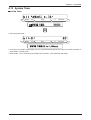
3.10 Machine Type Check
MACHINE TYPE SET [Hardware selection by specifying the machine type flag]
Press the [↓] key to increment a menu, or enter the desired menu number followed by the [↓] key.
MASS
kg
R/kg
R
AMOUNT
/#%*+0'6;2'5'6='06'4?
/#%*+0'6;2'5'6='06'4?
MASS
kg
R/kg
R
AMOUNT
/#%*+0'6;2'5'6#%&
0: AC-4000B
1: AC-4000
2: AC-4000D
3: AC-4000H
4: AC-4000E
AC-4000D Service Manual
No. 085-7322-04
3-18
Chapter 4 Setup Mode
CHAPTER
4
SETUP MODE
4.1 Setup Mode Menu
Setup menu list
• Labels
a) Print condition
1. Label format No.
2. Label length including pitch
3. Item name returning line width (when registering)
4. Label sensor distance
5. Continuous paper label
6. Store name/address print
7. Field title print
8. Peel sensor mode
9. Default PLU (PLU for test printing)
10. Thermal head fault check
11. Subtotal label format No.
12. Store No. print
13. Machine No. print
b) Label format edit
• POS code
a)
b)
c)
d)
e)
f)
Flag setting (Non-PLU)
Flag setting (PLU)
POS code system
POS code type (Non-PLU)
ITF code type (China specification)
Manufacturer code
• Item code
⋅ Reference data position in bar code
• Default data (Initial value of external reference data)
a)
b)
c)
d)
e)
Default value of date print flag
Expiry date
Processing time
Expiry time
Unit type
• Total addition
⋅ Available/Not available
• Unit price change prohibition (open price)
⋅ Available/Not available
• Menu selection of PLU registration
• System (Registration menu selection)
4-1
AC-4000D Service Manual
No. 085-7322-04
Chapter 4 Setup Mode
• Ethernet setting
a)
b)
c)
d)
e)
f)
g)
h)
i)
IP address
Gateway address setup
Subnet mask setup
Server address setup
Log-in name setup
Password setup
Mac address setup
DHCP setup
Network status
• System timer
• Password setting
a)
b)
c)
d)
e)
Password
Registration
Total
Subtraction
Setup
4.2 Starting Procedure for Each Mode
•
•
•
•
Setup mode:
Subtraction:
Total:
Registration:
Enter “6000”, and press the MODE key.
Enter “7000”, and press the MODE key.
Enter “8000”, and press the MODE key.
Enter “9000”, and press the MODE key.
4.3 Starting Procedure for Setup Mode
• Enter “6000”, and press the MODE key to enter SETUP MODE from normal or other mode.
• Press the [↓] key to increment a menu.
Setup mode menu screen
MASS
kg
R/kg
R
AMOUNT
5'672/1&'24'55=?-';
• Press the [↓] key to increment a menu, or enter a desired menu number followed by pressing the [↓]
key.
AC-4000D Service Manual
No. 085-7322-04
4-2
Chapter 4 Setup Mode
4.4 Label Format [Print conditions]
LABEL FORMAT
MASS
kg
R/kg
R
AMOUNT
.#$'.(14/#6='06'4?
.#$'.(14/#6='06'4?
PRINT SETUP [Print condition setting mode]
MASS
kg
R/kg
R
AMOUNT
24+065'672='06'4?
LABEL FORMAT No. [Specifying label format number]
MASS
kg
R/kg
R
AMOUNT
.#$'.(14/#60Q
• #1 to #4" are standard formats. (# 10 to #99 can be additionally registered.)
• # 1 is a default when a format number in which there is no specified data.
• Enter the format number, and press the ENTER key.
LABEL LENGTH + GAP [Setting label length]
MASS
kg
R/kg
R
AMOUNT
.#$'..'0)6*)#2
VQ
Enter the label length and label pitch in 0.1 mm unit.
4-3
AC-4000D Service Manual
No. 085-7322-04
Chapter 4 Setup Mode
LABEL WIDTH [Setting of item name area print width]
MASS
kg
R/kg
R
AMOUNT
.#$'.9+&6*
VQOO
• This reflect an automatic line returning for an item name registration.
• When (0.0) is set, a line returning is carried out automatically based on the default value.
LABEL SENSOR DISTANCE [Setting a distance between label sensor and thermal head]
MASS
kg
R/kg
R
AMOUNT
.#$'.5'0514&+56#0%'
OO
Enter a numerical value in 0.1 mm unit.
LABEL DIE-CUT, CONTINUOUS [Specifying label (Die-cut label/Continuous paper)]
MASS
kg
R/kg
R
AMOUNT
.#$'.&+'%76%106+07175
Selection
0: Die-cut label
1: Continuous labels
STORE NAME, ADDRESS [Specifying whether to print store name/address or not]
MASS
kg
R/kg
R
AMOUNT
5614'0#/'#&&4'55'0#$.'
Selection
0: Disable
AC-4000D Service Manual
1: Enable
No. 085-7322-04
4-4
Chapter 4 Setup Mode
FIELD TITLE PRINT [Specifying whether to print field title in advance or not]
MASS
kg
R/kg
R
AMOUNT
(+'.&6+6.'24+06'0#$.'
Selection
0: No
1:YES
PEEL SENSOR [Setting availability of peel sensor]
MASS
kg
R/kg
R
AMOUNT
2''.5'0514'0#$.'
Selection
0: DISABLE
1: ENABLE
TEST ITEM No. [Specifying PLU number for test print]
MASS
kg
R/kg
R
AMOUNT
6'56+6'/0Q
Enter a PLU number when performing test print.
THERMAL HEAD CHECK [Specifying availability of thermal head fault display]
MASS
kg
R/kg
R
AMOUNT
6*'40#.*'#&%*'%-&+5#$.'
Selection
0: DISABLE (No error display)
1: ENABLE (Error display)
Note: Thermal head is available only when “C06-00” No. 17 of the E2ROM switch is set “1”.
*No. 17 (Head fault check) 0: DISABLE 1: ENABLE
4-5
AC-4000D Service Manual
No. 085-7322-04
Chapter 4 Setup Mode
SUBTOTAL LABEL FORMAT No. [Setting availability of specifying the label format]
MASS
kg
R/kg
R
AMOUNT
57$616#..#$'.(14/#60Q
Enter the format number.
STORE No. PRINT [Setting availability of specifying the shop number]
MASS
kg
R/kg
R
AMOUNT
5614'0Q24+06'0#$.'
Selection
0: DISABLE 1: ENABLE
MACHINE No. PRINT [Setting availability of specifying the machine number]
MASS
kg
R/kg
R
AMOUNT
/#%*+0'0Q24+06'0#$.'
Selection
0: DISABLE 1: ENABLE
AC-4000D Service Manual
No. 085-7322-04
4-6
Chapter 4 Setup Mode
LABEL FORMAT EDIT [Editing label format]
• How to enter label format edit mode.
Enter a password “4141”, and press the SIZE key.
Note: A protection is released when the above operation has been performed.
MASS
kg
R/kg
R
AMOUNT
.#$'.(14/#6'&+6='06'4?
• Enter a label format number, and press the PLU key to call.
MASS
kg
R/kg
R
AMOUNT
(14/#60Q=2.7?'&+6
FORMAT No. + [PLU] [Copying format]
*New label format edit (Example: Format No. 50)
• Enter “50” and press the PLU key to call a label format.
• Enter “1“ and press the COPY key to copy FORMAT No.1 data to FORMAT No.50.
MASS
kg
R/kg
R
AMOUNT
(14/#60Q=2.7?'&+6
4-7
AC-4000D Service Manual
No. 085-7322-04
Chapter 4 Setup Mode
UNIT [X/Y axis position selection]
MASS
kg
R/kg
R
AMOUNT
70+6='06'4?
Press the ENTER key to select X or Y axis position.
“X” AXIS POSITION
MASS
kg
R/kg
R
AMOUNT
:#:+5215+6+10
“Y” AXIS POSITION
MASS
kg
R/kg
R
AMOUNT
;#:+5215+6+10
• Select “X axis position data” or “Y axis position data” using the [→] key.
• Multiple tube display
N00 : Label format unit # (1 to 50)
600 : X axis position is adjusted in 0.1mm unit.
400 : Y axis position is adjusted in 0.1mm unit.
DEFAULT PLU
MASS
kg
R/kg
R
AMOUNT
&'(#7.62.7='06'4?
Specify a default PLU for test print.
AC-4000D Service Manual
No. 085-7322-04
4-8
Chapter 4 Setup Mode
UNIT DATA [Editing the unit data]
MASS
kg
R/kg
R
AMOUNT
70+6#='06'4?
Move the edit position by using [→][←][↑][↓] keys and rewrite the data.
MASS
kg
R/kg
R
AMOUNT
(/60Q7PKV0Q#FFTGUU&CVC
AA: label format number
BB: Unit number (1 to 50)
CC: Address data in the unit
DD: Input data
NUMBER OF UNITS
MASS
kg
R/kg
R
AMOUNT
07/$'41(70+6='06'4?
Specify the total number of units. The number specified here specifies the number of units including the
label format specified at this point.
Specifiable number of units (1 to 50)
MASS
kg
R/kg
R
AMOUNT
07/$'41(70+6
LABEL LENGTH
Set the label length for each label. (This is prioritized over B01-01-02)
Specify the label length and the pitch between labels.
MASS
kg
R/kg
R
AMOUNT
.#$'..'0)6*)#2
VQ
4-9
AC-4000D Service Manual
No. 085-7322-04
Chapter 4 Setup Mode
4.5 POS Code
POS CODE
MASS
kg
R/kg
R
AMOUNT
215%1&'='06'4?
215%1&'='06'4?
POS FLAG 8/3 [Setting a NON PLU flag]
MASS
kg
R/kg
R
AMOUNT
215(.#)
&KIKV
&KIKVU
Set one or two digits if necessary.
10 DIGIT FLAG 8/13 [Setting a PLU flag for source marking]
MASS
kg
R/kg
R
AMOUNT
&+)+6(.#)
&KI
&KI
Set a flag code for source marking.
POS TYPE [Setting a POS type]
MASS
kg
R/kg
R
AMOUNT
2156;2'0102.7
Selection
1: NON PLU 13
3: PLU 13
5: ITF 18
AC-4000D Service Manual
2: NON PLU 8
4: PLU 8
No. 085-7322-04
4-10
Chapter 4 Setup Mode
BAR TYPE [Setting NON PLU 13 code]
MASS
kg
R/kg
R
AMOUNT
$#46;2'((%%%%%
%22222
%&
• Set the POS code type “NON PLU 13 code”.
• Meaning of abbreviation
F
: Flag
(CP): Check price
E : Weight
M
P
Q
: Manufacturer code
: Price
: Quantity
C : Item code
(0) : 0
I
: PLU no.
• POS code type (NON PLU 13 code)
1.
2.
3.
4.
5.
6.
7.
8.
9.
10.
11.
12.
13.
14.
15.
16.
17.
18.
19.
20.
21.
22.
23.
24.
25.
26.
27.
28.
29.
30.
31.
FFCCCCC(CP)PPPP
: Standard 5 digits
FFCCCCCCPPPP
: 2 digit flag + 6 digit code + 4 digit price
FCCCCCC(CP)PPPP
: 1 digit flag + 6 digit code + Check price + 4 digit price
FFCCCCCPPPPP
: 2 digit flag + 5 digit code + 5 digit price
FCCCCCCPPPPP
: 1 digit flag + 6 digit code + 5 digit price
FFCCCC(CP)PPPPP
: 2 digit flag + 4 digit code + Check price + 5 digit price
FFCCCCCCWWWW
: 2 digit flag + 6 digit code + 4 digit weight
FCCCCCCWWWWW
: 1 digit flag + 6 digit code + 5 digit weight
FCCCCCIIIIII
: 1 digit flag + 5 digit code + 6 digit PLU
FFCCCCCCPPPP
: 2 digit flag + 6 digit code + 4 digit price EAN
FFCCCCCCWWWW
: 2 digit flag + 6 digit code + 4 digit weight EAN
Note: In a normal barcode, if the price or weight becomes over fixed digits, the barcode will not be
printed out. For example, 4-digit prices will only print out up to 9,999. Barcodes will not be
printed for prices over 10,000. In “EAN” code, prices over a given digit number will only print
out the upper digits. Therefore, if the price is 10,000, the barcode (EAN code) will be printed
as 1,000. Note that EAN code flags are fixed 2X. When one lower digit is deleted, the
second digit of the flag will be increased.
FFCCCC(CP)WWWWW : 4 digit item code + (CP) + 5 digit weight
FFMMMCCPPPPP
: 2 digit flag + 3 digit manufacturer code + 2 digit code + 5 digit price
FFMMCCCPPPPP
: 2 digit flag + 2 digit manufacturer code + 3 digit code + 5 digit price
FFCCCCC(0)PPPP
: 2 digit flag + 5 digit code + 0 + 4 digit price
FFCCCCCWWWWW
: 2 digit flag + 5 digit code + 5 digit weight
FFCCCCCPPPPP
: 2 digit flag + 5 digit code + 5 digit price
Note: The least significant digit of the total amount is omitted for barcode printing.
FFCCCCC(CP)PPPP
: 2 digit flag + 5 digit code + Check price + 4 digit price
Note: The least significant digit of the total amount is omitted for barcode printing.
FFCCCCC(CP)WWWW : 2 digit flag + 5 digit code + Check price + 4 digit weight
FCCCCCPPPPPP
: 1 digit flag + 5 digit code + 6 digit price
FFCCCCPPPPPP
: 2 digit flag + 4 digit code + 6 digit price
FCCCWWWWPPPP
: 1 digit flag + 3 digit code + 4 digit weight + 4 digit price
FFCCCCQQPPPP
: 2 digit flag + 4 digit code + 2 digit quantity + 4 digit price
FIIIIIIPPPPP
: 1 digit flag + 6 digit PLU + 5 digit price
FFIIIIIIPPPP
: 2 digit flag + 6 digit PLU + 4 digit price
FCCCCPPPPPPP
: 1 digit flag + 4 digit code + 7 digit price
FIIIIIIPPPPP
: 1 digit flag + 6 digit PLU + 5 digit price (1/10 )
FFIIIIIIPPPP
: 2 digit flag + 6 digit PLU + 4 digit price (1/10 )
FCCCCCCPPPPP
: 1 digit flag + 6 digit code + 5 digit price (1/10 )
FFCCCCCCPPPP
: 2 digit flag + 6 digit PLU + 4 digit price (1/10 )
FFCCCCCQQQQQ
: 2 digit flag + 5 digit code + 5 digit quantity
4-11
AC-4000D Service Manual
No. 085-7322-04
Chapter 4 Setup Mode
ITF [Setting ITF code]
MASS
kg
R/kg
R
AMOUNT
+6(((%%%%%2222233333
%&
• Set an ITF code type “NON PLU 18 code”.
• Meaning of abbreviation
F :
C :
P :
W:
Flag
Item code
Price
Weight
M :
Q :
U :
(CD) :
Manufacturer code
Quantity
Unit price
Check digit
• POS code type (Non PLU 13 code)
1. FFCCCCCPPPPP W5/Q5(CD)
: “3” or “4” is automatically selected. (Weighing/fixed price item)
2. FFCCCCCUUUUUWWWWW(CD) :
2 digit flag + 5 digit code + 5 digit unit price + 5 digit
weight
3. FFCCCCCPPPPPWWWWW(CD) : 2 digit flag + 5 digit code + 5 digit price + 5 digit weight
4. FFCCCCCPPPPPQQQQQ(CD) : 2 digit flag + 5 digit code + 5 digit price + 5 digit quantity
• The FFCCCCCPPPPPQQQQQ(CD) type ITF barcode is printed for a fixed price item when ITF is set
“1”. And the FFCCCCCPPPPPWWWWW(CD) type ITF barcode is printed for an weighing item.
MANUFACTURE CODE
MASS
kg
R/kg
R
/#07(#%674'%1&'
&KIKVU
Specify a manufacturer code.
AC-4000D Service Manual
No. 085-7322-04
4-12
AMOUNT
Chapter 4 Setup Mode
4.6 Item Code
ITEM CODE POSITION
MASS
kg
R/kg
R
AMOUNT
+6'/%1&'215+6+10='06'4?
+6'/%1&'215+6+10='06'4?
BARCODE POSITION [Setting an item code]
• Set “Position” and “Number of digits” of the item code to be reflected in the barcode.
MASS
kg
R/kg
R
AMOUNT
+6'/%1&'215+6+10
$#4%1&'
· “45” is a default value specifying the five digits from the upper fourth digit in 8 digit item code are taken
in the barcode.
:For example, “45678” (12345678) is taken in the barcode.
DEPARTMENT CODE
• Set "Position" and "Number of digits" of the item code to be reflected on the department code.
MASS
kg
R/kg
R
AMOUNT
+6'/%1&'215+6+10
&'26
• "31" is a default value specifying one digit from the upper third digit in 8 digit item code.
:For example, "3" (12345678) is taken in the department code.
GROUP CODE
• Set "Position" and "Number of digits" of the item code to be reflected on the group code.
MASS
kg
R/kg
R
AMOUNT
+6'/%1&'215+6+10
)4172
• "42" is a default value specifying two digits from the upper fourth digit in 8 digit item code.
:For example, "45" (12345678) is taken in the group code.
4-13
AC-4000D Service Manual
No. 085-7322-04
Chapter 4 Setup Mode
4.7 Default Data
DEFAULT DATA
MASS
kg
R/kg
R
AMOUNT
&'(#7.6='06'4?
&'(#7.6='06'4?
DATE PRINT FLAG
MASS
kg
R/kg
R
AMOUNT
'24+06(.#)$16*
Selection
1: Print prohibited
3: Expiry date print
2: Packing date print
4: Both packing date and expiry date print = defaults
USED BY [Setting the number of days for expiry date]
MASS
kg
R/kg
R
AMOUNT
75'&$;
VQ
Specify the number of days for an expiry date. “1” denotes “Today”.
PACKING TIME FLAG [Setting a print flag for packing time print]
MASS
kg
R/kg
R
AMOUNT
2#%-6+/'(.#)241*+$+6
Selection
1: Prohibit
3: Designated
AC-4000D Service Manual
2: Installed
No. 085-7322-04
4-14
Chapter 4 Setup Mode
EXPIRY TIME FLAG
MASS
kg
R/kg
R
AMOUNT
':2+4;6+/'(.#)241*+$+6
Selection
1: Prohibit
3: Designated
2: Relative
BEST BEFORE FLAG
MASS
kg
R/kg
R
AMOUNT
$'56$'(14'(.#)0124+06
Selection
1: No print
2: Print
BEST BEFORE DATE
MASS
kg
R/kg
R
AMOUNT
$'56$'(14''
VQ
Specifiable up to 999 days.
UNIT TYPE
MASS
kg
R/kg
R
AMOUNT
70+66;2'2%
5
Selection
1 : oz
2 : lb
3 : kg
4:g
6 : box
7 : bundle
8 : pack
9 : cut
11 : cup
12 : pkt
13 : bag
14 : bunch
5 : pc.
10 : slice
15 : bottle
16 : LB
4-15
AC-4000D Service Manual
No. 085-7322-04
Chapter 4 Setup Mode
4.8 Total Mode Select
TOTAL MODE SELECT
MASS
kg
R/kg
R
AMOUNT
616#./1&'5'.'%6='06'4?
616#./1&'5'.'%6='06'4?
DAILY TOTAL
Select availability of daily total when issuing labels. (Default value 1: Enable)
MASS
kg
R/kg
R
AMOUNT
&#+.;616#.'0#$.'
Selection
0: Disable
1: Enable
WEEKLY TOTAL
Select availability of weekly total when issuing labels. (Default value 1: Enable)
MASS
kg
R/kg
R
AMOUNT
9''-.;616#.'0#$.'
Selection
0: Disable
1: Enable
MONTHLY TOTAL
Select availability of monthly total when issuing labels. (Default value 1: Enable)
MASS
kg
R/kg
/106*.;616#.'0#$.'
Selection
0: Disable
AC-4000D Service Manual
1: Enable
No. 085-7322-04
4-16
R
AMOUNT
Chapter 4 Setup Mode
4.9 Open Price [Prohibition of Unit Price Change]
OPEN PRICE
MASS
kg
R/kg
R
AMOUNT
12'024+%'='06'4?
12'024+%'='06'4?
OPEN PRICE AVAILABILITY [Selection of open price or unit price change prohibition]
• Select a temporary unit price change or a open price in normal mode.
MASS
kg
R/kg
R
AMOUNT
12'024+%'#..19
Selection
0: Open price (Allow) ..... Default
1: Temporary unit price change prohibited (Prohibit)
4-17
AC-4000D Service Manual
No. 085-7322-04
Chapter 4 Setup Mode
4.10 PLU Select [Editing PLU File]
PLU SELECT
MASS
kg
R/kg
R
AMOUNT
2.75'.'%6='06'4?
2.75'.'%6='06'4?
SALES MODE
MASS
kg
R/kg
R
AMOUNT
5#.'5/1&''0#$.'
Selection
0: Disable 1: Enable
UNIT PRICE
MASS
kg
R/kg
R
AMOUNT
70+624+%''0#$.'
Selection
0: Disable 1: Enable
MD (Mark Down) FLAG
MASS
kg
R/kg
R
AMOUNT
/&(.#)'0#$.'
Selection
0: Disable 1: Enable
MD (Mark Down) PRICE
MASS
kg
R/kg
R
AMOUNT
/&24+%''0#$.'
Selection
0: Disable 1: Enable
AC-4000D Service Manual
No. 085-7322-04
4-18
Chapter 4 Setup Mode
FIXED WEIGHT
MASS
kg
R/kg
R
AMOUNT
(+:'&9'+)*6'0#$.'
Selection
0: Disable
1: Enable
PCS (Quantity)
MASS
kg
R/kg
R
AMOUNT
2#%-37#06+6;'0#$.'
Selection
0: Disable
1: Enable
TARE
MASS
kg
R/kg
R
AMOUNT
6#4''0#$.'
Selection
0: Disable
1: Enable
DATE PRINT
MASS
kg
R/kg
R
AMOUNT
'24+06'0#$.'
Selection
0: Disable
1: Enable
USED BY
MASS
kg
R/kg
R
AMOUNT
75'&$;'0#$.'
Selection
0: Disable
1: Enable
4-19
AC-4000D Service Manual
No. 085-7322-04
Chapter 4 Setup Mode
BEST BEFORE DATE FLAG
MASS
kg
R/kg
R
AMOUNT
$'56$'(14'(.#)'0#$.'
Selection
0: Disable
1: Enable
BEST BEFORE DATE
MASS
kg
R/kg
R
AMOUNT
$'56$'(14'''0#$.'
Selection
0: Disable
1: Enable
PACKING TIME FLAG
MASS
kg
R/kg
R
AMOUNT
26+/'(.#)'0#$.'
Selection
0: Disable
1: Enable
PACKING TIME DATA
MASS
kg
R/kg
R
AMOUNT
26+/'#'0#$.'
Selection
0: Disable
1: Enable
EXPIRY TIME FLAG
MASS
kg
R/kg
R
AMOUNT
'6+/'(.#)'0#$.'
Selection
0: Disable
AC-4000D Service Manual
1: Enable
No. 085-7322-04
4-20
Chapter 4 Setup Mode
EXPIRY TIME DATA
MASS
kg
R/kg
R
AMOUNT
'6+/'#'0#$.'
Selection
0: Disable
1: Enable
ITEM CODE
MASS
kg
R/kg
R
AMOUNT
+6'/%1&''0#$.'
Selection
0: Disable
1: Enable
BARCODE TYPE
MASS
kg
R/kg
R
AMOUNT
$#46;2''0#$.'
Selection
0: Disable
1: Enable
POS CODE TYPE
MASS
kg
R/kg
R
AMOUNT
2156;2''0#$.'
Selection
0: Disable
1: Enable
POS CODE FLAG
MASS
kg
R/kg
R
AMOUNT
215(.#)'0#$.'
Selection
0: Disable
1: Enable
4-21
AC-4000D Service Manual
No. 085-7322-04
Chapter 4 Setup Mode
POS CODE
MASS
kg
R/kg
R
AMOUNT
215%1&''0#$.'
Selection
0: Disable
1: Enable
OPEN PRICE
MASS
kg
R/kg
R
AMOUNT
12'024+%''0#$.'
Selection
0: Disable
1: Enable
EXTRA MESSAGE 1
MASS
kg
R/kg
R
AMOUNT
':64#/'55#)''0#$.'
Selection
0: Disable
1: Enable
EXTRA MESSAGE 2
MASS
kg
R/kg
R
AMOUNT
':64#/'55#)''0#$.'
Selection
0: Disable
1: Enable
EXTRA MESSAGE 3
MASS
kg
R/kg
R
AMOUNT
':64#/'55#)''0#$.'
Selection
0: Disable
AC-4000D Service Manual
1: Enable
No. 085-7322-04
4-22
Chapter 4 Setup Mode
COUPON MESSAGE
MASS
kg
R/kg
R
AMOUNT
%17210/'55#)''0#$.'
Selection
0: Disable
1: Enable
LOGO IMAGE 1
MASS
kg
R/kg
R
AMOUNT
.1)1+/#)''0#$.'
Selection
0: Disable
1: Enable
LOGO IMAGE 2
MASS
kg
R/kg
R
AMOUNT
.1)1+/#)''0#$.'
Selection
0: Disable
1: Enable
LABEL FORMAT No.
MASS
kg
R/kg
R
AMOUNT
.#$'.(14/#60Q'0#$.'
Selection
0: Disable
1: Enable
UPPER LIMIT
MASS
kg
R/kg
R
AMOUNT
722'4.+/+6'0#$.'
Selection
0: Disable
1: Enable
4-23
AC-4000D Service Manual
No. 085-7322-04
Chapter 4 Setup Mode
LOWER LIMIT
MASS
kg
R/kg
R
AMOUNT
.19'4.+/+6'0#$.'
Selection
0: Disable
1: Enable
UNIT TYPE
MASS
kg
R/kg
R
AMOUNT
70+66;2''0#$.'
Selection
0: Disable
1: Enable
DEPARTMENT CODE
MASS
kg
R/kg
R
AMOUNT
&'2#46/'06%1&''0#$.'
Selection
0: Disable
1: Enable
GROUP CODE
MASS
kg
R/kg
R
AMOUNT
)4172%1&''0#$.'
Selection
0: Disable
1: Enable
RESISTER CODE
MASS
kg
R/kg
R
AMOUNT
4')+56'4%1&''0#$.'
Selection
0: Disable
AC-4000D Service Manual
1: Enable
No. 085-7322-04
4-24
Chapter 4 Setup Mode
COST PRICE
MASS
kg
R/kg
R
AMOUNT
%15624+%''0#$.'
Selection
0: Disable
1: Enable
POP MESSAGE
MASS
kg
R/kg
R
AMOUNT
212/'55#)''0#$.'
Selection
0: Disable
1: Enable
4-25
AC-4000D Service Manual
No. 085-7322-04
Chapter 4 Setup Mode
4.11 System [Availability of Registration Mode Menu]
SYSTEM
MASS
kg
R/kg
R
AMOUNT
5;56'/='06'4?
5;56'/='06'4?
PLU
• A function to protect PLU data.
MASS
kg
R/kg
R
AMOUNT
2.7'0#$.'
Selection
0: Disable
1: Enable
Note: P01 and P03 mode can not be used.
COMMODITY NAME
MASS
kg
R/kg
R
AMOUNT
%1//1&+6;'0#$.'
Selection
0: Disable
1: Enable (Default)
PRESET KEY
MASS
kg
R/kg
R
AMOUNT
24'5'6-';'0#$.'
Selection
0: Disable
AC-4000D Service Manual
1: Enable
No. 085-7322-04
4-26
Chapter 4 Setup Mode
STORE ADDRESS
MASS
kg
R/kg
R
AMOUNT
5614'#&&4'55'0#$.'
Selection
0: Disable
1: Enable
DATE
MASS
kg
R/kg
R
AMOUNT
''0#$.'
Selection
0: Disable
1: Enable
EXTRA MESSAGE 1
MASS
kg
R/kg
R
AMOUNT
':64#/'55#)''0#$.'
Selection
0: Disable
1: Enable
OPEN PLU
MASS
kg
R/kg
R
AMOUNT
12'02.7'0#$.'
Selection
0: Disable
1: Enable
ITEM LIST
MASS
kg
R/kg
R
AMOUNT
+6'/.+56'0#$.'
Selection
0: Disable
1: Enable
4-27
AC-4000D Service Manual
No. 085-7322-04
Chapter 4 Setup Mode
RS232C COMMUNICATION
MASS
kg
R/kg
R
AMOUNT
45%%1//'0#$.'
Selection
0: Disable
1: Enable
COUPON MESSAGE
MASS
kg
R/kg
R
AMOUNT
%17210/'55#)''0#$.'
Selection
0: Disable
1: Enable
EXTRA MESSAGE2
MASS
kg
R/kg
R
AMOUNT
':64#/'55#)''0#$.'
Selection
0: Disable
1: Enable
EXTRA MESSAGE3
MASS
kg
R/kg
R
AMOUNT
':64#/'55#)''0#$.'
Selection
0: Disable
1: Enable
TCP/IP COMMUNICATION
MASS
kg
R/kg
R
AMOUNT
6%2+2%1//'0#$.'
Selection
0: Disable
AC-4000D Service Manual
1: Enable
No. 085-7322-04
4-28
Chapter 4 Setup Mode
OPERATOR NAME
MASS
kg
R/kg
R
AMOUNT
12'4#614'0#$.'
Selection
0: Disable
1: Enable
TITLE MESSAGE
MASS
kg
R/kg
R
AMOUNT
6+6.'/'55#)''0#$.'
Selection
0: Disable
1: Enable
ADVERTISEMENT MESSAGE
MASS
kg
R/kg
R
AMOUNT
#&8'46+5'/'06'0#$.'
Selection
0: Disable
1: Enable
DEPARTMENT
MASS
kg
R/kg
R
AMOUNT
&'2#46/'06'0#$.'
Selection
0: Disable
1: Enable
GROUP
MASS
kg
R/kg
R
AMOUNT
)4172'0#$.'
Selection
0: Disable
1: Enable
4-29
AC-4000D Service Manual
No. 085-7322-04
Chapter 4 Setup Mode
CAMPAIGN ITEM
MASS
kg
R/kg
R
AMOUNT
%#/2#+)0+6'/'0#$.'
Selection
0: Disable
AC-4000D Service Manual
1: Enable
No. 085-7322-04
4-30
Chapter 4 Setup Mode
4.12 Ethernet Setup [Ethernet Data Setting]
ETHERNET SET
MASS
kg
R/kg
R
AMOUNT
'6*'40'65'672='06'4?
'6*'40'65'672='06'4?
IP ADDRESS SETUP
• Set an Internet Protocol address.
MASS
kg
R/kg
R
AMOUNT
+2#&&4'555'672='06'4?
• Enter an Internet Protocol address. (Enter a data devided with the period individually.)
MASS
kg
R/kg
R
AMOUNT
+2#&&4'55
MASS
kg
R/kg
R
AMOUNT
+2#&&4'55
MASS
kg
R/kg
R
AMOUNT
+2#&&4'55
MASS
kg
R/kg
R
AMOUNT
+2#&&4'55
4-31
AC-4000D Service Manual
No. 085-7322-04
Chapter 4 Setup Mode
GATEWAY ADDRESS SETUP
• Set a gateway address.
MASS
kg
R/kg
R
AMOUNT
)#6'9#;#&&4'555'672='06'4?
• Enter a gateway address. (Enter a data divided with the period individually.)
MASS
kg
R/kg
R
AMOUNT
)#6'9#;#&&4'55
MASS
kg
R/kg
R
AMOUNT
)#6'9#;#&&4'55
MASS
kg
R/kg
R
AMOUNT
)#6'9#;#&&4'55
MASS
kg
R/kg
R
AMOUNT
)#6'9#;#&&4'55
AC-4000D Service Manual
No. 085-7322-04
4-32
Chapter 4 Setup Mode
SUBNET MASK SETUP
• Set a subnet mask.
MASS
kg
R/kg
R
AMOUNT
57$0'6/#5-5'672='06'4?
• Enter a subnet mask. (Enter a data divided with the period individually.)
MASS
kg
R/kg
R
AMOUNT
57$0'6/#5-
MASS
kg
R/kg
R
AMOUNT
57$0'6/#5-
MASS
kg
R/kg
R
AMOUNT
57$0'6/#5-
MASS
kg
R/kg
R
AMOUNT
57$0'6/#5-
4-33
AC-4000D Service Manual
No. 085-7322-04
Chapter 4 Setup Mode
SERVER ADDRESS SETUP
• Set a server address.
MASS
kg
R/kg
R
AMOUNT
5'48'4#&&4'555'672='06'4?
• Enter a server address. (Enter a data divided with the period individually.)
MASS
kg
R/kg
R
AMOUNT
5'48'4#&&4'55
MASS
kg
R/kg
R
AMOUNT
5'48'4#&&4'55
MASS
kg
R/kg
R
AMOUNT
5'48'4#&&4'55
MASS
kg
R/kg
R
AMOUNT
5'48'4#&&4'55
AC-4000D Service Manual
No. 085-7322-04
4-34
Chapter 4 Setup Mode
LOG-IN NAME ADDRESS SETUP
• Set a log-in name.
MASS
kg
R/kg
R
AMOUNT
.1)+00#/'5'672='06'4?
• Enter a log-in name using numeric or character keys. Characters must be lower-case letters.
MASS
kg
R/kg
R
AMOUNT
R
AMOUNT
.1)+00#/'
VGUV
PASSWORD SETUP
• Set a password.
MASS
kg
R/kg
2#55914&5'672='06'4?
• Enter a password using numeric or character keys. Characters must be lower-case letters.
MASS
kg
R/kg
R
AMOUNT
2#55914&
WUPGV
4-35
AC-4000D Service Manual
No. 085-7322-04
Chapter 4 Setup Mode
MAC ADDRESS SETUP
• Checking MAC address
• As the MAC address is unique to the CPU board, modified use is strictly prohibited.
When the board is exchanged, Use the MAC address memorized in a new board.
If the stored data is cleared due to any trouble of the board, it is possible to set an address. In this case,
release a protection by entering a password.
• Enter a password “495344”, and press the SIZE key.
MASS
kg
R/kg
R
AMOUNT
/#%#&&4'555'672='06'4?
• Enter a MAC address. (Enter the data divided with the period individually.)
MASS
kg
R/kg
R
AMOUNT
/#%#&&4'55
MASS
kg
R/kg
R
AMOUNT
/#%#&&4'55
MASS
kg
R/kg
R
AMOUNT
/#%#&&4'55
#$%&
AC-4000D Service Manual
No. 085-7322-04
4-36
Chapter 4 Setup Mode
DHCP SETUP
Data of IP, Gateway, Subnet, and Mask is obtained from the DHCP server.
This cannot be used when not using the DHCP server.
MASS
kg
R/kg
R
AMOUNT
&*%25'672='06'4?
MASS
kg
R/kg
R
AMOUNT
&*%2&+5#$.'
Selection
0: Disable
1: Enable
4-37
AC-4000D Service Manual
No. 085-7322-04
Chapter 4 Setup Mode
NETWORK STATUS
MASS
kg
R/kg
R
AMOUNT
0'6914-56#675='06'4?
MASS
kg
R/kg
R
AMOUNT
&*%256#675
MASS
kg
R/kg
R
AMOUNT
+2#&&4
MASS
kg
R/kg
R
AMOUNT
/#%#&&4
MASS
kg
R/kg
R
AMOUNT
57$0'6/#5-
MASS
kg
R/kg
R
AMOUNT
)#6'9#;#&&4
Refer to page 4-43 if a communication error occurs.
AC-4000D Service Manual
No. 085-7322-04
4-38
Chapter 4 Setup Mode
4.13 System Timer
SYSTEM TIMER
MASS
kg
R/kg
R
AMOUNT
5;56'/6+/'4='06'4?
5;56'/6+/'4='06'4?
• Set the system timer.
MASS
kg
R/kg
R
AMOUNT
5;56'/6+/'4
VQUGE
• A function to maintain called data only for a specified time period when there no scale operation is
performed in normal mode.
• Time period: 10 to 1,000 seconds (Default: 60 seconds, 1,000 seconds: Not used)
4-39
AC-4000D Service Manual
No. 085-7322-04
Chapter 4 Setup Mode
4.14 Password Setup
PASSWORD
MASS
kg
R/kg
R
AMOUNT
2#55914&5'672='06'4?
2#55914&5'672='06'4?
PASSWORD SETUP
MASS
kg
R/kg
R
AMOUNT
2#55914&
2#55914&
• To enable any mode after B12-01, it is necessary to enter the password. The initial password is "495344".
The password can be changed in B12-06.
• Password input
Example: Password “555555”
Enter “ 555555 “ and press the ENTER key.
REGISTRATION
Input a password (4 digits) for Registration Mode.
MASS
kg
R/kg
R
AMOUNT
4')+564#6+10
TOTAL
Input a password (4 digits) for Total Mode.
MASS
kg
R/kg
R
AMOUNT
616#.
AC-4000D Service Manual
No. 085-7322-04
4-40
Chapter 4 Setup Mode
SUBTRACTION
Input a password (4 digits) for Subtraction Mode.
MASS
kg
R/kg
R
AMOUNT
57$64#%6
SETUP
Input a password (4 digits) for Setup Mode.
MASS
kg
R/kg
R
AMOUNT
5'672
PASSWORD CHANGE
Change the password to execute B12 mode.
MASS
kg
R/kg
R
AMOUNT
2#55914&%*#0)'
MASS
kg
R/kg
R
AMOUNT
2#55914&%*'%-
4-41
AC-4000D Service Manual
No. 085-7322-04
Chapter 4 Setup Mode
4.15 Machine Number Setup
Input a machine number.
MASS
kg
R/kg
R
AMOUNT
/#%*+0'07/$'45'672='06'4?
/#%*+0'07/$'45'672='06'4?
MASS
kg
R/kg
R
AMOUNT
/#%*+0'07/$'4
+2#&&4'55
The lower three digits of IP address are referred to.
AC-4000D Service Manual
No. 085-7322-04
4-42
Chapter 4 Setup Mode
THECHNICAL REPORT : AC-4000D ONLINE B10-09 FUNCTION
When there s a communication problem in AC-4000D online specification (TCP/IP), please refer the
following information order to settle the problem.
B10-09-02 IP ADDRESS
B10-09-03 MAC ADDRESS
B10-09-04 SUBNET MASK
B10-09-05 GATEWAY ADDRESS
B10-09 function
1) When turn on the power (Reset) in ONLINE: set value will be displayed.
B10-09-02 IP ADDRESS = B10-01 IP ADRESS
B10-09-03 MAC ADDRESS = B10-07 MAC ADRESS
B10-09-04 SUBNET MASK = B10-03 SUBNET MASK
B10-09-05 GATEWAY ADDRESS = B10-02 GATEWAY ADRESS
2) When turn on the power (Reset) in OFFLINE:
B10-09-02 IP ADDRESS = default setting (000, 000, 027, 254) will be displayed.
B10-09-03 MAC ADDRESS = default setting (0000, 1bfe, 1001) will be displayed.
B10-09-04 SUBNET MASK = default setting (000, 000, 027, 254) will be displayed.
B10-09-05 GATEWAY ADDRESS = default setting (000, 000, 027, 254) will be displayed.
When default setting is displayed, it means the scale is in OFFLINE.
Please note these B10-09-XX NO. shows the information at “power (Reset) on” so scale dose n otcheck
communication status (connect / not connect) in real time.
When communication error (not connect) occurs, please check if the set value is displayed or not in
B10-09-02 and B10-09-04.
If set value is not displayed, the scale is in OFFLINE. In this case, please turn ON the scale again (or
Reset) and set the scale ONLINE, then check the communication.
If there is any problem or question, please do not hesitate to ask the address of
<[email protected]>.
4-43
AC-4000D Service Manual
No. 085-7322-04
Chapter 4 Setup Mode
MEMO
AC-4000D Service Manual
No. 085-7322-04
4-44
Chapter 5 Electricity Composition
CHAPTER
5
ELECTRICITY COMPOSITION
5.1 Block wiring diagram
CONTROL UNIT
WEIGHER UNIT
LOAD CELL
POWER
CORD
OPERATION
SWITCH
KEY BOARD
PE
15P
J6
J5
26P J2
DISPLAY MODULE
P-862A KEY
CN
GP1046A04C
9P XH
9P XHP
8P
PRC03-5F
PRC03-5M
MAIN
SWITCH
FUSE
VH
5P
S.M.P.S
INPUT 110V/220V
OUTPUT 24V
CDC-37S
CDC-37P
11JQ-BT
9P
XJ6
EH
11P
XJ7
XJ2
6P EH
RS232C
XJ9
XH
2P
XH
3P
PK-236A
9P XHP
9P XH
XJ11
XJ17
XH
6P
LABEL
PEEL
SENSOR
SENSOR
5-1
AC-4000D Service Manual
PRINTER UNIT
BATTERY
LABEL ADVANCE
STEPPING MOTOR
XJ29 XJ30
4P
5P
SHF SHF
26P
HIF6A
XJ27
THERMAL
HEAD
PH
4P
RJ45-8
PK-232
TCP/IP PORT
PK-950B
MAIN BOARD
XJ22
HIF3FC
34P
PH
4P
XJ13
SPAN SWITCH
(Plug) 9P D-SUB
VH
6P
XJ25
2P
EH
A/D BOARD
PK-229A
6P
VH
No. 085-7322-04
Chapter 5 Electricity Composition
5.2 Main Board [PK-950B]
PK-950B
XJ9
XJ13
XJ25
XJ2
XJ6
XJ11
XJ27
R W G B S
PK-299A
XJ29
J2
XJ17
XJ30
AC-4000D Service Manual
XJ7
XJ22
No. 085-7322-04
5-2
Chapter 5 Electricity Composition
5.3 Connector Specifications
Power supply connector (1)
Name
Pin No.
Function
1
+24V
2
+24V
3
+24V
4
GND
5
GND
6
GND
Ethernet (2)
Name
Pin No.
1
2
3
4
B6B-VH
I/O
Power source
Power source
Power source
Power source
Power source
Power source
Remarks
(XJ13)
B4B-PH-K-S
Function
TX+
TXRX+
RX-
Stepping motor (2)
Name
Pin No.
Function
1
A
2
B
3
A4
B5
+24V
6
+24V
RS-232C (2)
Name
Pin No.
1
2
3
4
5
6
(XJ6)
I/O
Output
Output
Input
Input
Remarks
(XJ17)
B6B-XH-A
I/O
Output
Output
Output
Output
Power source
Power source
Remarks
(XJ2)
Function
RxD
TxD
DTR
GND
RTS
CTS
B4B-XH-A
I/O
Input
Output
Output
Power source
Output
Input
5-3
Remarks
AC-4000D Service Manual
No. 085-7322-04
Chapter 5 Electricity Composition
Key board (2)
Name
Pin No.
A1
A2
A3
A4
A5
A6
A7
A8
A9
A10
A11
A12
A13
(XJ27)
Function
KS0
KS2
KS4
KS6
KD0
KD2
KD4
KD6
KD8
KD10
KD12
KD14
BZR
AC-3000 type VFD display
Name
Pin No.
Function
1
+5V
2
GND
3
+24V
4
GND
5
D+
6
D7
FG
8
GND
9
RES-
ASTRA type scale section
Name
Pin No.
Function
1
DF_XIN
2
XIN
3
SDATA
4
SCK
5
GND
6
7
CAL (RES#)
8
DRDY
9
GND
10
+24V/+12V
11
-
AC-4000D Service Manual
HIF6A-26PA-1. 27DSA
I/O
Pin No.
Function
Power source
B1
KS1
Power source
B2
KS3
Power source
B3
KS5
Power source
B4
KS7
Power source
B5
KD1
Power source
B6
KD3
Power source
B7
KD5
Power source
B8
KD7
Power source
B9
KD9
Power source
B10
KD11
Power source
B11
KD13
Power source
B12
KD15
Output
B13
VCC
I/O
Output
Output
Output
Input
Input
Input
Input
Input
Output
Output
Output
Output
Output
(XJ11)
B9B-XH-A
I/O
Power source
Power source
Power source
Power source
Input/Output
Input/Output
Power source
Power source
Output
Remarks
(XJ7)
9/11pin stacking connector
I/O
Remarks
Power source
Chopping clock
Output
Input/Output
Output
Power source
16Bit A/D: CS signal
Output
Input
Power source
Power source
No. 085-7322-04
5-4
Chapter 5 Electricity Composition
Span memory switch connector
Name
Pin No.
Function
1
Span SW
2
GND
Peel sensor
Name
Pin No.
1
2
3
4
Label sensor
Name
Pin No.
1
2
3
4
5
(XJ9)
B2B-XH-A
I/O
Input
Power source
Remarks
(XJ29)
Function
LED+
GND
+5V
SENS
B4P-SHF-1AA
I/O
Output
Power source
Power source
Input
Remarks
(XJ30)
Function
+5V
LED+
GND
SENS
-
2inch Thermal head
Name
Pin No.
Function
1
GND
2
VH (PchFET)
3
GND
4
VH (PchFET)
5
GND
6
VH (PchFET)
7
GND
8
VH (PchFET)
9
GND
10
VH (PchFET)
11
GND
12
+5V
13
DATA
14
CLOCK
15
LATCH
B5P-SHF-1AA
I/O
Power source
Output
Power source
Input
Remarks
(XJ22)
HIF3FC-30PA-2.54DSA
I/O
Pin No.
Function
Power source
16
-(History)
Power source
17
-(History)
Power source
18
DATA
Power source
19
TH1
Power source
20
TH2
Power source
21
RIO0
Power source
22
RIO1
Power source
23
RIO2
Power source
24
-(History)
Power source
25
ENABLE1
Power source
26
-(History)
Power source
27
-(History)
Output
28
ENABLE2
Output
29
-(History)
Output
30
-(History)
5-5
AC-4000D Service Manual
I/O
Output
Output
Output
Input
Input
Input
Input
Input
Output
Output
Output
Output
Output
Output
Output
No. 085-7322-04
Chapter 5 Electricity Composition
Battery
Name
Pin No.
1
2
(XJ25)
B2P-SHF-1AA
Function
BAT (+3V)
GND
AC-4000D Service Manual
No. 085-7322-04
I/O
Remarks
5-6
Chapter 5 Electricity Composition
5.4 PK-229A (A/D board)
• The PK-229A (A/D board) is fixed by the two spacers on the PK-950B (Main board), and Five leads of
the Load Cell cable are soldered to the PK-229A (A/D board).
PK-950B
GND
XJ7
PK-299A
J2
Note: The load cell output cable and the A/D board (PK229A) are soldered.
Confirm not to make a mistake in wiring when
installed.
FG
R W G B
Red
Green
White
S
Yellow
Black
5.5 Lithium Battery
• The battery connector is connected with the PK-950B (XJ25).
To remove the battery, pull out the connector.
• The battery is fixed by a nylon clamping.
To remove the battery, remove the screw (M4 x 10).
Screw (M4x10)
Battery
(Lithium battery)
XJ25
PK-950B
5-7
AC-4000D Service Manual
No. 085-7322-04
Chapter 5 Electricity Composition
5.6 Power Unit (PB-LSF150-S)
External view
PB-LSF150-S
CN2
CN1
Fuse
Jumper Pin 110V
220V
Block diagram
Changing the Power Supply Unit
Voltage
110V 89-2760-03 LSF100-24S
220V 89-2771-09 LSF100-24S
110V and 220V can be changed by switching
over Jumper Pin on PB-LSF150-S
FUSE
POWER
SWITCH
CN1
CN2
1
(+24V)1.2.3
3
(GND)4.5.6
110V 220V
XJ6
1.
2.
3.
GND
DC/DC
CONVERTER
+5V
DC/DC
CONVERTER
+12V A/D CONVERSION
LOGIC, DISPLAY
+24V THERMAL HEAD
LABEL SDVANCE MOTOR
DISPLAY
AC-4000D Service Manual
No. 085-7322-04
5-8
Chapter 5 Electricity Composition
5.7 PK-232 (TCP/IP)
Connecting LAN cable
When connecting the LAN cable, securely insert the connector into the LAN port until it clicks.
CN1
PK-232
Cable connection method
• Use a crossing cable for connecting the PC and the AC-4000D.
• Use a straight cable for connecting the PC, Hub, and the AC-4000D.
Ethernet Port
PK-950B supports 10 Mbit Ethernet through an RJ45 connector.
Straight cable
8765
4321
Crossing cable
1_ Tx+
2_ Tx3_ Rx+
4_ not connected
5_ not connected
6_ Rx7_ not connected
8_ not connected
5-9
8765
4321
1_ Rx+
2_ Rx3_ Tx+
4_ not connected
5_ not connected
6_ Tx7_ not connected
8_ not connected
AC-4000D Service Manual
No. 085-7322-04
Chapter 5 Electricity Composition
5.8 PK-236A (Span switch)
Changed data is cleared when completing this mode unless it is memorized in “E2ROM” by pushing the
“Memory Button”.
Note: An authorization test may be required if “A/D DATA” is changed according to the measurement
regulations where the machine is used.
J1
SW1
PK-236A
Memory button
Note: The operation procedure is described in Section 3.4 of Chapter 3.
5.9 P-862A (Key board)
• The P-862A (key board) is built in the display unit.
• Two harnesses are connected from the key sheet to the P-862A (Keyboard).
Display
CN
Harness1
Harness2
P-862A
Keyboard
AC-4000D Service Manual
No. 085-7322-04
5-10
Chapter 6 Troubleshooting
CHAPTER
6
TROUBLESHOOTING
6.1 Error List
Error-2: When ITEM characters exceed the limit number of characters.
MASS
kg
R/kg
R
AMOUNT
18'46*'.+/+6(14+6'/%*#4
Error-3: When POP MESSAGE exceeds the limit number of characters.
MASS
kg
R/kg
R
AMOUNT
18'46*'.+/+6(14212%*#4
Note: Pressing the CLR key returns to normal mode.
Error-4: When EXTRA MESSAGE exceeds the limit number of characters.
MASS
kg
R/kg
R
AMOUNT
18'46*'.+/+6(14/'55#)'%*#4
Note: Pressing the CLR key returns to normal mode.
Error-7: When STORE NAME/ADDRESS exceeds the limit number of characters.
MASS
kg
R/kg
R
AMOUNT
18'46*'.+/+6(14#&&4'55%*#4
Note: Pressing the CLR key returns to normal mode.
6-1
AC-4000D Service Manual
No. 085-7322-04
Chapter 6 Troubleshooting
Error-8: When a label paper runs out.
MASS
kg
R/kg
R
AMOUNT
R
AMOUNT
R
AMOUNT
.#$'.'0&
Note: Pressing the CLR key returns to normal mode.
Error-9: When a label size is not suitable.
MASS
kg
R/kg
.#$'.5+<''4414
Note: Pressing the CLR key returns to normal mode.
Error-10: When an error occurs in a discount calculation.
MASS
kg
R/kg
+0%144'%6/#4-&190#/1706
Note: Pressing the CLR key returns to normal mode.
Error-11: When EXTRA MESSAGE 2 exceeds the limit number of characters.
MASS
kg
R/kg
R
AMOUNT
18'46*'.+/+6(14/'55#)'%*#4
Note: Pressing the CLR key returns to normal mode.
Error-12: When EXTRA MESSAGE 3 exceeds the limit number of characters.
MASS
kg
R/kg
R
AMOUNT
18'46*'.+/+6(14/'55#)'%*#4
Note: Pressing the CLR key returns to normal mode.
AC-4000D Service Manual
No. 085-7322-04
6-2
Chapter 6 Troubleshooting
Error-13: When COUPON exceeds the limit number of characters.
MASS
kg
R/kg
R
AMOUNT
18'46+/'.+/+6(14%17210%*#4
Note: Pressing the CLR key returns to normal mode.
Error-16: When actual memory overflows.
MASS
kg
R/kg
R
AMOUNT
R
AMOUNT
R
AMOUNT
616#./'/14;18'4
Note: Pressing the CLR key returns to normal mode.
Error-21: Thermal head fault error.
MASS
kg
R/kg
6*'4/#.*'#&&16%*'%Note: Pressing the CLR key returns to normal mode.
Error-40: When an error occurs in internal memory.
MASS
kg
R/kg
(+.'/+55+0)
Note: Pressing the CLR key returns to normal mode.
Weight over error
: Blank
Weight under error : ----Over error : Indicated by three beeps.
Display: REMOVE THE ITEM ON THE PLATTER
Remove the item on the weigh platter.
6-3
AC-4000D Service Manual
No. 085-7322-04
Chapter 6 Troubleshooting
6.2 Symptom, Cause, And Measures
Symptom
Measures
Cause
1. Power plug has come off.
2. Fuse burns.
3. Defect of main board (PK-950B)
4. Defect of power supply unit (PBLSF150-S)
5. Defect of power switch
1. Insert the power plug.
2. Replace with a new fuse.
3. Replace with a new PK-950B.
4. Replace with a new PB-LSF150-S.
Turning on power
enters test mode.
1. Defect of PK-950B
2. Defect of keyboard switch
1. Replace with a new PK-950B.
2. Replace with a new keyboard switch.
No further process
after display check
1. Defect of load cell
2. Vibration from the outside.
1. Loading cell adjustment and exchange
2. Confirmation and transfer of installation location
3. Replace with a new PK-229A.
4. Replace with a new PK-950B.
5. Replace with a new PB-LSF150-S.
Power is not applied.
3. Defect of A/D board (PK-229A)
4. Defect of main board (PK-950B)
5. Defect of power supply unit (PBLSF150-S)
Weighing margin
occurs. (Flickering)
1. Four corners limit screw comes in
contact.
2. Foreign obstacle under the load cell.
3. Defect of A/D board (PK-229A)
4. Defect of load cell
5. Defect of main board (PK-950B)
Specific segment does 1. The connection is abnormal of the
connector.
not light.
2. Defect of main board (PK-950B)
3. Defect of display board
5. Replace with a new power switch.
1. The four corners limit screw is adjusted
2. Removal of foreign body
3. Replace with a new PK-229A.
4. Adjustment and exchange of load cell
5. Replace with a new PK-950B.
1. The connector connection is confirmed.
2. Replace with a new PK-950B.
3. Replace with a new display board.
1. Replace with a new key sheet.
2. The connector connection is confirmed.
A key is not entered.
1. Defect of key sheet
2. Improper connection of connector
Registered data
changes.
1. Replace with a new battery.
1. Defect of battery
2. Replace with a new PK-950B.
2. Defect of main board (PK-950B)
3. Noise from the outside or influence 3. The installation location is confirmed
and transferred.
of static electricity
All the display goes
off.
1. Voltage fluctuation
2. Defect of power supply unit (PBLSF150-S)
3. Defect of display board
4. Defect of main board (PK-950B)
Print is not carried out. 1. Abnormality of thermal head cable
2. Defect of power supply unit (PBLSF150-S)
3. Defect of thermal head
4. Defect of main board (PK-950B)
AC-4000D Service Manual
No. 085-7322-04
6-4
1. The power-supply voltage is confirmed.
2. Replace with a new PB-LSF150-S.
3. Replace with a new display board.
4. Replace with a new PK-950B.
1. Confirmation of cable
2. Head sign acceptable voltage confirmation PB-LSF150-S exchange
3. Thermal head adjustment and exchange
4. Replace with a new PK-950B.
Chapter 7 Parts Replacement
CHAPTER
7
PARTS REPLACEMENT
7.1 Removing the covers
When disassembling the machine, pull the power plug from the outlet.
If a LAN cable is used for connecting the machine to the external device, disconnect
the cable so that the power supply is completely shut off.
Removing the main unit cover
1.
Cut the seal wire.
2.
Remove the two seal screws.
3.
Remove the four screws (M4 x 8) from the main
unit cover.
Seal screw
Seal wire
Screw (M4 x 8)
Removing the controller unit rear cover
1.
Remove the four screws (M4 x 8) from the rear
cover.
2.
Disconnect the connectors (CM, J2).
Screw
(M4 x 8)
J2
7-1
AC-4000D Service Manual
CN
No. 085-7322-04
Chapter 7 Parts Replacement
Detach the weigh platter
1.
Remove the power plug from the main power
outlet.
2.
Lift the weigh platter horizontally.
Weigh platter
Note: The weigh platter is fixed by the 4 pins under
the platter inserted in a center of each rubber
on the platter holder.
Detaching the platter holder
1.
Detaching the platter holder by removing the
4 screws (M4 x 12).
AC-4000D Service Manual
No. 085-7322-04
7-2
Platter holder
Hexagonal headed
screw (M4 x 12)
Chapter 7 Parts Replacement
7.2 Detaching Internal Parts
This work must be carried out after finishing preceding section 7.1.
Detaching the keyboard relay board (P-862A)
1.
Pull out harnesses 1 and 2 of the key sheet from
the P-862A.
2.
Remove the 4 M4 screws fixing the key relay
board (P-862A).
M4 screw
Harness 2
P-862A
Harness 1
Detaching the key sheet
1.
Peel off the sheet from the edge of the key sheet.
Note: Care must be paid so as not to damage the
main body when peeling off the key sheet.
Key sheet
Detaching the display
1.
Remove the four screws securing the display.
Display
7-3
AC-4000D Service Manual
No. 085-7322-04
Chapter 7 Parts Replacement
Detaching the power supply
1.
Pull out the “CN1" and “CN2" connectors.
2.
Remove the 2 screws (M4 x 12) on the bottom.
Screw (M4 x 12)
Power supply
CN1
CN2
Detaching the span switch (PK-236A)
1.
Cut the seal wire.
2.
Remove the two seal screws to remove the cover.
3.
Pull out the PK-236A from card spacers.
4.
Pull out the connector of the PK-236A.
Card spacer
Seal wire
J1
PK-236A
Seal screw
Detaching the PK-232 (TCP/IP)
1.
Remove the two screws (M3 x 6).
CN1
PK-232
AC-4000D Service Manual
No. 085-7322-04
7-4
Chapter 7 Parts Replacement
4-corner limit adjustment
• For the overload from the outside to protect the load cell, this machine has installed the 4 limit screws
on the platter holder.
4-corner
adjustment screw
a
Screw limit
stop screw
• Adjust the 4 spaces (a) on the platter holder at four corners as shown in the figure below.
2.2mm
A
C
2.8mm
2.2mm
B
D
2.8mm
Detaching the PK-229A (A/D board)
1.
2.
3.
Pull out the PK-229A from card spacers.
J2
Pull out the PK-229A (J2) and the PK-950B (XJ7)
connectors.
PK-950B
XJ7
PK-229A
Remove soldering of the load cell output cable.
Note 1: Perform span adjustment after the PK-229A
is exchanged.
2: Check wirings when installing the load cell
output cable.
Solder
Card spacers
FG
R W G B
Red
Green
White
S
Yellow
Black
7-5
AC-4000D Service Manual
No. 085-7322-04
Chapter 7 Parts Replacement
Detaching the PK-950B (Main board)
1.
Pull out all the harnesses connected with the
main board.
2.
Remove the two screws (M4 x 6).
3.
Remove the board from the 5 card spacers.
Screws (M4 x 6)
PK-950B
PK-229A
Card spacer
Note 1: Ensure to tighten the 2 screws (M4 x 6) when assembled for establishing a ground.
2: Refer to the previous page for detaching the PK-229A fixed on the PK-950B with a connector.
AC-4000D Service Manual
No. 085-7322-04
7-6
Chapter 7 Parts Replacement
Detaching the thermal head
1.
Pull out the thermal (harness) connector.
2.
Remove the two screws.
Connector
Screws (M3 x 6)
Thermal head
Thermal head
Thermal head specifications
Model
Total dot number
Dot pitch
Head resistance
Power consumption
Applied voltage
LH3124WH (Double-density thermal head) made by TDK
448 dots
0.135mm
R=528 to 672 (automatic setting)
0.66W/dot
24V
Adjusting thermal head print conditions
• Loosen the two screws (M3 x 6) slightly, and move the thermal head back and forth.
• Adjust to match the top point of the print roller with the thermal head applied point.
Screws (M3 x 6)
Thermal head
Print roller
Moves back and forth.
7-7
AC-4000D Service Manual
No. 085-7322-04
Chapter 7 Parts Replacement
Cleaning the thermal head
• Clean the thermal head using a cotton swab
periodically as shown in the right figure.
Thermal head
Adjusting the belt tension
• Remove the four (4) screws and adjust the belt
tension by moving the belt motor left or right as
shown in the right figure.
Screw
Motor
Belt
Cleaning the label sensor/peel sensor
• The label sensor and peel sensor are easily
influenced by the environment. Sensitivity may
deteriorate due to corrosion caused by dust and
moisture outdoors.
Peel sensor
Label sensor
AC-4000D Service Manual
No. 085-7322-04
7-8
Chapter 7 Parts Replacement
7.3 Periodical Replacement Parts
Thermal head (LH3124WH)
Replacement period: Label travel distance 40 to 60km (standard)
Note: The label travel distance varies depending on the label material or thermal head cleaning conditions.
Display tube (Display board)
Life: Brightness must be 80% or more of the standard lower bound after lighting for 1,000 hours under the
condition of all segments lighting by the standard ratings drive.
Life expectancy: 30,000 hours or more when using it by standard ratings drive.
(Life here is assumed to be a value that the average brightness becomes half of the
standard lower bounds.)
Print roller
Replacement period: 300km in the travel distance. (standard)
7-9
AC-4000D Service Manual
No. 085-7322-04
Chapter 7 Parts Replacement
MEMO
AC-4000D Service Manual
No. 085-7322-04
7-10
Design and specifications are subject to change without notice.
44 SANNO-CHO, SHOGOIN, SAKYO-KU
KYOTO, 606-8392 JAPAN
PHONE: 81-75-771-4141
FACSIMILE: 81-75-751-1634
URL: http://www.ishidajapan.com