1
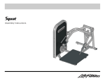
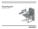
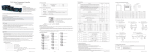
Seated Row
Assembly Instructions
Seated Row
Assembly Instructions
Item
Qty
Description
Part Number
Item
Qty
Description
Part Number
1
1
Pulley
3237801
22
1
Output Cam
7998501
2
2
Pulley Guard
79794XX
23
1
Output Plate
7998495
3
4
1
Tower Support
9
M10 x 45mm Bolt
80385XX
24
1
Output Ring
7998895
3251706
25
1
Rear Shroud
8024807
5
41
3/8” Flat Washer
3102514
26
1
Front Shroud
8024707
6
1
Bottom Brace
80004XX
27
4
M10 x 20mm Bolt
3251701
7
1
Center Frame
80187XX
28
1
Plate
7322301
8
1
Tower
79854XX
29
1
Seat Pad
74689XX
9
4
M10 x 130mm Bolt
3251720
30
2
M10 x 35mm Bolt
3251704
10
13
M10 Nylock Nut
3242002
31
1
M10 Hex Jam Nut
3236901
11
1
Seat Frame
80188XX
32
1
Cable
7999601
12
6
M10 x 90mm Bolt
3251715
33
1
Rod End Bearing
3237901
13
2
M10 x 70mm Bolt
3251711
34
1
M10 x 40mm Bolt
3251705
14
1
Right Handle
80191XX
35
1
Spacer
7489402
15
1
Workarm
80189XX
36
1
Cable Retaining Plate
8001801
16
1
Left Handle
80190XX
37
2
M8 Hex Jam Nut
3247502
17
1
Long Spacer
7330008
38
1
Output Cam Cover Plate
7998995
18
1
Pivot Shaft
7316506
39
4
Leveling Shim
7893101
19
2
Bearing
3235601
40
3
7/16” Hole Plug
3237401
20
2
Short Spacer
7330001
41
6
1” Hole Plug
3237403
21
3
M10 x 25mm Bolt
3251702
42
1
Multi-language Label
8047101
Tools Required:
O
O
O
O
O
17mm Wrench
Metric Allen Wrench Set
Ratchet with 17mm Socket
Rubber Mallet
Ratchet Extension
Seated Row
Assembly Instructions
1. Assemble the PULLEY (1) and two PULLEY GUARDS (2) to the TOWER
SUPPORT (3) using one M10 X 45mm BOLTS (4) and one 3/8" SAE
WASHER (5) as shown. Tighten the BOLT securely.
2. LOOSELY assemble the BOTTOM BRACE (6) and CENTER FRAME (7) to
the TOWER (8) using four M10 X 130mm BOLTS (9), eight 3/8" SAE
WASHERS (5) and four M10 NYLOCK NUTS (10) as shown.
3. LOOSELY assemble the SEAT FRAME (11) to the BOTTOM BRACE (6)
and CENTER FRAME (7) using four M10 X 90mm BOLTS (12), eight 3/8"
SAE WASHERS (5) and four M10 NYLOCK NUTS (10) as shown.
4. LOOSELY assemble the TOWER SUPPORT (3) to the CENTER FRAME (7)
and TOWER (8) using two M10 X 90mm BOLTS (12), four 3/8" SAE
WASHERS (5) and two M10 NYLOCK NUTS (10) at the CENTER FRAME
and two M10 X 70mm BOLTS (13), four 3/8" SAE WASHERS (5) and two
M10 NYLOCK NUTS (10) at the TOWER as shown.
5. Tighten all BOLTS and NUTS securely.
6. Install the RIGHT HANDLE (14) over the right end of the HANDLE SHAFT
of the WORKARM (15) as shown and secure it using one M10 x 45mm
BOLT (4). Repeat for the LEFT HANDLE (16).
7. Slide the LONG SPACER (17), PIVOT SHAFT (18), two BEARINGS (19)
and SHORT SPACERS (20) into the BEARING HOUSING (A) of the
WORKARM (15).
Insert the WORKARM between the mounting plates of the CENTER
FRAME (7) and secure it with two M10 X 25mm BOLTS (21) and two 3/8"
SAE WASHERS (5).
8. Assemble the OUTPUT CAM (22), OUTPUT PLATE (23), and OUTPUT
RING (24) using three M10 X 45mm BOLTS (4) and three 3/8" SAE
WASHERS (5) as shown. Tighten the BOLTS securely.
9. Assemble the REAR SHROUD (25) and FRONT SHROUD (26) to the
TOWER (8) using four M10 X 20mm BOLTS (27), four 3/8" SAE WASHERS (5) as shown. Be sure all tabs along the sides and top of the
SHROUDS are fully engaged in the slots located inside the TOWER.
Tighten the BOLTS securely. Do not overtighten the BOLTS.
10. Secure the OUTPUT CAM ASSEMBLY (B) to the TOWER HUB (C) using
one M10 X 25mm BOLTS (21), one 3/8" SAE WASHERS (5) and one
PLATE (28) as shown. Tighten the BOLT securely.
IMPORTANT: Be sure the OUTPUT CAM ASSEMBLY is oriented as
shown before securing it to the TOWER HUB.
Seated Row
Assembly Instructions
11. Attach the SEAT PAD (29) to the SEAT FRAME (11) using two M10 X
35mm BOLTS (30) and two 3/8" SAE WASHERS (5) as shown. Tighten
the BOLT securely.
NOTE: Some components have been removed from the illustration for
clarity.
12. Assemble one M10 HEX JAM NUT (31) onto one end of the CABLE (32)
approximately 1/2”. Assemble the ROD END BEARING (33) to the same
end of the CABLE until it meets the M10 HEX JAM NUT. Tighten the M10
HEX JAM NUT securely.
13. Loosely assemble the ROD END BEARING (33) of the CABLE (32) to the
WORKARM (15) using one M10 X 40mm BOLT (34), SPACER (35), 3/8"
SAE WASHER (5) and M10 NYLOCK NUT (10).
14. Route the CABLE (32) around the pulley of the TOWER SUPPORT (3) and
around the OUTPUT CAM ASSEMBLY (B). Insert the remaining end of
the CABLE through the inner hole of the OUTPUT CAM ASSEMBLY.
Insert the CABLE RETAINING PLATE (36) over the end of the CABLE.
Install two M8 HEX JAM NUTS (37) to the end of the CABLE.
Tighten the M8 HEX JAM NUTS until the WORKARM (15) begins to
move and all push pins still move in and out freely. Be sure the M8 HEX
JAM NUTS are tight against each other.
15. Attach the OUTPUT CAM COVER PLATE (38) to the OUTPUT CAM
ASSEMBLY (B) using three M10 X 45mm BOLTS (4) and three 3/8" SAE
WASHERS (5).
16. Place the unit in the intended place for use and check stability. If the unit
is not stable, the FEET (D) can be adjusted by inserting or removing supplied SHIMS (39).
To add or remove SHIMS, loosen the LEVELING FOOT BOLT (E) and
NUT (10) until the desired SHIM(S) can be inserted or removed. Lightly
tighten the BOLT and NUT. Do not over-tighten the BOLT and NUT.
17. Install HOLE PLUGS in all open bolt holes.
Seated Row
Assembly Instructions
2006 Life Fitness, a division of Brunswick Corporation. All rights reserved.
Life Fitness is a registered trademark of Brunswick Corporation.
©
TCRW
6.09.06
8060801 RevA-2