1
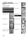
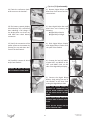
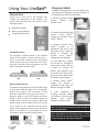
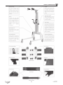
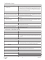
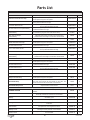
LiteGait® I 400E
LiteGait® I 500ES
Operator & Service Manual
LiteGait® I 360E / 400E / 400ES / 500E / 500ES
LiteGait® is a Registered Trademark of Mobility Research, Inc.
SERIAL
NUMBER
Serial Number of Your Device:
Note: Please keep your serial number in a safe and secure location. The serial number must be provided when seeking service for your LiteGait® device. The serial number provides us access to technical information regarding your device.
www.LiteGait.com
1-800-332-9255
IMPORTANT SAFETY INSTRUCTIONS
***WARNING***
READ ALL INSTRUCTIONS BEFORE USING LiteGait®
Maximum
Unit Height
Maximum
Patient Weight
LiteGait®
I 500E
8 Feet 10 Inches
500 lbs
LiteGait®
I 500ES
7 Feet 9 Inches
500 lbs
LiteGait®
I 400E
8 Feet 9 Inches
400 lbs
LiteGait®
I 400ES
7 Feet 8 Inches
400 lbs
LiteGait®
I 360E
7 Feet 8 Inches
360 lbs
Use only under the direct supervision of a health care professional or caregiver
Brakes should remain in the locked position at all times until
transfer from one location to another is initiated.
Operate on smooth and level surfaces ONLY.
www.LiteGait.com
1-800-332-9255
Dear LiteGait® User,
CONGRATULATIONS on your recent purchase of LiteGait®, the most innovative gait and balance
therapy training system available today. As you know, LiteGait® can be used with a wide variety of
patient impairment levels and conditions. If you have questions about the possible uses of LiteGait®
with particular patients, or are in need of some ideas for ways to use LiteGait® more effectively,
please do not hesitate to contact us for information relating to your individual situation. Our website also offers valuable information.
Like all quality therapy equipment, LiteGait® requires regular inspections. Enclosed is a check list for
your convenience. Please complete the checklist every 6 months to ensure the efficient, safe, and
effective operation of the LiteGait® unit. If you should find a problem with a LiteGait® part, please
contact the Technical Support Department immediately. Here are some resources, which will be of
help to you:
CLINICAL SUPPORT:
TECHNICAL SUPPORT:
WEBSITE:
USER FORUM :
[email protected]
[email protected]
www.LiteGait.com
www.LiteGait.org
Sincerely,
Customer Service Department
LiteGait®
LiteGait® is a Registered Trademark of Mobility Research, Inc.
PO Box 3141, Tempe AZ, USA 85280.
Table of Contents
Unpacking and Assembly .................................................................................. 10
Unit Diagram ..................................................................................................... 13
About Your Unit ................................................................................................. 13
USING Your LiteGait® ......................................................................................... 14
I. Control Unit ................................................................................................. 14
II. Charging LiteGait® ....................................................................................... 14
III How to Adjust Yoke Height .......................................................................... 15
IV. FlexAble ..................................................................................................... 15
V. Adjusting Handle Bars ................................................................................. 15
VI. Base and Casters ........................................................................................ 16
VIII. BiSym Scale Optional .............................................................................. 17
VII. Harness Application .................................................................................. 20
Training with LiteGait® ....................................................................................... 23
Unit Care and Maintenance .............................................................................. 25
Troubleshooting ................................................................................................ 28
Parts List ........................................................................................................... 30
Resource Directory ............................................................................................ 32
Limited Warranty Certificate .............................................................................. 33
9
www.LiteGait.com
1-800-332-9255
LiteGait® Assembly
5.) Loosen handle bar knobs and
raise handle bars.
Tools Required:
Scissors
1/2 inch socket or open-end wrench
5/16 inch Allen wrench (provided)
LiteGait® I Assembly Instructions:
Read below & follow pictures.
NOTE: Two people are required for safe assembly.
6.) Remove cardboard harness
and accessories box.
NOTE: Your LiteGait® may look different than the following images.
NOTE: If you have any questions during installation,
please contact Mobility Research Technical Support for
assistance.
1.) Inspect shipment and note
any visual damage to box and/or
crate
7.) Open cardboard harness and
accessories box.
2.) Remove screw located at the
bottom of crate
8.) Inspect contents of harness
and accessories box for damage.
3.) Lift off exterior box in order
to expose equipment
9.) Carefully cut all black plastic
straps securing base to pallet.
4.) Examine contents. Report
any damage to equipment
immediately
to
Mobility
Research Technical Support
10.) Using both people, remove
base from pallet.
CAUTION: DO NOT USE UTILITY
KNIFE TO OPEN BOX
10
www.LiteGait.com
1-800-332-9255
11.) Position base over pallet
with actuator near base as
pictured.
17.) Using two people lift
actuator up onto base. Orient
the actuator on base such that
the yoke and handle bars are
facing the same direction as the
legs of the base.
12) Cut and remove plastic wrap
from base compartment
18.) Route actuator cord
between base and actuator
plate before attaching actuator
to base. Cord should rest in slot
of back of actuator plate.
13.) Remove hand switch from
inside base compartment and
set aside for installation of
actuator
19.) Insert bolts and hand
tighten. Make sure while one
person is inserting bolts, the
other is holding the actuator.
Tighten the bolts until snug
using the Allen wrench.
CAUTION: DO NOT over tighten the
bolts.
14.) Prepare base for installation
of actuator. Remove four black
steel bolts from base using Allen
wrench in small box.
20.) Insert loose actuator cord
wires into compartment below
actuator plate.
15.) Remove screws securing
actuator to pallet.
21.) Position cover over actuator
cable and bolts securing
actuator plate to base. Cover is
secured using magnets.
16.) Lower handle bars on
actuator and tighten knobs
before lifting. Lift actuator from
pallet to base using two people
22) A slight gap may be present
between actuator and cover OR
base and cover.
11
www.LiteGait.com
1-800-332-9255
(Optional) BiSym Assembly
23.) Twist the red button clockwise to turn on the LiteGait®.
1.) Remove Digital BiSym card
board box from harness and accessories box
24) The battery capacity display
should display four solid black
bars indicating a full charge. If
the display does not show any
solid black bars check battery
connection.
2.) Open Digital BiSym Box card
board box and inventory the
following.
Digital BiSym Display
Digital BiSym Charger
25.) Verify the connection of the
power system to the actuator by
pressing the up and down buttons on the hand switch.
3.) Slide Digital BiSym Display
onto Digital BiSym bracket near
the yoke of the LiteGait.
26.) Carefully remove all shrink
wrap from LiteGait®.
4.) Connect the load cell cables
marked LEFT and RIGHT to the
LEFT and RIGHT Ports on the
side of the Digital BiSym Display
CAUTION: DO NOT USE UTILITY
KNIFE TO REMOVE SHRINK WRAP
5.) Connect the Digital BiSym
Battery Cord exiting the top of
the LiteGait® to the short cord
exiting the Digital BiSym Scale
NOTE: THE DIGITAL BISYM IS
CHARGED BY CONNECTING THE
DIGITAL BISYM CHARGING CABLE
TO THE DIGITAL BISYM BATTERY
CORD.
NOTE: DIGITAL BISYM SHOULD BE
CHARGED ONCE A MONTH OVERNIGHT
NOTE: DO NOT DISCARD DIGITAL
BISYM CHARGING CABLE
12
www.LiteGait.com
1-800-332-9255
LiteGait® Diagram
1
1. Yoke
2
2. Buckle Assembly
3
3. FlexAble
4
12
4. Handle Bar Assembly
13
5
5. Battery Compartment
11
6
6. Hand Switch
10
7
7. Total Locking Casters
9
8. Directional Locking Casters
9. Base/Frame
10. Control Unit
11. Actuator
12. Drop Down Yoke (OPTIONAL)
8
13. Digital BiSym Scale (OPTIONAL)
NOTE: Your LiteGait® may look different than image above
CONTROL UNIT: Junction box mounted in the base
for the battery power, handheld switch and contains
electrical safety protection circuitry. The battery pack
connects to this unit and is also located within a
compartment of the actuator.
HANDLEBARS: Unit has two adjustable handlebars.
The handle bars are attached to the unit using two
knobs.
About Your LiteGait®
LiteGait® is comprised of several parts.
YOKE: Y-shaped support that has four female buckles at the ends and is attached to the actuator with a
flat plate secured by four bolts.
OVERHEAD STRAPS: Four 44” long adjustable straps
with male connectors at one end and padded female
buckles at the opposite end. The male connectors
attach to the yoke buckles and the female buckles
attach to the harness providing postural support for
the patient.
HARNESS/GROIN PIECE: Adjustable wrap with a
buckle closure in the front and three adjustable
straps on each side. The four male connectors at the
top of the harness that attach into the female buckles of the overhead straps. The four female buckles
at the bottom of the harness allow for the connection of the groin piece. The H-shaped stitching on
the groin piece denotes the top (or body side) of the
piece.
ACTUATOR: The mechanism that raises and lowers
the yoke. The actuator consists of a concentric expanding and retracting square tower that houses the
DC motors, gearing and the screw mechanism. It
also provides the structural base to which the adjustable handlebars are attached.
NOTE: Over tightening the knobs may cause damage.
BASE: Two horizontal bars connected by two Ushaped tubes. The base moves freely over ground or
can be locked into place during use over a treadmill.
However the unit must be locked into place at all
other times.
CASTERS: Four casters are attached to the base. The
two casters on the left side are total locking and the
two casters on the right are directional locking. Be
certain to lock both caster brakes when using the
unit over a treadmill or when connecting the patient
to the unit.
WARNING: NEVER leave patient unattended in the unit.
BISYM (Optional): Provides a display of the pounds/
kilograms of support provided by each arm of the
yoke. The load cells that are installed in the yoke
sense the load on the yoke and feed it to the BiSym
Scale for processing and display.
13
www.LiteGait.com
1-800-332-9255
Using Your LiteGait®
Charging LiteGait
LiteGait® is equipped with a 24 volt battery pack
that needs to be charged on a weekly schedule. To
recharge battery follow the steps below.
Control Unit
Control Unit is the part of the LiteGait® that
controls the adjustment of the actuator. The
control STOP and Plug Icons box consists of the
following features.
1. Disconnect LiteGait® Smart
PowerTM
Battery
from
LiteGait® Base
Red ON/OFF Button
Battery Charge Indicator
2. Connect standard plug from
LiteGait® Smart PowerTM
Charger into LiteGait® Smart
PowerTM Battery
Emergency Down Button
3. Connect LiteGait® Smart
PowerTM Charger to an
appropriate 110 volt or 220
volt power outlet. While the
battery is charging, the
LiteGait® Smart PowerTM
Charger LED should be RED.
Red ON/OFF Button
The emergency ON/OFF Button is the ON/OFF
switch for the LiteGait. To turn the device on, rotate the red button clockwise and it should pop
outward. To turn the device off press the red button down. The device also automatically turns off
when connected to a power outlet
ON
4. Leave battery on charger
for 6-8 hours or overnight at
least once per week. The time
it takes to recharge the
battery pack depends upon
the health of the battery pack
and how low the battery pack
was before charging began.
OFF
5. LiteGait® Smart PowerTM
Charger will indicate a
completed charge when the
RED LED changes to GREEN
Battery Charge Indicator
The Battery Charge Indicator shows the idle charge
on the battery while the device is on. The indicator
displays the charge in 25% increments. 4 solid
black bars indicates a full charge on the battery. A
plug icon appears in the 50% capacity bar when
charge is down to 25%. The LiteGait® should be
charged when the plug icon appears. When the
battery charge is 0% the display will show a STOP
and a Plug icon, this indicates that the device
needs to be charged as soon as possible. When the
device is turned OFF or is connected to an outlet
the display indicates the STOP and Plug Icons.
100% Charge
25% Charge
6. Upon Completion of
charging, reconnect battery
into LiteGait® and disconnect
LiteGait®
Smart
PowerTM
Charger from power outlet.
NOTE: LiteGait® Battery Should be charged overnight AT
LEAST ONCE PER WEEK.
NOTE: Digital BiSym Scale (OPTIONAL) utilizes a second
battery located at the top of the LiteGait ® that should be
charged overnight AT LEAST ONCE PER MONTH.MONTH
0% Charge
14
www.LiteGait.com
1-800-332-9255
Using Your LiteGait®
How to Adjust Yoke Height
FlexAble
The LiteGait® powered actuator column is raised
and lowered by a hand switch with two up and
two down arrows.
FlexAble allows for the rigid yoke to become position
flexible, with up to 5 inches of travel. Thus, you can
maintain the rigid yoke position or make it flexible
giving the patient the option to experience more of
their balance and weight bearing at their own
discretion.
Flexible Support
Loosen the star knob on the bottom of the FlexAble.
The amount of deflection can be varied by the
amount the knob is loosened
Rigid Support
Tighten the star knob completely on the bottom of
the FlexAble
Raising the Yoke
Verify that LiteGait® has clearance above the yoke.
Depress the button with the up arrow on the
hand switch. Release the button when the yoke is
at the desired height.
Lowering the Yoke
Verify that LiteGait® has clearance below the yoke.
Depress the button with the down arrow on the
hand switch. Release the button when the yoke
lowers to the desired height.
NOTE: With the FlexAble or flexible, the LiteGait®
yoke and harness still provide full support to the
LiteGait® User.
Adjusting Handle Bars
Raised
Raising and Lowering the Handle Bar
Loosen each knob in equal portions. The knobs
should only need to be turned once to free the
handle bars. Once the knobs are loosened slide the
handle bars to the desired height. Hand tighten both
knobs equally. The knobs should only need to be
tightened one rotation.
Lowered
Emergency Lowering of Yoke
If the down buttons fail to lower during normal use
due to a low battery. There is an auxiliary down
button that can be pressed to lower the device.
Using a pen tip or small screwdriver, press the
black emergency down button, this lowers one of
the two columns of the LiteGait® when pressed.
CAUTION: Using the Emergency Down Button may
damage battery for future use. Use only in case of
emergency.
15
www.LiteGait.com
1-800-332-9255
Using Your LiteGait®
Locking and Unlocking Casters
Adjusting Handle Bar Configuration
To adjust the configuration, perform the following
steps.
Press the button on the quick release handle bar pin
and pull outward.
Adjust handle bar insert to desired length and orientation.
Press the button on the quick release handle bar pin
and insert handle bar pin. The pin can be inserted
vertically and horizontally.
Press tab to lock
Locked Caster
Total Locking Casters
Total locking casters are indicated by a red BRAKE
sticker on the locking lever. To lock the total
locking casters, press the tab until the brake snaps
into place. The caster will lock the swivel of the
caster and rotation of the wheel. Locking all four
casters will make the device stationary.
NOTE: While locking the caster prevents rolling of the
unit, it DOES NOT prevent the unit from sliding on a
sloped, slippery floor. The unit should only be used on a
flat floor away from stairs or ramps. NEVER leave a
patient unattended in the unit.
WARNING: LiteGait® Handle Bars are designed to be used
as a balance aid while using the LiteGait. Excess loading
of the handle bars may damage handle bars. Avoid
Having patients lift their weigh using the handle bars.
Directional Locking Casters
Directional lock casters are indicated by a green
STEER sticker in the locking lever. To lock the
directional locking casters, press the tab and align
the caster with the frame. Once Aligned this locks
the swivel of the casters and is beneficial for
walking in a straight path or placing LiteGait® over
a treadmill. Once the unit is positioned over a
treadmill, all four caster brakes need to be locked
Directional Locking Casters with Treadmill
Position LiteGait® near the treadmill (or where
you wish the patient to begin walking).
Base and Casters
Roll LiteGait® towards the front of the
treadmill, until the casters line up parallel to
the treadmill (or parallel to the path the
patient will follow—a hallway for example).
LiteGait® is equipped with four casters. There are
two total locking casters and two directional lock
casters. Each leg has one type of casters, the total
locking are mounted on the left leg the directional
locking are mounted on the right leg.
Press the directional locks to lock swivel of
casters
LiteGait® can now be easily rolled back and forth
over the treadmill or on a straight path in the
therapy room or hallway.
Total Lock
Directional Lock
16
www.LiteGait.com
1-800-332-9255
Using Your LiteGait®
BiSym Scale (Optional)
BiSym is a unique option available with LiteGait® to measure unilateral or bilateral support. LiteGait®’s
special design includes a two-armed yoke which holds the patient above each shoulder. From these two
points, the harness system can be adjusted to provide as much or as little support required to each side of
the body. The range of support can vary on each side from full to no support.
BiSym measures this asymmetric support at any given time during the gait cycle. Each arm of the yoke is
instrumented with a load cell with electrical connections to a box at the base of the yoke. This electronic box
powers the load cells, processes the signals and displays the supported loads of each arm or total support on
a display unit. This can be used for charting of therapy progression as well as accommodation of weight
bearing status.
Optionally, digital outputs representing the supported loads on both sides of the body are provided for digital
recording on to a PC.
These signals vary as the weight bearing load changes from the right to left side during the gait cycle. This can
be used as biofeedback for the patient. The more weight bearing by the patient = better posture = less work
by machine = smaller BiSym reading.
Connecting the BiSym
Connect Corresponding Load Cell wires from BiSym ready
LiteGait® yoke into BiSym Scale.
Slide BiSym Scale onto the pre-installed bracket at the base of
the yoke.
NOTE: Proper installation will leave the monitor visible to the patient
supported in the LiteGait®
Using the BiSym Scale
Press any button to turn the BiSym Scale on.
The BiSym Scale has an AUTO SHUT-OFF that can be adjusting during the CHANGE SETTING? mode (see
below)
Changing Display Modes
Press set to cycle through mode displays.
Right Support
Left Support
Difference (Right - Left)
Total (Right + Left)
Both Supports
The top row displays the supported load in pounds (lb) or Kilogram (kg) depending on the setting. The
bottom row displays a bar graph representing the value in the top row as a percentage of the specified
weight (default value 100lb).
Right Support
Left Support
Total (Right + Left)
Both Supports
17
Difference (Right - Left)
www.LiteGait.com
1-800-332-9255
Using Your LiteGait®
Changing BiSym Settings
To enter settings mode
Press and hold the SET button for 3 seconds or until display shows CHANGE
SETTING?
Press Set a second time to confirm change settings
After selecting the CHANGE SETTING? mode the BiSym will cycle through three screens
Weight Unit Setting
Auto Shut-Off Setting
User/Patient Weight Setting
Selecting the units measurement for weight reading on the scale
After selecting the CHANGE SETTING? mode, the Weight Unit Setting screen
will be displayed for three seconds.
Press the set button to toggle between pounds (lb) and kilograms (kg).
Adjusting the Auto Shut-Off time
After the Weight Unit Setting screen, the Auto Shut-Off Setting Screen will be
displayed.
Press the CAL button while on the Auto Shut-Off setting screen to adjust the
Auto Shut-Off. The Auto Shut-Off should be set between 3 and 60 minutes
WARNING: SETTING THE AUTO SHUT-OFF TO 0 WILL DISABLE THE AUTO SHUT-OFF. THIS WILL DISABLE
AUTO OFF FUNCTION ON THE BISYM SCALE RESULTING IN NO SHUT OFF OF THE BATTERY.
Setting the User/Patient Weight
Press the Set button to add 10 pounds at a time to the pre-set value of 100. Set the
value to the patient weight within the nearest 10 pound and the graphic display
represents the percentage of the set weight being supported. The default setting to
100 reflects the actual weight of the patient.
Charging the BiSym Scale
The BiSym scale battery is charged by a charger separate from the LiteGait® device.
The BiSym battery should be charged for 6 - 8 hours or overnight once per month.
The BiSym is connected to the BiSym Battery cable located at the top of the LiteGait.
Disconnect the battery cable from the BiSym Scale.
Plug the male end of the charger cable into the female end of the battery cable. Plug
the charger into the appropriate 110 or 220 volt outlet.
18
www.LiteGait.com
1-800-332-9255
Using Your LiteGait®
Setting the BiSym Zero Calibration
The zero calibration should only be set while the harness is attached to the LiteGait. Please make sure to connect the harness to the overhead straps prior to setting the zero calibration. There should be no additional
weight attached to the harness. Zero Calibration should be performed WITHOUT a patient in the device.
Press the CAL button and hold for three seconds or until the monitor displays “ZERO
CALIB” Confirm by pressing the SET button
Set the Left Zero by pressing the Set Button
Set the Right Zero by pressing the Set Button
Test zero calibration by toggling through the weight readout screens. All screens
should be displaying a zero pound or kilogram readout.
19
www.LiteGait.com
1-800-332-9255
Using Your LiteGait®
Harness Application
The harness was designed to support a patient in an upright position, allowing for full hip extension. This
upright posture plays a critical role in the effectiveness of the gait therapy performed with partial weight
bearing.
Harness Components
The front of the harness wrap refers to the point at which the two ends of the harness meet. The harness can
be worn with the closure either in the front or in the back. There are four buckles on the top and bottom of
the harness wrap. The four top buckles extend beyond the harness from the top seam and attach to the
LiteGait® overhead straps. The bottom four buckles attach to the groin piece and do not extend past the
bottom seam of the harness.
Girth Adjustment
Overhead Straps
Front
Groin Pieces
Preparing Harness for Application
1. Pick the appropriate harness (based on patient’s girth) and groin piece (based on patient’s anteriorposterior diameter) for the patient.
2. Adjust the groin strap buckles so there is symmetry in the straps-- equal strap length available on both
ends of the padded groin piece and equal from side to side.
3. Attach the groin piece to the back of the harness.
NOTE: The side of the groin piece with the H‐outline stitching (most
padded) will go against the patient’s body.
Estimating the Starting Size
Half the Girth Test
1. Estimate the harness girth before placing on the patient by folding the
unbuckled harness in half so that the ends meet.
2. Hold the folded harness in front of the patients torso to estimate the width
from one side of the body to the other.
3. Tighten or loosen the three rows of side straps on each side of the harness to
estimated girth.
Symmetry Test
1. With the unbuckled harness folded in half, check the alignment of the top
buckles (the ones that attach to the overhead straps of LiteGait). The buckles
should line up / be adjacent to each other . If not adjacent , make small
adjustment to side straps as needed to regain symmetry. Each side strap should
be similarly lengthened to achieve symmetry.
20
www.LiteGait.com
1-800-332-9255
Using Your LiteGait®
Harness Application - While Standing
2
1. Wrap harness around patient with lowest side straps even with GREATER
TROCHANTER.
2. Connect buckles top to bottom.
3. Adjust side straps* to the patient from bottom to top, alternate sides and
tighten evenly. Be sure to maintain harness position at Greater
Trochanter.
* To Tighten, push slack of strap towards buckle, while pulling free end as
shown. Do not tighten top buckles over rib cage.
1
3
NOTE: A loose harness will ride up when overhead support is applied. This will
cause discomfort in the groin region. A snug harness with no slack will grab the
pelvic girdle and hold in place distributing weight evenly throughout harness
wrap.
Quick Check
2 fingers should NOT fit between strap and body.
Bulges of tissue may be present between girth adjustment straps if
adjusted appropriately.
Attaching Groin Pieces
FRONT
1. Route the groin piece between legs to front.
2. Connect both buckles - one on each side.
3. Tighten the groin strap snugly so there is NO slack.
To tighten, grab the groin strap or strap cover and:
i. Pull out toward adductor surface of leg.
ii. Pull up toward groin piece buckle.
iii. Use other hand to pull down on excess strap on free end, then
repeat on other leg.
iv. Tighten back straps in the same fashion to remove all slack.
Quick Check
Groin Piece should have NO Slack. Padding should be equal front
and back. Padding should cover most of the inner leg with little or
no exposed strap.
Pull on top buckles, if harness moves up torso, straps require
additional adjustment.
iii
ii
i
BACK
iv
NOTE: A LOOSE GROIN PIECE DOES NOT IMPART GREATER COMFORT TO THE PATIENT, BUT ALLOWS THE HARNESS TO SLIDE UP THE TRUNK, PUTTING UNWANTED LOAD/FORCE ON THE GROIN
AREA. TIGHTEN THE GROIN STRAP SO THAT NO SLACK REMAINS IN THE STRAPS. THIS ASSURES
THAT THE HARNESS WILL NOT RIDE UP ON THE PATIENT.
21
www.LiteGait.com
1-800-332-9255
Using Your LiteGait®
Harness Application – In Supine
1. Roll patient away from you.
2. Attach groin piece and place harness on patient with half of the harness
rolled and under patient. (Figure 1)
3. Hold harness in place with lowest strap at greater trochanter
4. Roll patient into supine.
5. Pull harness around.
6. Straighten harness. Reach behind patient to feel back buckle position. Check
for symmetry. (Figure 2)
7. Connect front buckles
8. Tighten all 6 side straps with leg straight. (Figure 3)
9. Connect the groin piece to the front buckles and tighten as in previous
section. (Figure 4)
10. Roll patient away from you
11. Tighten back straps of groin piece, removing all slack. (Figure 5)
Figure 1
Figure 2
Figure 3
Quick Check
Harness should be equally spaced from side to side
Figure 4
Figure 5
Leg Strap Application
1. Wrap Velcro thigh cuff portion below bulk of thigh and above knee so strap
does not interfere with knee function.
2. Strap should be perpendicular to ground and pointing up toward the hip on
the outside of leg.
3. Connect male buckles on leg straps into plastic groin piece female buckles.
4. Tighten all three straps keeping center strap perpendicular to the ground
and on the lateral surface of the leg. The bifurcation point on the strap
(where the strap splits into two) needs to be at the hip joint axis of rotation
to maintain symmetry.
5. Straps must be tightened completely, using a two-handed technique and
getting rid of all slack, to properly anchor the harness in place and properly
transfer the support to the thighs.
CAUTION: SITTING WHILE IN THE LEG STRAPS WILL DISPLACE THE HIP AXIS OF
LOCATION AWAY FROM AND OUT OF THE LEG STRAPS; REPOSITIONING OF THE
LEG STRAPS WILL BE NECESSARY.
22
www.LiteGait.com
1-800-332-9255
Training with LiteGait®
Connect the Harness to your LiteGait®
1. Lock all four casters to make the device stationary and adjust the yoke to the correct position, giving the
patient approximately 5 to 6 inches of head clearance.
2. Extend the overhead straps until they are long enough to reach the metal buckles on the harness. Attach
the four buckles that hang from the overhead straps to the appropriate buckles on the harness. Pull
(shorten) the back straps until there is no slack. Leave a few inches of slack in the front straps.
3. Once the patient is connected, unlock casters. With one hand on LiteGait, press up button on hand switch
to lift patient into a standing position. Roll LiteGait® forward slightly while lifting so patient ends up
directly under the yoke buckles. If desired, have patient hold handlebars during sit to stand. If necessary,
adjust height of the handlebars to suit the patient.
4. Re-adjust overhead straps to maximize postural support as necessary. To tighten (shorten) strap, gently lift
up on the connected section of the strap and pull down on the loose end of the strap simultaneously. To
lengthen strap, lift metal tab up and out and then pull down on strap. Repeat as necessary for all straps.
5. The unit can now be used for over ground therapy or to assist the patient in stepping up onto the
treadmill.
If Lifting is not Necessary
With higher level patients who don’t need assistance to achieve standing, the harness may be connected to
the LiteGait® with the patient standing on the floor or over the treadmill.
1. Lock all four casters to make the device stationary and adjust the yoke to the correct position, giving the
patient approximately 5 to 6 inches of head clearance.
2. Extend the overhead straps until they are long enough to reach the metal buckles on the harness. Attach
the four buckles that hang from the overhead straps to the appropriate buckles on the harness. Adjust all
straps to maximize postural support as necessary.
3. If handlebars are desired, adjust height of the handlebars to suit the patient.
4. The unit can now be used for over ground therapy or to assist the patient in stepping up onto the treadmill
if necessary.
Stepping up onto Treadmill
1. Position LiteGait® unit at the end of the treadmill walking surface (if not already there) and lock both
directional casters.
2. Standing beside the patient, slowly roll the unit forward toward the front of the treadmill while
simultaneously pressing the up button on the hand switch.
3. While continuing to press the up button, assist the patient with stepping up onto the treadmill as needed.
4. Once the patient is standing on the treadmill, quickly re-tighten the overhead straps if necessary to
increase the support provided by the unit, or use the lift mechanism to increase the overall support. In
some cases it may be necessary to tighten all four overhead straps in order to decrease the distance
between the patient’s head and the overhead support (to achieve the ideal 5 to 6 inches of head
clearance).
4. Roll the unit to the front of the treadmill and lock the caster brakes.
5. Double check to see that the unit is locked into place and that the patient is in the center of the treadmill
walking surface.
6. Adjust the handlebars to the appropriate height.
CONTINUED ON PG 24
23
www.LiteGait.com
1-800-332-9255
Using Your LiteGait®
Stepping up onto Treadmill (Continued)
7. To exit the unit, reverse the process. Keep directional casters locked until the LiteGait® is at the end of the
treadmill. It is helpful to ensure that the locking casters are nudged into an outward rolling position so they
do not get caught on the treadmill as they roll.
8. Keep in mind that some patients will need to sit directly into a chair at the end of their session even if they
started the session in standing.
Over Ground Therapy
Follow “Connect the Harness to your LiteGait® and Lift Patient” steps as noted in previous section. LiteGait® can be
used over ground to perform gait training as well as to provide support for a variety of other activities such as balance
training, therapeutic exercise, postural support for ADL, etc. Please refer to your booklet “Protocols for Partial Weight
Bearing Gait and Balance Therapy” for more information, or email our clinical support department at
[email protected].
NOTE: THE CASTER BRAKES SHOULD BE LOCKED WHENEVER THE UNIT IS STATIONARY. RELEASE THE CASTER
BRAKES ONLY FOR MOVEMENT OF THE UNIT.
Over Treadmill
Over Ground
Unit Care and Maintenance
LiteGait® Maintenance
Your LiteGait® has been specially designed to be durable and relatively maintenance free. The frame is constructed from high strength steel, and has been painted with a special powder coat to resist rust and scratches.
Cleaning Frame:
Frequency
* FOLLOW STANDARD FACILITY INFECTION CONTROL PROCEDURES.
Cleaning Agent
DILUTED WINDEX TYPE CLEANING SOLUTION
Drying Method
WIPE DRY WITH CLEAN CLOTH
Special Cleaning
WD-40 CAN BE USED TO REMOVE DIRT OR OILY SPOTS.
Harness Maintenance
All harnesses and groin straps, including the iHarness, can be washed in hot water up to 80°C according to
facility infection control guidelines. Harnesses should be dried with low or no heat tumble dry. The iHarness
and the overhead LG straps can also be wiped with disinfection wash, per facility infection control
procedures. Use of bleach is discouraged and may effect the permeability of the harness material.
iHarness
& iGroin Pieces
Overhead Straps
Frequency
Facility infection control guidelines
Cleaning Agent
Facility infection control guidelines
Water Temperature
WASH IN UP TO 176°F (80°C)*
Drying Method
HARNESSES SHOULD BE DRIED WITH LOW OR NO HEAT TUMBLE DRY
Special Cleaning
WIPED WITH DISINFECTION WASH, PER FACILITY INFECTION CONTROL PROCEDURES
* Water temperatures between 104°F and 176°F may cause wrinkling of the iHarness material.
Harness Storage
The harness has been made of an durable fabric to retain its shape and effectiveness through many uses and
washings. However, it is imperative that the harness be stored properly to prevent damage to the buckles.
When not in use, store the harness in a place or area that will prevent the harness from being stepped on or
rolled over. The crushing downward force of a wheel chair or cart rolling over the harness would damage the
buckles, making the harness ineffective and unsafe for further use.
25
www.LiteGait.com
1-800-332-9255
Unit Care and Maintenance
To maintain the highest quality of function and safety, it is extremely important that you conduct regular maintenance checks of your LiteGait® unit and all of its parts. Please refer to the following checklist for an inspection guideline. If you should have any questions concerning the functional status of any of the LiteGait® parts,
please contact the Technical Support department immediately at [email protected]. It is recommended that you inspect the LiteGait® unit and all of its parts every 6 months.
Please rate the function of each item as follows:
1 = POOR 2 = FAIR 3 = GOOD 4 = EXCELLENT.
A rating of FAIR (2) or POOR (1) indicates that that part should be immediately replaced to maintain the safe
and effective use of the equipment.
Check All Components
Functionality
Cracks or Tears
Exposed or Frayed Wires
Loose/Rusted Bolts
Discoloration/Degradation
Check List
Recommended Replacement Schedule
Battery
24-30 Months
Charger
*
Hand Switch
*
Harness Wrap
18-24 Months
Groin Pieces
18-24 Months
Overhead Straps
*
Casters
*
Knobs / Pins
*
Grips / Covers / Caps
*
Buckles
*
Base
*
Actuator
*
*Replace As Needed Based on Condition
Please Send Copy of Completed Form Every 6 Months to Mobility Research Technical Support
Fax: 480-829-0737
Mail: Mobility Research — Technical Support
P.O. Box 3141
Tempe, AZ 85280
Email: [email protected]
Website: http://litegait.com/techsupport.html
Maintenance Contact Information
Facility Name
City
State
First
Last
Title
Phone
Fax
Email
Model
Serial Number
26
www.LiteGait.com
1-800-332-9255
Unit Care and Maintenance
27
www.LiteGait.com
1-800-332-9255
Troubleshooting - Power System
Symptom: Actuator Does Not Raise or Lower
1. Possible Cause:
Low Battery Charge / Battery need to be
Replaced.
3. Possible Cause:
Loose Cable Connection
4. Possible Cause:
Other Power System Issue
Symptom: Battery Does Not Charge
1. Possible Cause:
Device is Not Connected to Power Outlet
Resolution:
Charge the battery following the appropriate charging instructions until full
charge. If charging does not resolve issue contact Technical Support for replacement battery information.
Resolution:
Disconnect cables from Control Box. Firmly reconnect cables ensuring a secured connection
Resolution:
Contact Technical Support for further troubleshooting.
Resolution:
Connect charge cable to appropriate 110V outlet. (220V for International
Customers when applicable).
2. Possible Cause:
Charging Cord is Not Connected Properly
Resolution:
If the green LED indicates the charger is connected to a power outlet. Once
the charger is connected the green LED turns red. Once the battery is fully
charged, the LED turns back to green.
3. Possible Cause:
Power Outlet is Faulty
Resolution:
Check Outlet with another electrical device to ensure proper function of outlet.
Resolution:
If battery is not charged for an extended period the voltage may be too low
to charge. Contact Technical Support for replacement battery information.
Resolution:
Contact Technical Support for replacement battery information
4. Possible Cause:
Battery not been charged for an extended
period.
5. Possible Cause:
Battery has been in service for 30 months or
more.
6. Possible Cause:
Other Power System Issue
Symptom: Battery Does Not Hold Charge
1. Possible Cause:
Low Battery Charge
Resolution:
Contact Technical Support for further troubleshooting instruction.
2. Possible Cause:
Battery Needs to Be Replaced
Resolution:
Contract Technical Support for replacement battery information.
Resolution:
Charge the battery following the appropriate charging instructions until full
charge.
Troubleshooting - Casters
Symptom: Device Does Not Roll Easily
1. Possible Cause:
Resolution:
One or both of the Total Locking Casters are
Locked.
2. Possible Cause:
One or both Directional Locking Caster are
misaligned
The Total Locking Casters are labeled with a red BRAKE sticker. Unlock the
Total Locking Casters.
Resolution:
The Directional Locking Casters are labeled with a green STEER sticker and
engage when the caster is aligned with the leg of the base. If the LiteGait®
does not move forward and backward when the directional locking casters
are locked they are not aligned properly. Contact Technical Support for further repair instruction.
Resolution:
Contract Technical Support for repair information and.
3. Possible Cause:
One or more of the casters are loose and
are no longer secured to the frame or are
damaged
Symptom: Device Does Not Stay Stationary when Locked
1. Possible Cause:
Resolution:
One or more of the casters is not locked.
Make sure all four casters are locked to make the device stationary.
NOTE: If all casters are locked appropriately, contact Technical Support for further information.
28
www.LiteGait.com
1-800-332-9255
Troubleshooting - Harness
Symptom: Patient is complaining of groin or harness discomfort.
1. Possible Cause:
Resolution:
The harness wrap and/or the groin piece are
The harness and groin piece should be securely tightened from the start.* The
not tight enough.
harness wrap should be tight enough to grab on to the fatty tissue around the
abdomen. The groin piece should then be tightened securely to keep the
harness from riding up on the patient and creating unwanted pressure in the
groin area. A towel or a piece of foam can be wrapped around the patient’s
abdomen for added padding if needed.
Symptom: Harness is riding up on the patient causing pressure in the groin piece area
1. Possible Cause:
Resolution:
Groin piece has slack, harness rides up makThe bottom two straps on the harness wrap must be tightened securely, the
ing groin straps the only source of support
top one only if it rests below the rib cage. Applying the harness and groin
piece loosely will cause them to slide upward.*
Symptom: Frontal overhead straps are causing discomfort in the chest area of female patients.
1. Possible Cause:
Resolution:
The distance between the overhead straps
places load on breasts.
Use an extender to increase the front panel size and distance between the
overhead straps possibly avoiding the chest tissue. Conversely, the harness
wrap placed on the patient with opening in the back results in overhead
straps getting closer to each other in the front.
Symptom: The overhead straps slip off of patients shoulders
1. Possible Cause:
Resolution:
The overhead straps are too far apart.
Place the harness wrap with the opening in the back. This will bring the overhead straps closer to each other.
Symptom: The patient cannot stand to properly position and tighten the harness and groin piece.
1. Possible Cause:
Resolution:
Patient is too weak or unsafe to stand
Apply the harness in supine position. Avoid harness application in sitting as it
reinforces flexed hip position.
Troubleshooting - Digital BiSym (Optional)
Symptom: BiSym Display Is Not Powering On
1. Possible Cause:
Battery is Not Connected to BiSym Display
2. Possible Cause:
Low Battery Charge
3. Possible Cause:
Battery Needs to be Replaced
Symptom: BiSym Display is Not Reading Weight
1. Possible Cause:
Load Cell Cables are Not Connected
Resolution:
Connect Battery cable to BiSym Display
Resolution:
The Digital BiSym is powered by a separate battery located near the top of
the LiteGait®. Charge the BiSym Battery following the Digital BiSym charging
procedure.
Resolution:
Contact Technical Support for replacement battery information.
Resolution:
On the left side of the scale there should be three cables, two that look like
phone jack connectors and one that connects to the top of the LiteGait®.
Confirm that the cables are securely attached to the BiSym display.
NOTE: If load cells are connected properly and the BiSym continues not to read weight, contact Technical Support for further
information.
Symptom: BiSym Display is Not Reading Zero When No Weight is on LiteGait.
1. Possible Cause:
Resolution:
Harness is Moving Slightly
Any movement in the harness may cause some noise in the BiSym Scale
reading. A reading near zero is a normal occurrence.
2. Possible Cause:
Resolution:
BiSym scale requires Zero Calibration
Refer to Zero Calibration Instructions from BiSym section of manual.
Symptom: BiSym Does Not Automatically Power Down.
1. Possible Cause:
Resolution:
Auto Shut OFF is set too long or set to ZERO
Refer to the Change Settings from BiSym section of manual.
2. Possible Cause:
Issue with BiSym
Resolution:
Contact Technical Support for further troubleshooting instruction.
29
www.LiteGait.com
1-800-332-9255
Parts List
LiteGait® I Parts List – Harness and Accessories
Standard Adult Harness
Harness Wrap w/Overhead straps, covers and groin pieces
HAIN
1
Standard Adult Harness Wrap
A rigid, washable cloth wrap used with attachments that
provide postural support to the patient
HAIN-A1013
1
10.5” Groin Piece for HA
10.5” Padded, adjustable piece which connects to the harness
and is positioned between the legs.
HAIN-GP10
1
13” Padded, adjustable piece which connects to the harness
and is positioned between the legs.
HAIN-GP13
1
9” Groin Piece for HA (OPTIONAL)
9” Padded, adjustable piece which connects to the harness and
is positioned between the legs.
HAIN-GP9
1
Harness Extender
(OPTIONAL)
7.5” extension to plug into front of the harness wrap.
PHAEX
1
HSCS
2
13” Groin Piece for HA
HA / HS Leg Straps
(OPTIONAL)
Adjustable piece which connects to the harness and is
positioned around the legs for small adult / Adult Harness
Small Adult Harness
Harness Wrap w/Overhead straps, covers and groin pieces
HSIN
1
Small Adult Harness Wrap
A rigid, washable cloth wrap used with attachments that
provide postural support to the patient
HSIN-A910
1
9” Groin Piece for HS
9” Padded, adjustable piece which connects to the harness and
is positioned between the legs.
HSIN-GP9
1
10.5” Groin Piece for HS
10.5” Padded, adjustable piece which connects to the harness
and is positioned between the legs.
HSIN-GP10
1
Adjustable piece which connects to the harness and is
positioned around the legs for small adult / Adult Harness
HSCS
2
HA / HS Leg Straps
(OPTIONAL)
Junior Harness
HJ
1
Junior Harness Wrap
A rigid, washable cloth wrap used with attachments that
provide postural support to the patient
HJIN-A68
1
6” Groin Piece for HJ
9” Padded, adjustable piece which connects to the harness and
is positioned between the legs.
HJIN-GP6
1
8” Groin Piece for HJ
10.5” Padded, adjustable piece which connects to the harness
and is positioned between the legs.
HJIN-GP8
1
Diaper Harness
Harness Wrap w/Overhead straps and covers
HDJ
1
Diaper Harness Wrap
A rigid, washable cloth wrap used with attachments that
provide postural support to the patient
HDJ-A
1
Overhead Strap
Seatbelt like straps with one male and one female connection.
The male end connects into the buckles on the yoke. The
female end connects into the buckles on the harness.
HA-B
4
Overhead Strap Cover
The soft, cushioned material covering the female buckles of the
straps that attach to the harness.
HA-C
4
The electrical system that controls the positioning of the
actuator.
PS50E
1
A split red and green color coded connection cord that
electrically connects the control box to the actuator.
PS50E-A
1
24V battery pack.
PSSLD-B
1
The electric junction box.
PS50E-C
1
Charger Cord
The AC adapter cord that plugs into a wall outlet and the
control box.
PSSLD-CH-A
1
Hand Switch
The switch connects to the control box. The buttons allow for
the adjustment of the height of the device.
PS50E-E
1
Battery Cover
Rectangular metal plate that covers batteries.
PS50E-G
1
Control cover
Rectangular metal plate, with a wedge removed, which covers
the Control Box.
PS50E-H
1
Harness Wrap w/Overhead straps, covers and groin pieces
LiteGait® I Parts List – Power System
POWER SYSTEM
Actuator Cord
Battery
Control Box
30
www.LiteGait.com
1-800-332-9255
Parts List
LiteGait® I Parts List – Base
Base ASSEMBLY COMPLETE
LOW 30” inner frame
B40G30L
STND 30” inner frame
STND 34” inner frame
B40G30
B40G34
Total Locking Casters
Directional Locking Caster
B40G30L
B40G30L-C
2
B40G30L-D
2
HB50E
1
HB50E-A
1
HB50E-B
1
HB50E-C
2
HB50E-D
2
HB50E-G
2
LOW 34” inner frame
B40G34L
PLFM 34” inner frame
B40G34
STND 31” inner frame (LG I 500E/ES ONLY)
B50G31
B50G34
STND 34” inner frame (LG I 500E/ES ONLY)
Base Cap
1
1
1
1
1
1
1
1
The 2 x 2 inch, black covers for the legs of the base.
Wheel with hardware that locks via a tab labeled with a red
BRAKE sticker.
Wheel with hardware that locks into one direction via a tab
labeled with a green STEER sticker.
LiteGait® I Parts List – Handle Bars
HANDLEBARS ASSEMBLY
COMPLETE
Complete handlebars include handlebar arms and metal frame.
Part of the handlebars that encompasses the circumference of
the actuator/post.
Flat plate that sits between the posterior knobs to fasten and
the handlebars base box.
Posterior knobs used to fasten plate to handlebars base box.
These are round and allow the handlebars to be securely
locked into the correct position on the actuator/post.
Black 5” covers for the handles of the handlebars base box.
Handle is connected to the handlebars base box and can be
positioned proximal or distal and locked into place with handle
pin. Does not include patient grip covers.
Handlebars Base Box
Handlebar Plate
Knobs
Handle Covers
Adjustable Handles
Patient Grip Covers
Black 6” covers for the adjustable handles..
HB50E-E
2
Handle Pin
Press Button Quick Release Pin used to reposition the
adjustable handles.
HB50E-F
2
Y50E
1
Y50EZ
1
Y50ED
1
Y50EDZ
1
Y40E-A
1
Y40E-B
2
Contact
Mobility Reserach
1
P50M
P50MS
P50MS-C
P50MS-D
1
A digital read out scale that displays the amount of load
reduction on the lower extremities.
PBSD
1
Digital BiSym Battery
12V Battery for Digital BiSym
PBSD-B
1
Digital BiSym Charger
12V DC adapter cord that plugs into a wall outlet and connects
to Digital BiSym Battery.
PBSDB-C
1
LiteGait® I Parts List – Yoke
FlexAble Yoke Assembly Complete Straight
FlexAble Yoke Assem. Complete BiSym Ready – Straight
FlexAble Yoke Assembly Complete
– Drop Downh
FlexAble Yoke - BiSym Ready
Assem. Complete - Drop Down
Buckle Assembly
The complete top Y-shaped portion of the unit with buckles
attached. Unit Includes, FlexAble, Straight Bracket and load
cells for BiSym Scale.
The complete top Y-shaped portion of the unit with buckles
attached. Unit Includes, FlexAble, Straight Bracket and load
cells for BiSym Scale.
The complete top Y-shaped portion of the unit with buckles
attached. Unit Includes, FlexAble, Drop Down Bracket and load
cells for BiSym Scale.
The complete top Y-shaped portion of the unit with buckles
attached. Unit Includes load cells for BiSym Scale
The 2 x 2 inch, black covers for the legs of the base.
Wheel with hardware that locks via a tab labeled with a red
BRAKE sticker.
Sits between the Yoke and the post attachment and is cylinder
shaped. Blank or Flexable
Socks
Cartridge
LiteGait® I Parts List – Actuator
ACTUATOR/POST(E Models)
ACTUATOR/POST(ES Models)
Bolts for Base
Bolts for Yoke
Battery operated lift mechanism with 1000mm stroke
Battery operated lift mechanism with 80mm stroke
3/8 in –16 Standard
11 mm Standard
1
4
4
LiteGait® I Parts List – Digital BiSym
Digital BiSym Scale
If you should have any questions or would like to place a part order, please contact:
Phone: Technical Support at 1-800-332-9255 ext. 7104 Email:[email protected]
31
www.LiteGait.com
1-800-332-9255
Resource Directory
PHONE:
1.800.332.WALK (9255)
Toll free in U.S. and Canada
FAX:
480.829.0737
WEBSITE:
www.LiteGait.com
www.LiteGait.org
EMAIL DIRECTORY:
[email protected]
[email protected]
[email protected]
[email protected]
Technical Support
Clinical Support
Education Department
Sales Department
POSTAL ADDRESS:
Mobility Research
P.O. Box 3141
Tempe, AZ 85280
LiteGait® is a Registered Trademark of Mobility Research, Inc.
PO Box 3141, Tempe AZ, USA 85280.
(2015US)
32
www.LiteGait.com
1-800-332-9255
Limited Warranty Certificate
The Mobility Research warranty covers applicable parts and labor for repair or replacement as listed below†:
• 3 years on frame components due to broken or damaged welds.
• 3 years on the lift mechanism actuator
• 1 year on harness stitching, buckles and casters.
• 1 year on all electronics* - control box, wiring, charger, etc.
• 3 months warranty on battery due to defect
Losses due to work stoppage, lost revenues, damages due to neglect or abuse ARE NOT covered by this warranty. Shipping and handling charges ARE NOT
covered by this warranty. Tampering or modification on any and all components by unauthorized personnel is discouraged and will void your warranty.
THIS WARRANTY AND REMEDIES SET FORTH ABOVE ARE EXCLUSIVE AND IN LIEU OF ALL OTHER WARRANTIES, REMEDIES AND CONDITIONS, WHETHER
ORAL OR WRITTEN, EXPRESS OR IMPLIED. MOBILITY RESEARCH SPECIFICALLY DISCLAIMS ANY AND ALL IMPLIED WARRANTIES, INCLUDING, WITHOUT
LIMITATION, WARRANTIES OF MERCHANTABILITY AND FITNESS FOR A PARTICULAR PURPOSE. IF MOBILITY RESEARCH INC. CANNOT LAWFULLY DISCLAIM
IMPLIED WARRANTIES UNDER THIS LIMITED WARRANTY, ALL SUCH WARRANTIES, INCLUDING WARRANTIES OF MERCHANTABILITY AND FITNESS FOR A
PARTICULAR PURPOSE ARE LIMITED IN DURATION TO THE DURATION OF THIS WARRANTY. NO MOBILITY RESEARCH RESELLER, AGENT, OR EMPLOYEE IS
AUTHORIZED TO MAKE ANY MODIFICATION, EXTENSION OR ADDITION TO THIS WARRANTY. MOBILITY RESEARCH IS NOT RESPONSIBLE FOR DIRECT,
SPECIAL, INCIDENTAL OR CONSEQUENTIAL DAMAGES RESULTING FROM ANY BREACH OF WARRANTY OR CONDITION OR UNDER ANY OTHER LEGAL
THEORY, INCLUDING BUT NOT LIMITED TO LOST PROFITS, DOWNTIME, GOODWILL, OR DAMAGE TO EQUIPMENT AND PROPERTY.
†
Warranty excludes damage due to normal wear and tear, tampering with any components, from misuse and abuse, caused by cleaning and acts of God.
Warranty does not cover losses due to work stoppage, lost revenue(s), and damages due to neglect. Warranty excludes GaitKeeper Treadmills. Shipping
and handling charges are not covered by this warranty.
*If present.
In order for us to provide the very best in customer support, please activate your warranty by providing the following
information. This information will allow us to notify you for product updates, recall information, clinical support, technical
support, maintenance information and to receive our E-Newsletter. You may visit our website at http://www.litegait.com/
warranty.html and submit this form or fill in the information below and mail or fax back. (Keep a copy for your records)
Model
Serial number
Date of purchase
Facility Name:
Dept. used in
Address
Phone
(
)
Fax
(
Clinical Contact Name
email
Maintenance Contact Name
email
)
Products, Education, and Rehabilitation Solutions
Mobility Research Inc., P. O. Box 3141, Tempe AZ 85280
Phone: 1-800-332-9255 / 480-829-1727 Fax: 480-829-0737
Email: [email protected]
33
www.LiteGait.com
1-800-332-9255