1
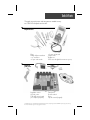
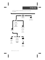
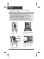
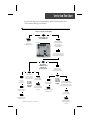
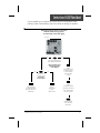
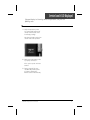
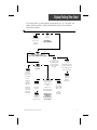
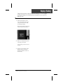
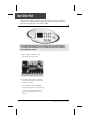
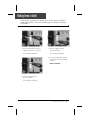
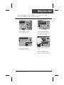
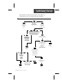
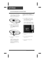
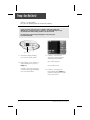
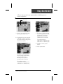
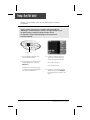
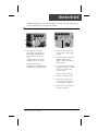
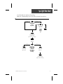
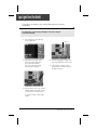
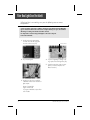
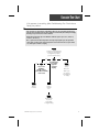
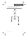
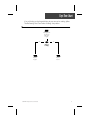
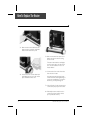
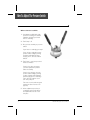
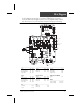
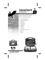
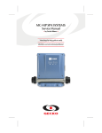
COAST SPAS
TSPA-MP SERVICE MANUAL
• Gecko Electronics Inc. •
Visual step-by-step guide to easily
identify & correct technical problems!
Table of Contents
Power & Ground Check
Electrical Wiring
GFCI
4
5
Programming
Low Level Programming
8
Error Conditions
Service Icon Appearing on Keypad Display
Service Icon and LED Displayed
Display is Flashing
Wrong Temperature Appearing on Keypad Display
Smart Winter Mode
9
13
17
20
23
Troubleshooting
Nothing Seems to Work!
Spa Does Not Heat!
Pump 1/Pump 2 Do Not Work!
Blower Does Not Work!
Light Does Not Work!
Fiber Box Light Does Not Work!
Ozonator Does Not Work!
Circulation Pump Does Not Work!
Keys Do Not Work!
TV Lifter Does Not Work!
TV Does Not Work!
VCR-DVD/CD-Radio Do Not Work!
25
29
33
39
43
45
47
49
51
53
55
57
How to ...
Replace The Board
Replace The Heater
Adjust The Pressure Switch
59
63
65
Miscellaneous
Wiring Diagram
Professional Repair Kit Info
67
68
Note: For spa repairs and troubleshooting with Pocket-tek technology please refer to Pocket-tek
User's Manual available from Gecko and at www.pocket-tek.com.
In an attempt to make this manual as useful as possible, it has been presented in two
formats. Problem-solving solutions are described with Troubleshooting Flow Charts
and also with Step-by-Step Procedures.
The two formats together should provide an overall complete explanation, with flow
charts providing an overview of specific problems, and step-by-step procedures giving
more detailed information.
Tools & Parts
The tools, test equipment and components needed to carry
out TSPA-MP metapack service calls.
Required tools:
Pliers
Phillips & flat screwdrivers
11/32" nut driver
1/4" open end wrench
3/8" open end wrench
Jumper cable
Multimeter
GFCI tester & digital thermometer (optional)
Required
pack parts:
Regulation sensor
Hi-Limit sensor
TSPA-MP system board
(or complete spa pack)
Transformer
Pressure switch
Fuses
Top side control (keypad)
Gecko Electronic Inc. sells Professionnal Repair Kits that include everything needed for TSPA-MP power spa pack servicing.
For more information, go to the last page of this manual.
Electrical Wiring
Correct wiring of the electrical service box, GFCI box and pack terminal
block is essential.
Electrical Box
GFCI
Pack Terminal Block
1• Carry out a visual inspection to check
for signs of miswiring.
Refer to supplied wiring diagrams.
Call an electrician if necessary.
4
TSPA-MP Metapacks Service Manual
GFCI Flow Chart
If GFCI trips, follow this Troubleshooting Flow Chart to identify
the problem:
yes
no
Is GFCI
properly
connected?
yes
Verify
Wiring Diagram
and reconnect it.
no
Unplug
everything,
including
heater and light
cord wires.
Is GFCI
still tripping?
Reconnect
one component
at a time
until GFCI
starts to trip.
Replace
transformer.
Replace
defective
component.
yes
There is
a problem
with the
cable.
Call an
electrician.
no
If GFCI is
still tripping,
disconnect
the incoming
power line.
Replace
GFCI.
Is GFCI still
tripping?
Replace
board
if GFCI is
still tripping.
TSPA-MP Metapacks Service Manual
5
GFCI Trips!
If all connections are made, but nothing seems to be working, you
probably have a power supply problem. Carry out the following tests to
identify and correct the problem:
Note that for new installations, GFCI trippings due to miswiring are common.
If breaker is wired properly, GFCI trippings may occur when total amount of current
drawn by spa exceeds breaker rating. This is highly unlikely as each spa pack output
is individually fused, and fuses will blow before GFCI trips.
A current leak to ground will also cause GFCI to trip. If any of the components is faulty
and a leak of more than 5mA occurs, the GFCI will trip to prevent electrocution.
There are different GFCI models on the market. Note that illustrations are examples only.
From electrical box
To spa
1• Verify if GFCI is properly
connected.
3• If GFCI is properly connected, but
still tripping, unplug all outputs including
heater and light cord wires.
Important
connections:
Neutral of GFCI
must be connected
to neutral bus.
Neutral from spa
must be connected
to breaker.
From electrical box
To spa
4• If GFCI still trips, replace transformer.
If it stops tripping, reconnect one
component at a time until GFCI
starts to trip. Replace defective
component.
2• If it is not, verify GFCI wiring
diagram and reconnect it.
6
TSPA-MP Metapacks Service Manual
GFCI Trips!
If GFCI continues to trip even after having replaced the transformer,
carry out the following tests to correct the problem:
1• Disconnect incoming power
lines.
If GFCI still trips, there must
be a cable problem.
Call an electrician!
2• If GFCI stops tripping.
Replace GFCI.
3• If GFCI trips again, replace
board. (Refer to "How to
Replace the Board" section
of this manual.)
TSPA-MP Metapacks Service Manual
7
Low Level Programming
Certain system operating parameters can be configured from the keypad. This
is normally done by Gecko or the spa installer, but may be done any time.
Low level programming:
To access low level programming, press and hold Program key for 20 seconds, after
which the first parameter code should appear on the display.
Use Up/Down keys to modify parameter values and Program key to change from
one parameter to the next. You must go through all parameters to exit this mode. If
you do not wish to change a parameter, simply press Program key to advance to the
next parameter.
List of parameter configurations
1- Pump 1
Display: P1 x
Value of x: 1 = single-speed
2 = two-speed
2- Pump 2
Display: P2 x
Value of x: 0 = not installed
1 = single-speed
2 = two-speed
3- Blower
Display: bL x
Value of x: 0 = not installed
1 = single-speed
2 = two-speed
3 = three-speed
4- Light
Display: LI x
Value of x: 0 = not installed
1 = 12 VAC (single-intensity)
2 = 12 VAC (triple-intensity)
3 = 120 VAC (auxiliary 1
relay )
4 = Internal fiber box control
mode (aux. 1 & 2 relays)
8
5- Ozone
Display: O3 x
Value of x: 0 = not installed
1 = on only in filter cycle
2 = always on
6- Circulation pump
Display: CP x
Value of x: 0 = not installed
1 = regulated (with spa
temperature)
2 = always on
7- Service message
Display: SEr x
Value of x: 0 = message not displayed
1 = message displayed every
8000 hours
8- Current limiting option
Display: Cu x
Value of x: 0 = low current (heater off
if more than one pump
is on at high speed)
1 = high current (no restrictions)
TSPA-MP Metapacks Service Manual
Service Icon Flow Chart
If service icon appears on keypad display, follow Troubleshooting Flow
Chart below to identify the problem:
Service icon appears on the display!
yes
no
Remove pack cover.
Is board LED on?
Follow
service icon
& LED flow chart.
Make sure low
level programming
for circ. pump
is set properly and
reset breaker.
LED indicator
Turn Pump 1on (or start
circ. pump if installed by
increasing the set point).
yes
no
Do you have
continuity on your
voltmeter for
pressure switch?
yes
Verify
pressure
switch
connection.
Short pressure
switch terminals
with a jumper cable.
no
Disconnect
pressure switch
for 5 seconds
and reconnect it.
Replace pressure
switch cable.
Is service
icon still
appearing
on keypad
display?
yes
Try to adjust
pressure switch.
Replace pressure
switch cable.
Replace pressure
switch if problem
persists.
no
Is service
icon still
appearing
Remove anything
on keypad
display? obstructing filter canister
or piping. Clear any air
locks. Verify water valves.
If problem persists,
replace board.
Try to adjust
pressure switch.
If problem persists,
replace board.
TSPA-MP Metapacks Service Manual
Replace pressure
switch if problem
persists.
9
Service Icon is Displayed!
The service icon indicates a pressure switch problem.
There must be enough water in the spa for normal operations. System may detect error
condition if spa filter is dirty or if something restricts flow of water in piping.
The heater will automatically shut down when error condition occurs.
Power may remain On when the following steps are carried out.
1• Verify if pump is working. If
pump is not working right,
refer to pump section of this
manual.
2• Make sure low level setting for
pressure switch is set correctly:
CP 0: circ. pump not installed
CP 1: circ. pump installed
3• If Pump 1 is working properly,
turn it on by pressing Pump 1
key (or start circ. pump by
increasing set point) and test
continuity on pressure switch.
5• If you do not detect continuity,
verify if pressure switch cable is
properly connected to pressure
switch and board.
4• If you detect continuity, go to
step #10.
10
TSPA-MP Metapacks Service Manual
Service Icon is Displayed!
6• Ensure adequate water flow in the
heater and short two pressure switch
terminals with jumper cable.
7• If service icon disappears, first
make sure there is no blockage of
water or air lock and check water
valve.
If the installation is older than 2 years,
replace the pressure switch and recalibrate it.
If installation is recent, try readjusting the pressure switch. If this is not
possible, replace switch.
(Refer to "How to Adjust the
Pressure Switch" section of this
manual.)
TSPA-MP Metapacks Service Manual
8• If service icon still appears, the
problem may be either with switch
cable or board.
Remove plastic cover and replace
cable.
9• Replace board if error condition still
persists. (Refer to "How to Replace
the Board" section.)
11
Service Icon is Displayed!
Power may remain On while the following steps are carried out.
10• If you have continuity on pressure
switch, follow these steps:
Disconnect pressure switch cable
for 5 seconds and reconnect it.
If error condition disappears, adjust pressure switch, if it is a new
installation (less than two years) or
replace it.
11• If error condition persists, remove
plastic cover and replace pressure
switch cable.
12• Replace board if error condition
still persists. (Refer to "How to
Replace the Board" section of this
manual.)
(Refer to "How to Adjust the
Pressure Switch" section of this
manual.)
12
TSPA-MP Metapacks Service Manual
Service Icon & LED Flow Chart
If error condition occurs (potential Hi-Limit sensor or temperature probe
problem), follow Troubleshooting Flow Chart below to identify the problem:
Turn breaker off then on again to reset the system.
If Hi-Limit condition no longer persists,
check for blockage of water in the piping.
LED indicator
yes
no
Take water temperature
with a digital thermometer.
Are you getting correct
water temp. reading
on the display?
yes
no
When error
condition occurs,
does heater
barrel feel hot?
Verify if anything
is obstructing water
flow (closed traps or
dirty filters).
If error
condition still
persists,
replace board.
Verify if
temperature probe
is touching water
or if cold air from
back can affect
reading.
Verify if
temperature probe
is properly connected.
If so, replace probe
and reset breaker.
Replace board if
error condition
still persists.
TSPA-MP Metapacks Service Manual
13
Service Icon & LED Displayed
The service icon and LED error condition is related to the Hi-Limit sensor or
temperature probe.
Turn breaker off then on again to reset the system.
If service icon and LED disappear, wait until they are displayed again on keypad.
Power may remain On.
1• Take water temperature with
digital thermometer.
2• If keypad display shows correct
temperature:
a- Check if heater barrel feels hot.
If it's hot, verify if anything is
obstructing the flow of water
(closed valves or dirty filter).
b- If heater barrel feels cold, replace board. (Refer to "How
to Replace Board" section of
present manual.)
3• Proceed to following page if
keypad display shows incorrect
temperature.
14
TSPA-MP Metapacks Service Manual
Service Icon & LED Displayed
If keypad display isn't showing correct temperature, carry out the
following tests:
1• Verify if temperature probe
is in contact with water and if
cold air from the back could
be affecting readings.
Use foam to isolate probe from
cold air if that is the problem.
2• Make sure temperature probe
is properly connected.
If it is, replace probe and reset
breaker.
3• Replace board if HL error
condition still persists. (Refer
to "How to Replace the
Board" section of this manual.)
TSPA-MP Metapacks Service Manual
15
16
TSPA-MP Metapacks Service Manual
Display Flashing Flow Chart
On certain packs, if system detects temperature at 112°F or higher, the
display will start flashing. Follow Troubleshooting Flow Chart below to
identify the problem:
yes
no
Press
any key.
A power failure
has occurred.
Has display
stopped flashing?
System
works fine.
yes
no
Are you getting correct
water temp. reading on the display?
yes
no
Is weather
very hot?
Verify if
temperature probe
is touching water
or if cold air from
back can affect
reading.
Verify if
temperature probe
is properly connected.
Remove
spa cover
(even during
the night).
Start
blower, if
spa is
equipped
with one.
Wait until
spa cools
down (add
cold water
if needed).
yes
Test element.
If opened,
replace it.
If element
works fine,
replace board.
TSPA-MP Metapacks Service Manual
Replace
board if
problem
still persists.
no
Lower set point
below actual
temperature of
water.
"Heater" icon
on keypad display
should disappear.
Do you get a
240 VAC reading
between
two heater wires
on the board?
If so, replace probe
and reset breaker.
Pump is
overheating
water during
filter cycle.
Lower
filter cycle
duration.
17
Display Is Flashing
If digital thermometer water temperature reading is 112°F or higher and
keypad display indicates correct temperature, carry out the following
tests:
If display stops flashing after pressing a key, this means that a power failure has occurred.
System works fine.
If weather is very hot:
1• Remove spa cover (even during
the night). Start blower if spa is
equipped with one. Wait until
spa cools down (add cold water
if necessary).
4• If you do not read 240 VAC, pump
may be overheating water during
filter cycle.
If hot weather is not a factor:
Enter Programming mode and
shorten filter cycle duration.
2• Lower set point below current
water temperature.
5• If you do read 240 VAC, test the
element. If it is opened, replace
it. If element works fine, replace
board. (Refer to "How to Replace
the Board" section of this manual.)
"Heater" icon should disappear
from keypad display.
3• Remove spa cover. With a voltmeter, read the voltage between
the two heater wires on the board.
18
TSPA-MP Metapacks Service Manual
Display is Flashing
If digital thermometer water temperature reading is 112°F or higher
and keypad display isn't showing correct temperature, carry out the
following tests:
1• Verify if temperature probe
is in contact with water and if
cold air from the back could
be affecting readings.
Use foam to isolate probe from
cold air if that is the problem.
2• Make sure temperature probe
is properly connected.
If it is, replace probe and reset
breaker.
3• Replace board if display is still
flashing. (Refer to "How to
Replace the Board" section of
this manual.)
TSPA-MP Metapacks Service Manual
19
20
TSPA-MP Metapacks Service Manual
Wrong Temperature Flow Chart
On certain packs, if system detects that temperature is not within normal
limits, a highly incorrect temperature will be displayed. Follow Troubleshooting Flow Chart below to identify the problem:
Check if regulation
probe is properly connected.
Unplug probe connector
and clean pins on the
board (even a small coating
of film may cause a bad
connection).
Reconnect the probe.
Replace probe with
a spare and verify if
problem is solved.
If it is, replace
probe with spare.
Replace board if
problem persists.
TSPA-MP Metapacks Service Manual
21
Wrong Temperature Displayed
Wrong temperature on keypad display indicates a problem with regulation
sensor. The system is constantly verifying if temperature probe reading is
within normal limits.
Note that water temperature must be over 35°F in order to carry out the following steps.
Power may remain On.
3• Reconnect probe.
If wrong temperature is still
displayed on keypad, replace
probe with a spare and place
probe head directly in spa
water.
1• Verify if regulation probe (sensor
located in spa) is properly connected.
If problem is solved, replace
probe.
4• Replace board if problem
persists.
2• Disconnect probe connector
and clean probe connector pins.
Even a small coating of film may
cause a bad connection.
22
TSPA-MP Metapacks Service Manual
Smart Winter Mode Chart
If pumps have started up on several occasions and "Filter Cycle" indicator
is flashing on keypad, follow this Troubleshooting Flow Chart to identify the
problem:
yes
no
Is the water temperature
of the spa lower than
the desired temperature?
yes
no
Do you
read 240 VAC
to the
heater?
Refer to
"Spa not heating"
section.
The system
is working
properly.
Smart Winter Mode
If pumps have started up several times and "Filter Cycle" icon is flashing,
the system has detected water cold enough to freeze the pipes and has
gone into the protective Smart Winter Mode.
An irregularly flashing "Filter Cycle" icon means that the system has stopped filtering after
3 hours because water temperature exceeds Set Point by more than 2˚F. If the temperature
cools down before the scheduled end of the cycle, filtering will resume for the remainder of
the programmed cycle duration.
1• With a digital thermometer, verify
the temperature of the water.
2• If the water temperature is lower than
the desired temperature, measure the
voltage to the heater.
If your reading is approx. ≈240 VAC,
Smart Winter Mode is working properly.
If you do not read ≈240 VAC, refer to
the "Spa not heating" section of this
manual.
24
TSPA-MP Metapacks Service Manual
"Nothing Seems to Work" Flow Chart
If nothing seems to work, follow the Troubleshooting Flow Chart below to
identify the problem:
yes
Verify if
keypad is
connected
correctly
to board.
All eight pins
must be plugged in
and black wire
must be on top
of the plug.
no
Do you get a
≈240 VAC reading
between
line 1 & line 2,
≈120 VAC
between
line 1 & neutral,
≈120 VAC
between
line 2 & neutral
on the board?
There is
an electrical
wiring
problem.
Call an
electrician.
Replace transformer
fuse if there is still nothing on
the keypad display.
If nothing still works,
clean the transformer
orange connector pins
(even a small coating of film may
cause a bad connection).
Replace transformer if
problem persists.
Replace board if
problem still persists.
TSPA-MP Metapacks Service Manual
25
Nothing Seems to Work!
If everything is connected, but nothing seems to work, there is probably a
power supply problem. Carry out the following tests to identify and correct
the problem:
1• On the terminal block, measure
voltage between line 1 and line 2.
You should get ≈240 VAC.
3• Measure voltage between
line 2 and neutral.
You should get ≈120 VAC.
4• If you do not get good readings,
this indicates an electrical wiring
problem.
Call an electrician!
2• Measure voltage between
line 1 and neutral.
You should get ≈120 VAC.
26
TSPA-MP Metapacks Service Manual
Nothing Seems to Work!
If you are getting good voltage readings, but nothing seems to work,
carry out the following tests to correct the problem:
1• Verify if keypad is correctly
connected to the board.
3• If nothing works, clean transformer orange connector pins.
Even a small coating of film may
cause a bad connection.
Xfo
fuse
2• Replace transformer fuse
if nothing still seems to work.
4• Replace transformer if problem
persists.
5• If problem is still not solved,
replace board. (Refer to "How
to Replace the Board" section.)
TSPA-MP Metapacks Service Manual
27
28
TSPA-MP Metapacks Service Manual
"Spa Not Heating" Flow Chart
If the spa does not seem to be heating the water, follow the
Troubleshooting Flow Chart below to identify the problem:
yes
no
Is service icon
appearing on
keypad display?
Refer to
"Service Icon
Displayed"
section.
yes
Ensure temp.
set point is
higher than
actual water temp.
no
Has "Heater" icon appeared on
keypad display? (If "Heater" icon is
flashing, system is in LC mode.
See Low Level Section.)
yes
no
Make sure system
Can you read
is not in Economy mode.
240 VAC between
two terminals
of the heater
yes
no
on the board?
Take water temperature
and compare with
temp. value displayed
on keypad.
Is difference
greater than ±2°F?
Replace
board.
yes
no
System
works fine.
Is temperature
probe touching water
or hot air rear
affecting reading?
Isolate back of
probe with foam.
Are
heater wires
connected
correctly
to the
element?
yes
no
Replace
temperature probe
with spare.
Try tightening wires
to the board & element.
Still not heating?
Replace
element.
TSPA-MP Metapacks Service Manual
Replace
board.
29
Spa Not Heating!
If the spa does not appear to be heating the water,
carry out the following tests to correct the problem:
1• Check if service icon is appearing
on keypad display. If it is, refer to
"Service Icon Appearing on Keypad
Display" section of this manual.
If "Heater" icon does not light up, make
sure system is not in an Economy mode
cycle.
4• Use a digital thermometer to take
water temperature and compare
your reading with the temperature
value on the keypad display.
If values are different (±2°F), verify if
sensor is touching water or if hot air
from rear could be affecting readings.
2• If service icon is not on keypad
display, try to increase temperature by raising temperature set
point. Press Up key to increase
set point.
"Set
Point"
icon
"Heater"
icon
3• Verify if "Heater" icon appears on
the display.
"Heater" icon will be on when
heater is on. It will flash if more
heat has been requested, but
heater has not yet started or if
system is in LC mode (see Low
Level Section).
30
5• If yes, use foam to isolate behind
the probe.
6• If no, replace temperature sensor
with a spare one.
7• If spa is still not heating, replace
the board.
TSPA-MP Metapacks Service Manual
Spa Not Heating!
If "Heater" icon appears on the display, but spa is still not heating, carry
out the following tests to correct the problem:
If "Heater" icon lights up on the display:
1• Remove plastic cover and measure
voltage between two heater screws
on the board.
Replace board if you are not
getting a reading of ≈240 VAC.
1-Kw heater: P21 & P56
4-Kw heater: P63 & P44
TSPA-MP Metapacks Service Manual
2• If voltage reading is correct, verify
if heater wires are properly connected to the element.
If not, tighten wires to board and
element.
3• If problem persists, replace the
element.
31
32
TSPA-MP Metapacks Service Manual
Pump Flow Chart
If Pump 1 or Pump 2 is not working, follow Troubleshooting Flow Chart
below to identify the problem:
yes
no
Is display
flashing?
Refer to
specific section.
yes
no
Does Pump 1
or Pump 2 icon
appear on
keypad display
when you
press Pump 1 or
Pump 2 key?
Verify if low level
programming is set correctly
(See Low Level Section).
Replace keypad.
yes
no
If still not working,
replace board.
Do pumps work
in either speed?
Verify
low level
programming.
yes
no
Replace Pump 1 or
Pump 2 fuse.
Pump(s) still not working!
yes
no
Measure voltage
on the board for both speeds.
Replace Pump 1
or Pump 2.
Do you get 240 VAC
reading for
both speeds?
TSPA-MP Metapacks Service Manual
Replace
board.
33
Pump 1 Does Not Work!
If Pump 1 is not working,
carry out the following tests to correct the problem:
To increase the life of the relay, we use a "snubber" circuit on the pump relay.
With this type of circuit, if no pump is connected to an output and relays are open,
the voltmeter will continue reading around 60 volts. This is normal.
It is important to measure voltage when pump is connected to pack.
Power must remain On.
"Pump 1" icon
1• Check if the display is flashing.
If yes, refer to specific section.
2• Verify if "Pump 1" icon appears on
keypad display when you press
Pump 1 key.
If "Pump 1" icon does not appear,
check low level programming first
(see Low Level Section).
34
3• If "Pump 1" icon does not
appear, use a spare keypad to
verify if keypad is defective.
If it is, replace keypad.
If not, replace board.
4• If "Pump 1" icon appears on
keypad display when Pump 1 key
is pressed, verify if Pump 1 works
in any of the speeds.
TSPA-MP Metapacks Service Manual
Pump 1 Does Not Work!
If Pump1 does not work in any speed, perform the following tests to
correct the problem:
Pump 1 fuse
1• If Pump 1 does not work in either
speed, replace Pump 1 fuse.
2• If replacing the fuse does not work,
or if Pump 1 works in one of two
speeds, take voltage reading on the
board for both speeds.
3• Turn Pump 1 to high speed and
measure voltage between white
and black wire connectors:
240 VAC pump: P64 & P57
120 VAC pump: P64 & P48
The reading shoud be:
≈240 VAC for a 240 VAC pump
≈120 VAC for a 120 VAC pump
4• If voltage is correct, replace
Pump 1.
5• If not, replace board.
Turn Pump 1 to low speed and
measure voltage between white
and red wire connectors:
240 VAC pump: P37 & P57
120 VAC pump: P37 & P48
The reading shoud be:
≈240 VAC for a 240 VAC pump
≈120 VAC for a 120 VAC pump
TSPA-MP Metapacks Service Manual
35
Pump 2 Does Not Work!
If Pump 2 is not working, carry out the following tests to correct
the problem:
To increase the life of the relay, we use a "snubber" circuit on the pump relay.
With this type of circuit, if no pump is connected to an output and relays are open,
the voltmeter will get a reading of around 60 volts. This is normal.
It is important to measure voltage when pump is connected to the pack.
Power must remain On.
"Pump 2" icon
1• Check if display is flashing. If it is,
refer to specific section.
2• Verify if "Pump 2" icon appears on
keypad display when you press
Pump 2 key.
If "Pump 2" icon does not appear,
check low level programming first
(see Low Level Section).
36
3• If "Pump 2" indicator does not
appear, use a spare keypad to
verify if spa keypad is defective.
If it is, replace keypad.
If not, replace board.
4• If "Pump 2" icon appears on the
display when you press Pump 2
key, verify if Pump 2 works in any
speed.
TSPA-MP Metapacks Service Manual
Pump 2 Does Not Work!
If Pump 2 is not working in any speed, carry out the following tests to
correct the problem:
Pump 2 fuse
1• If Pump 2 does not work in either
speed, replace Pump 2 fuse.
2• If replacing fuse does not correct
problem, or if Pump 2 works in one
of two speeds, read voltage on the
board for both speeds.
3• Turn Pump 2 to high speed and
measure voltage between white
and black wire connectors:
240 VAC pump: P35 & P58
120 VAC pump: P35 & P45
The reading shoud be:
≈240 VAC for a 240 VAC pump
≈120 VAC for a 120 VAC pump
4• If voltage is correct, replace
Pump 2.
5• If not, replace board.
Turn pump 2 to low speed and
measure voltage between white
and red wire connectors:
240 VAC pump: P22 & P58
120 VAC pump: P22 & P45
The reading shoud be:
≈240 VAC for a 240 VAC pump
≈120 VAC for a120 VAC pump
TSPA-MP Metapacks Service Manual
37
38
TSPA-MP Metapacks Service Manual
Blower Flow Chart
If blower isn't working, follow this Troubleshooting Flow Chart to identify the
source of the problem:
yes
no
Does "Blower"
icon appear
on keyboard display
when you press
Blower key?
yes
no
Do you
read
≈120 VAC for
120 VAC blower
(or ≈240 VAC for 240 VAC)
at blower
output on
the board
(in high speed)?
yes
It's possible
that blower
is not getting
enough air entry.
Verify blower
low level
programming
(see Low Level Section).
Replace
keypad.
Replace
board.
no
Does
blower restart
after a few minutes
(to cool down
after being
shut off)?
Replace
blower.
Replace
blower
fuse.
Create an opening
to allow more air
under spa skirt.
Replace board
if blower
still does
not start.
TSPA-MP Metapacks Service Manual
39
Blower Does Not Work!
If blower is not working,
carry out the following tests to correct problem:
To increase the life of the relay, a "snubber" circuit is used on the blower relay.
With this type of circuit, if no blower is connected to an output and relays are open,
the voltmeter will continue to get a voltage reading of around 60 volts. This is normal.
It is important to measure voltage when the blower is connected to the pack.
Power must remain On.
1• Verify if "Blower" icon lights
up on keypad display when
you press Blower key (icon
will flash when blower is in
low speed).
2• Verify if blower low level
programming is set correctly.
3• If "Blower" icon does not appear on keypad display, then
replace keypad.
4• If "Blower" icon still does not
appear on keypad display, then
replace the board.
40
TSPA-MP Metapacks Service Manual
Blower Does Not Work!
If "Blower" icon lights up on control display, but blower still isn't working, carry
out the following tests to correct the problem:
Blower fuse
1• If icon lights up on keypad
while blower is in high speed,
take voltage reading between
white and black wire connectors:
120 VAC blower: P49 & P43
240 VAC blower: P59 & P43
Your reading should be:
≈120 VAC for a 120 VAC blower
≈240 VAC for a 240 VAC blower
2• Replace blower fuse if you do
not get a high enough voltage
reading.
3• Replace board if you still aren't
getting a voltage reading.
(Refer to "How to Replace the
Board" section.)
4• If you don't get a good voltage
reading, check if you can restart
blower a few minutes after
being turned off.
Replace blower if it does not
start after cool down period.
5• If blower does start up after
cool down, it's possible that it
is not drawing in enough air.
6• Enlarge the opening to allow
more air into blower.
TSPA-MP Metapacks Service Manual
41
42
TSPA-MP Metapacks Service Manual
Spa Light Flow Chart
If spa light does not appear to be working,
follow the Troubleshooting Flow Chart below to identify the problem:
no
yes
Have you
tried replacing
the spa
light bulb?
yes
no
Try replacing
light bulb.
Is light
still not
lighting
up?
Verify low level
programming
(see Low Level Section).
Try new
keypad.
yes
Replace spa
light socket.
no
Do you get a
12 VAC reading
on light ouput
on board
when light is
on at highest
intensity?
Replace spa
light fuse.
Replace board if
light is still not working.
TSPA-MP Metapacks Service Manual
43
Spa Light Does Not Work!
If spa light is not working, carry out the following tests to correct
the problem:
It is important to measure voltage when light is connected to the pack.
Power must remain On.
1• The first step is to try replacing
the spa's light bulb.
2• If light still isn't working, verify
low level programming first
(see Low Level Section).
Use a spare keypad to verify
if spa keypad is defective.
Light fuse
4• If you aren't getting a voltage reading, replace light fuse on the board.
5• If the problem persists, replace
board. (Refer to "How to Replace
the Board" section.)
3• Remove plastic cover and measure
voltage between opposite prongs
of connector P14 on the board.
If you get ≈12 VAC, replace light
socket.
44
TSPA-MP Metapacks Service Manual
Fiber Box Light Flow Chart
If fiber box light does not appear to be working, follow Troubleshooting
Flow Chart below to identify the problem:
Verify low level
programming to
make sure light is
programmed
properly (see Low
Level Section).
yes
no
Try a new
keypad.
Still not working?
yes
Replace
fiber box.
no
Do you read
120 VAC for
fiber box
motor & light?
Replace fiber
box light fuse.
Replace
board.
TSPA-MP Metapacks Service Manual
45
Fiber Box Light Does Not Work!
If fiber box light is not working, carry out the following tests to correct
the problem:
To increase the life of the relay, a "snubber" circuit is used on the fiber box relay. With this
type of circuit, if no fiber box is connected to an output and relays are open, the voltmeter
will still get a reading of around 60 volts. This is normal.
It is important to measure voltage when light is connected to the pack.
Power must remain On.
1• Verify low level programming
to make sure that it is programmed for a fiber box (LI 4).
2• Try a new keypad.
Fiber box fuse
4• If you aren't getting a voltage reading, replace fiber box light fuse (F3).
5• If problem persists, replace board.
(Refer to "How to Replace the
Board" section.)
3• Verify if you can get a reading of
120 VAC for fiber box motor and
light output.
Motor: P28 & P50
Light: P24 & P50
If you get ≈120 VAC, replace fiber
box module.
46
TSPA-MP Metapacks Service Manual
Ozonator Flow Chart
If the ozonator is not working, follow Troubleshooting Flow Chart below to
identify the problem:
If the user turns on a pump, blower or light during a filter cycle, the cycle will be interrupted and
will only resume 40 minutes after last active output has been turned off (automatically or manually).
This delay is to prevent excessive ozonator activation.
During this interval, "Filter cycle" icon will flash in a different sequence (On: 1/2 sec., Off: 1/2 sec.,
On: 1/2 sec., Off: 1 1/2 sec.).
Also, to prevent excessive water temperature caused by overly long filter cycles, the system will
cancel a filter cycle after 3 hours if water temperature rises more than 2°F above set point. In this
case, "Filter Cycle" icon flashes on display.
Verify low level programming
to make sure that ozonator
is programmed properly
(see Low Level Section).
no
yes
yes
no
Do you read
120 VAC for
120 VAC ozonator
(or 240 VAC for 240 VAC)
on the board?
Replace
ozonator.
Has "Filter Cycle"
icon (steady)
appeared
on keypad
display?
Start up
filter cycle.
"Filter Cycle"
icon (steady)
should light up
on display.
Replace
ozonator
fuse.
Replace board
if you still
aren't getting
a voltage reading.
TSPA-MP Metapacks Service Manual
47
Ozonator Does Not Work!
If ozonator isn't working, carry out the following tests to correct
the problem:
To increase the life of the relay, a "snubber" circuit is used on the ozonator relay. With
this type of circuit, if no ozonator is connected to an output and relays are open, the
voltmeter will still get a reading of around 60 volts. This is normal.
It is important to take voltage reading with ozonator connected to the pack.
Power must remain On.
N.B.: On new systems, if a pump,
blower or light is turned on during
filter cycle, the cycle will be interrupted and will resume only 40 minutes
after the last active output has been
turned off. This delay is to prevent
excessive ozonator activation.
During this time, "Filter Cycle" icon will
flash in a different sequence (3 short,
1 long, 3 short, 1 long, etc.).
To prevent excessive water temperature due to overly long filter cycles, the
system will automatically cancel a filter
cycle after 3 hours if water temperature
climbs more than 2°F above set point.
In this case, "Filter Cycle" icon flashes
on the display.
3• Measure voltage between ozonator
white and black wire connectors:
240 VAC ozonator: P30 & P60
120 VAC ozonator: P30 & P46
You should read:
≈240 VAC for a 240 VAC ozonator
≈120 VAC for a 120 VAC ozonator
4• Replace ozonator if you get a good
voltage reading.
"Filter Cycle"
icon
1• Verify low level programming to
make sure that ozonator is programmed properly (see Low
Level Section).
2• Verify if "Filter Cycle" icon (steady
icon) appears on keypad.
If not, start up a filter cycle (refer
to TSPA-MP User's Manual).
48
Ozonator
fuse
5• Replace ozonator fuse if voltage
reading isn't high enough.
6• Replace board if you still don't
get a voltage reading. (Refer to
"How to Replace the Board"
section.)
TSPA-MP Metapacks Service Manual
Circulation Pump Flow Chart
If the circulation pump does not appear to be working, follow this
Troubleshooting Flow Chart to identify the problem:
Verify if low level
programming has been
programmed properly
(see Low Level Section).
Increase set point to
2° above actual water temp.
to start circulation pump.
yes
no
Do you
read
≈120 VAC for
120 VAC circ. pump
(or ≈240 VAC for 240 VAC)
at circ. pump
output on
the board?
Replace
circulation pump.
Replace
circulation
pump fuse.
Replace
board.
TSPA-MP Metapacks Service Manual
49
Circulation Pump Not Working!
If your TSPA-MP has a defective circulation pump, carry out the following
tests to correct the problem:
To increase the life of the relay, a "snubber" circuit is used on the circulation pump relay.
With this type of circuit, even if no circulation pump is connected to an output and relays
are open, the voltmeter will continue to get a volt reading around 60. This is normal.
It is important to take voltage reading when circulation pump is connected to the pack.
Power must remain On.
"Set Point"
icon
1• Verify if low level programming
has been programmed properly
(see Low Level Section).
2• Start circulation pump by setting
temperature set point 2° higher
than actual water temperature.
Circulation pump fuse
4• If you don't get a voltage reading,
replace board's circulation pump
fuse.
5• If problem persists, replace the
board. (Refer to "How to Replace
the Board" section.)
3• Remove plastic cover and take
voltage reading between circulation pump's black and white wire
connectors.
240 VAC pump: P36 & P54
120 VAC pump: P36 & P41
The reading shoud be:
≈ 240 VAC for 240 VAC pump
≈ 120 VAC for 120 VAC pump
50
TSPA-MP Metapacks Service Manual
Keys Flow Chart
If any of the keys on the keypad display do not seem to be working, follow
Troubleshooting Flow Chart below to identify the problem:
Unplug keypad
and replace
with spare
keypad.
yes
no
Are keys
working?
Replace
keypad.
TSPA-MP Metapacks Service Manual
Replace
board.
51
Keys Aren't Working!
If any of the keys do not seem to be working, carry out the following tests
to correct the problem:
1• Replace keypad with a spare
keypad.
2• Verify if keys respond correctly.
3• If they do, replace keypad.
4• If they do not respond,
replace board.
52
TSPA-MP Metapacks Service Manual
TV Lifter Flow Chart
If the TV lifter does not appear to be working, follow Troubleshooting Flow
Chart below to identify the problem:
yes
no
Has "VCR" icon
appeared on
keypad display?
Press Mode key
until "VCR" appears
on keypad display.
Check I2C #1
connection on
expansion board
and I2C connection
on main board.
yes
no
Do you get a
12 VDC reading
between
P101 &P116?
You have a
problem with
your power supply.
yes
no
Do you get a
12 VDC reading
on the board?
Replace
expansion
board fuse.
Replace
TV lifter.
TSPA-MP Metapacks Service Manual
Replace board
if you still
aren't getting a
voltage reading.
53
TV Lifter Not Working!
If your TSPA-MP has a defective TV lifter, carry out the following tests to
correct the problem:
To increase the life of the relay, a "snubber" circuit is used on the TV lifter relay. With this
type of circuit, even if no TV lifter is connected to an output and relays are open, the voltmeter will continue to get a volt reading around 60. This is normal.
It is important to take voltage reading when circulation pump is connected to the pack.
Power must remain On.
"VCR" icon
1• Verify if "VCR" icon appears on
keypad display.
If not, use Mode key to put
system in VCR mode.
2• Check I2C #1 connection on
expansion board and I2C connection on main board.
4• If you get good voltage reading,
take voltage reading between
TV lifter's black and white wire
connectors:
12 VDC lifter Up: P115 & P102
120 VDC lifter Down: P115 & P106
5• Replace TV lifter if you get a
good voltage reading.
3• Check voltage between P101
and P116.
If you do not get good reading,
this indicates that you have a problem with your power supply.
TV lifter fuse
6• If you don't get a voltage reading,
replace fuse.
7• If problem persists, replace the
board. (Refer to "How to Replace the Board" section.)
54
TSPA-MP Metapacks Service Manual
TV Flow Chart
If TV does not appear to be working, follow Troubleshooting Flow Chart
below to identify the problem:
yes
no
Has "VCR" icon
appeared on
keypad display?
Press Mode key
until "VCR" appears
on keypad display.
Replace
keypad.
Check I2C #1
connection on
expansion board
and I2C connection
on main board.
Replace
main board.
yes
no
Do you get a
12 VDC reading
between
P101 &P116?
You have a
problem with
your power supply.
yes
no
Do you get a
12 VDC reading
on the board?
Replace
TV.
Replace
expansion
board fuse.
Replace board
if you still
aren't getting a
voltage reading.
TSPA-MP Metapacks Service Manual
55
TV Not Working!
If your TV is not working, carry out the following tests to correct the
problem:
To increase the life of the relay, a "snubber" circuit is used on the TV relay. With this type
of circuit, even if no TV is connected to an output and relays are open, the voltmeter will
continue to get a volt reading around 60. This is normal.
It is important to take voltage reading when circulation pump is connected to the pack.
Power must remain On.
"VCR" indicator
1• Verify if "VCR" indicator appears on
keypad display.
If not, use Mode key to put
system in VCR mode.
6• If "VCR" icon appears on display,
verify if you can get a reading of
12 VDC on the board (P112 &
P117).
7• If voltage is correct, replace TV.
2• If "VCR" icon does not appear
on keypad display, replace
keypad.
3• If "VCR" icon is still not appearing on display, replace main
board.
8• If not, replace F1 fuse on expansion board.
9• If problem still persists, replace
expansion board.
4• Check I2C #1 connection on
expansion board and I2C connection on main board.
5• Check voltage between P101
and P116.
If you do not get good reading,
this indicates that you have a problem with your power supply.
56
TSPA-MP Metapacks Service Manual
VCR/DVD & CD/Radio Flow Chart
If your VCR/DVD or CD/radio does not appear to be working, follow
Troubleshooting Flow Chart below to identify the problem:
Verify that the system
is in the proper mode.
yes
no
Has "VCR" or "CD"
icon appeared on
keypad display?
Check I2C #1
connection on
expansion board
and I2C connection
on main board.
yes
Press Mode key
to select the
proper mode.
no
Do you get a
12 VDC reading
between
P101 &P116?
Replace
keypad.
You have a
problem with
your power supply.
yes
Replace
main board.
no
Do you get a
12 VDC reading
on the board?
Replace
fuse.
yes
Try with
a new cable.
no
Is DVD/VCR
or CD cable
connected
properly?
Verify if
power supply
(12 VDC)
is properly
connected.
Replace
power supply.
If problem persists,
replace radio or VCR.
Replace
expansion board.
TSPA-MP Metapacks Service Manual
57
VCR/DVD & CD/Radio Not Working!
If your VCR/DVD or CD/radio is not working, carry out the following tests to
correct the problem:
To increase the life of the relay, a "snubber" circuit is used on the TV relay. With this type
of circuit, even if no TV is connected to an output and relays are open, the voltmeter will
continue to get a volt reading around 60. This is normal.
It is important to take voltage reading when circulation pump is connected to the pack.
Power must remain On.
5• Verify if you can get a reading of
12 VDC at incoming power.
12 VDC: P101 & P116
If you do, verify if power supply
is properly connected.
If you do not get a voltage reading, replace power supply.
"Audio" icon
1• Verify if "VCR" or "CD" icon appears
on keypad display. If not, use Mode
key to put system in VCR or CD mode.
F1 fuse
6• Replace fuse (F1) if VCR/DVD or
CD/radio is still not working.
2• If it does not work, replace keypad.
If problem persists, replace main board.
3• Check I2C #1 connection on expansion board and I2C connection on main
board.
4• Check voltage between P101 and P116.
If you do not get good reading, this indicates that you have a problem with
your power supply.
58
7• Verify if the communication cable
is properly connected.
VCR/DVD: P119
CD/radio: P121
If yes, replace cable.
8• If still not working, replace audio
output (VCR/DVD or CD/radio).
9• If problem still persists, replace
expansion board.
TSPA-MP Metapacks Service Manual
How To Replace The Board
When replacing a TSPA-MP board, it is important to make sure
to turn power off before proceeding.
1• Remove pack cover. Disconnect
power input cables.
2• Unplug keypad(s) and all connectors located on the right side of the
power box.
TSPA-MP Metapacks Service Manual
3• Remove 2 screws that hold
metal cover in place (on the
left side of the power box).
4• Lift up the cover starting on the
left side and slide it out from the
guide points.
59
How To Replace The Board
60
5• Disconnect pressure switch cable
and light socket.
7•
Disconnect heater output by removing 3 screws at the bottom
of circuit board on heater.
6• Unscrew wing nut that holds hilimit latch in place. Slide out hi-limit
sensor.
8•
Disconnect J&J mini connectors
from the board.
TSPA-MP Metapacks Service Manual
How To Replace The Board
9•
The circuit board is supported by a
metal plate, with the entire assembly
being held in place by 4 screws (one
attached to ground wire). Remove
screws and disengage the defective
board/plate assembly (Note: transformer remains attached to board.)
10• Correctly align replacement board/
metal plate assembly with original
screw holes and reattach to board
with 4 screws. Switch transformer
from one plate to the other.
13• Re-connect pressure switch cable
and light socket, and put hi-limit
sensor back in place.
14• Verify all connections. Reposition
metal cover in the guide points
and put the screws back.
15• Re-connect keypad(s) and all
connectors.
16• Re-connect power cable and
turn power back on.
11• Connect all connector wires to the
board. A wiring diagram is printed
on the back of the power box cover
and indicates where the wires must
be connected.
12• Re-connect heater cables.
TSPA-MP Metapacks Service Manual
61
62
TSPA-MP Metapacks Service Manual
How To Replace The Heater
Follow instructions below to replace a TSPA-MP pack heater configured for
standard horizontal position.
Note: Make sure to turn power to the pack off before proceeding.
Heater
lock nut
Pressure
switch
Heater
connectors
& nuts
High limit
latch
Heater
lock nut
Important: Before starting removal procedure be sure to:
• disconnect pack power input cables;
• ensure spa water valves are closed.
1• Disconnect the two connectors
on top of the pressure switch and
unscrew and remove pressure
switch.
TSPA-MP Metapacks Service Manual
2• With wrenches, disconnect heater
by removing the fours nuts on top
of the elements.
63
How To Replace The Heater
3• Unscrew the two nuts that hold
heater to the enclosure and slide
heater from under the pack.
5• Slide new heater into place and
attach it to the enclosure using
the two nuts.
The two nuts must be well tightened because they are also used
as a current collector in case of
heater failure.
6• Connect the four wires from the
board to the heater.
4• Loosen the two screws that hold
mounting feet on each side of the
pack and slide heater out.
It is important to hold both nuts
of the element when tightening. If
you bend or twitst the end of the
element, you may damage it.
7• Check if wires for the element are
connected properly to the board.
8• Reinstall pressure switch and reconnect pressure switch cables
(in no particular order).
64
TSPA-MP Metapacks Service Manual
How To Adjust The Pressure Switch
When a voltmeter is not available:
1• Turn Pump 1 off.
2• Decrease the pressure switch setting
to 0.5 P.S.I. or until service icon is
displayed.
3• Start increasing pressure switch setting
by very slowly turning adjustment
screw counter clockwise until service
icon disappears. Then, decrease
another full turn.
4• Turn pump on at low speed for 30
seconds; there should be no service
icon on display.
5• Turn pump off and wait 30 seconds.
You should not see the service icon.
6• If you see an error, restart the adjustment procedure.
If you are not able to adjust the pressure switch, change it.
TSPA-MP Metapacks Service Manual
65
How To Adjust The Pressure Switch
When a voltmeter is available:
1• Set voltmeter to "Ω" (while both
probes are touching one another,
voltmeter should beep to show
there is continuity).
2• Turn Pump 1 off.
3• Do you have continuity on pressure
switch?
If you have no continuity, go to step 4.
If you do have continuity, increase
pressure switch setting by turning
clockwise until voltmeter stops
beeping. Then, decrease another
full turn.
4• Turn Pump 1 on at low speed and
wait a few minutes.
If service icon does not appear,
you have adjusted the pressure
switch successfully.
If service icon appears, decrease
pressure switch setting by turning
counter clockwise until voltmeter
starts beeping (there is continuity).
Then, decrease another 1/4 of
turn. Turn pump off.
The service icon should not appear
(restart procedure if service icon
appears).
5• When adjustment procedure is
completed, apply Loctite 425 to
the adjustment screw to secure
it in place.
66
TSPA-MP Metapacks Service Manual
Wiring Diagram
The wiring diagram below provides a general idea of TSPA-MP wiring, but it is important to note that it may not apply to all systems. The wiring diagram including on inside
power box cover is the one to be used as main reference for the spa you are servicing.
+12 VDC
P101
LIFTER
LIFTER
UP
P102
DOWN
P106
TV
P115
P112
GND
P116
P122
A UX
#4
RADIO
A UX
#3
P109
P119 P120 P121
10A / 3AG TD
FUSE
P105
I2C IN
VIDEO
/ DVD
P117
I2C OUT
IR RECEIVER
PUMP3
/ HEATER
PUMP2
LOW
PUMP2
HIGH
P8
P3
AUX.
CONTROL
P4
COM REGULATION
1
P18
XFO SEC
P5
12VAC
KEYPAD WITH DISPLAY
AUXILIARY I/O
KEYPAD WITHOUT DISPLAY
(CABLE IS POLARISED)
COM PORT
TEMP. PROBE
G
P11
P12
AUX1
P32
2
P6
1
LINE2
3AG-FA
LIGHT
3A/250V
P33
P7
F1
AUX2
P55
P61
P62
P66
P36 P34 P30
P10
OZONE
CIRC.
PUMP
HIGH
LIMIT
HEATER
P19
LIGHT
LINE2
FLOW
P20
P44
P63
P56
P67
HEATER
OUTPUT
240 VAC
EXT I/O
#1
5A / 3AG SB
AUX
1A / 3AG SB
EXT XFO
P41
P45
P47
P49
3
P50
P40
P42
P46
P48
P54
P60
P59
P27
P28
P29
P13
LINE1
F2
JMP1
JMP2
JMP3
JMP4
JMP5
JMP6
JMP7
JMP8
P24
P25
P26
P43
P2
F3
1
SC-25
F5
F4
P23
XFO PRI
P53
P58
P57
P52
PUMP2
5A / 3AG SB
CP/ ACC/ OZONE
10A / 3AG TD
BLOWER
4
LINE1
GND
LINE2
P39
G
GND
SC-25
PUMP1
HIGH
LIMIT #1
P76
NEUTRAL
F8
P21
P65
NEUTRAL
F6
SC-25
PUMP3/ HEATER2
P38
F7
P1
P17
P22
P31
P35
P51
P64
P37
MAIN
CONTROL
JUMPERS
LINE1
INPUT
120 VAC
240 VAC
PUMP1
LOW
PUMP1
HIGH
P68
P69
P70
P71
P72
P73
P74
P75
P77
EXT. I/O #2
P14
P9
LIGHT 1
PRESSURE
SWITCH
HIGH LIMIT PROBE
Pump 1
Voltage
Green / Ground
Red / Low Speed
Black / High Speed
White / Com
120 v 240 v
P69 P69
P37 P37
P64 P64
P48 P57
Pump 2
Voltage
Green / Ground
Red / Low Speed
Black / High Speed
White / Com
120 v 240 v
P70 P70
P22 P22
P35 P35
P45 P58
Lifter
Lifter Up
Lifter Down
Ground
P102
P106
P115
TSPA-MP Metapacks Service Manual
Ozone
Voltage
Green / Ground
Black / Line
White / Com
120 v 240 v
P73 P73
P30 P30
P46 P60
Accessory Connector
Voltage
Green / Ground
Black / Line
White / Com
120 v 240 v
P77 P77
P34 P34
P47 P61
Fan
Green / Ground
Black / Line
White / Com
Fiber Box
Voltage
Green / Ground
Black / Light
Red / Motor
White / Com
120 v
P75
P24
P28
P50
Light Connector (24W max.)
Light 1
Heater
Heater 1 (4Kw)
Heater 2 (1Kw)
P14
P63, P44
P21, P56
P68
P65
P42
67
Professional Repair Kit
All you need in one case!
Gecko's professional repair kit contains
all you need to service and repair
Gecko's line of power spa packs.
•
•
•
•
•
•
•
•
•
•
•
•
•
•
•
Call 1.800.78.GECKO
to order or for more info!
Top side controls (keypads)
Temperature probes
Pressure switch cables
Flow switches
Elements
Heater wires
Transformer
Ground lugs
Gromets
Standoffs
Light cords
Strain reliefs for light cord
Plugs
Fuse kits
Screws
TSPA-MP SERVICE MANUAL
COMPLETE SERVICE GUIDE WITH
STEP-BY-STEP INSTRUCTIONS ON:
GFCI Troubleshooting
•
Jumper Selection
•
Understanding
& Correcting
Error Conditions
•
System Malfunctions
•
Part Replacements
Instructions
•
& More
•E
QU
IPP
ITH GECKO'S EX
ED W
CLU
SIV
E•
Smart
Winter
Mode
TM
9919-100334