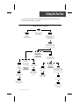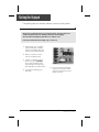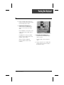
1
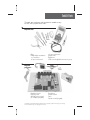
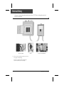
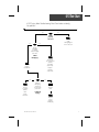
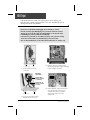
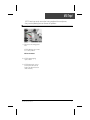
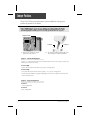
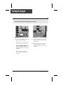
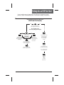
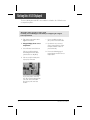
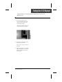
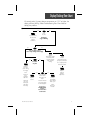
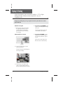
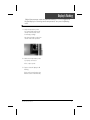
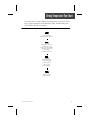
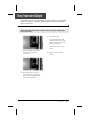
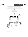
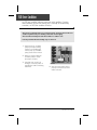
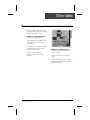
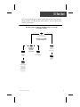
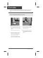
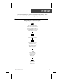
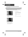
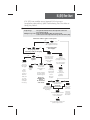
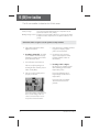
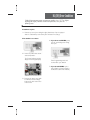
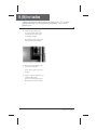
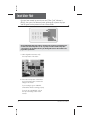
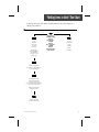
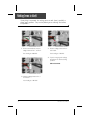
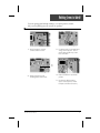
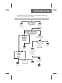
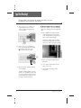
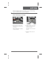
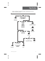
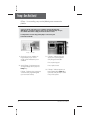
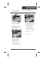
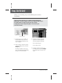
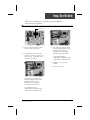
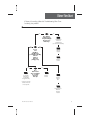
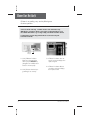
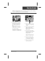
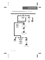
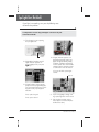
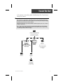
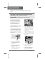
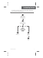
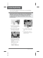
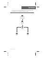
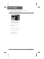
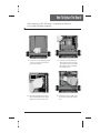
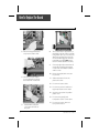
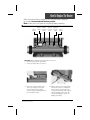
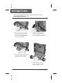
MC-MP SPA SYSTEMS
Service Manual
• by Gecko Alliance •
Visual step-by-step guide to easily
identify & correct technical problems!
Table of Contents
��������������������
�
����������������
�
������������������
�
�������������������������������
��
��
��
������������
�
�����������������
�
����������������������
�
��
��
����������������
�
��������������������������������������������
�
��������������������������������
�
��������������������
�
����������������������������������������������
�
����
�
����
�
����
�
��������
�
������������������
���
��
���
���
���
���
���
���
���
���������������
�
������������������������
�
��������������������
�
������������������������������
�
�����������������������
�
����������������������
�
�������������������������
�
���������������������������������
�
�������������������
���
���
���
���
���
���
���
���
����������
�
������������������
�
����������������������������������������������������������
�
�����������������������
�
���������������������������
���
���
���
���
�������������
�
����������������
�
������������������������������
��
��
�
�
����������������������������������������������������������������������
�������������������������������������������������������������������������
In an attempt to make this manual as useful as possible, it has been presented in two
formats. Problem-solving solutions are described with Troubleshooting Flow Charts
and also with Step-by-Step Procedures.
The two formats together should provide an overall complete explanation, with flow
charts providing an overview of specific problems, and step-by-step procedures giving
more detailed information.
Important Safety Information
WARNING: Risk of electrical shock! All procedures described in this service manual
must only be performed by qualified personnel, in accordance with the
standards applicable in the country of installation and, whenever
possible, with the equipment powered off. When connecting the
equipment, always refer to the wiring diagram affixed to the inside of
your spa pack’s power box cover! This diagram always prevails over
the wiring diagram at the end of this manual.
All information given subject to technical modifications without notice.
Tools & Parts
���������������������������������������������������������
���������������������������������
���������������
������
����������������������������
�����������������
��������������������
��������������������
������������
����������
��������������������������������������������
���������
�����������
�����������������
���������������
������������������
����������������������
�����������
���������������
�����
�������������������������
�������������������������������������������������������������������������������������������������������������
����������������������������������������������������������
Electrical Wiring
Correct wiring of the electrical service box, GFCI box and pack terminal
block is essential.
Electrical Box
GFCI
Pack Terminal Block
1• Carry out a visual inspection to check
for signs of miswiring.
Refer to supplied wiring diagrams.
Call an electrician if necessary.
4
MC-MP Service Manual
GFCI Flow Chart
If GFCI trips, follow Troubleshooting Flow Chart below to identify
the problem:
yes
no
Is GFCI
properly
connected?
yes
Verify
Wiring Diagram
and reconnect it.
no
Unplug
everything,
including
heater and light
cord wires.
Is GFCI
still tripping?
Reconnect
one component
at a time
until GFCI
starts to trip.
Replace
transformer.
Replace
defective
component.
yes
There is
a problem
with the
cable.
Call an
electrician.
no
If GFCI is
still tripping,
disconnect
the incoming
power line.
Replace
GFCI.
Is GFCI still
tripping?
Replace
board
if GFCI is
still tripping.
MC-MP Service Manual
5
GFCI Trips!
If all connections are made, but nothing seems to be working, you
probably have a power supply problem. Carry out the following tests to
identify and correct the problem:
Note that for new installations, GFCI trippings due to miswiring are common.
If breaker is wired properly, GFCI trippings may occur when total amount of current
drawn by spa exceeds breaker rating. This is highly unlikely as each spa pack output
is individually fused, and fuses will blow before GFCI trips.
A current leak to ground will also cause GFCI to trip. If any of the components is faulty
and a leak of more than 5mA occurs, GFCI will trip to prevent electrocution.
There are different GFCI models on the market. Note that illustrations are examples only.
From electrical box
To spa
1• Verify if GFCI is properly
connected.
3• If GFCI is properly connected, but
still tripping, unplug all outputs including
heater and light cord wires.
Important
connections:
Neutral of GFCI
must be connected
to neutral bus.
Neutral from spa
must be connected
to breaker.
From electrical box
To spa
2• If it is not, verify GFCI wiring
diagram and reconnect it.
6
4• If GFCI still trips, replace transformer.
If it stops tripping, reconnect one
component at a time until GFCI
starts to trip. Replace defective
component.
MC-MP Service Manual
GFCI Trips!
If GFCI continues to trip even after having replaced the transformer,
carry out the following tests to correct the problem:
1• Disconnect incoming power
lines.
If GFCI still trips, there must
be a cable problem.
Call an electrician!
2• If GFCI stops tripping,
replace GFCI.
3• If GFCI trips again, replace
board. (Refer to "How to
Replace the Board" section
of this manual.)
MC-MP Service Manual
7
Jumper Positions
Certain MC-MP spa pack parameters can be modified by changing the
position of jumpers on the board.
Remove MC-MP power box cover to access jumpers. (See "How to Replace the Board"
section of this manual). Jumper functions may differ from information below. Please
check wiring diagram on inside pack cover to verify specific functions for our pack.
Jumper Location
Position 1
1• Jumpers are located in upper
right side of the board.
Position 2
2• To change a setting, simply pull cover
off and replace in desired position.
Jumper 1: Current Limiting Option
Jumper 1 is used to limit amount of current drawn when more than one pump (or pump and
blower) are on at the same time.
Position 1 (HC):
Heater will shut down if more than one pump is on at high speed.
Position 2 (LC):
The system will not turn heater on if any pump (1, 2 or 3) is on at high speed.
"Heater" indicator will flash on display indicating that more heat is requested, but heater will
not be allowed to start.
Jumper 2: Keypad Configuration
Position 1:
10-key configuration.
Position 2:
8-key configuration.
8
MC-MP Service Manual
Low Level Programming
�������������������������������������������������������������������������������
�������������������������������������������������������������������������������
����������������������
���������������������������������������������������������������������������������
�������������������������������������������������������������
�������������������������������������������������������������������������
��������������������������������������������������������������������������������
�������������������������������������������������������������������������������
�������������������
��������������������������������
���������
� �������������
� ������������ ����������������
� � � � � �������������
���������
� �������������
� ������������ �����������������
� � ��
�
����������������
� � ��
�
�������������
��������
� �������������
� ������������ �����������������
� � ��
�
���������������������������
� � ��
�
�������������
� � ��
�
����������������������
���������
� �������������
� ������������ �����������������
� � ��
�
��������������
�������������������
� �������������
� ������������ �����������������
� � ��
�
�����������������������
� � ��
�
�
������������
� � ��
�
�������������
� � ��
�
���������������������������
� � ��
�
�
��������������
���������
� �������������
� ������������ �����������������
� � ��
�
����������������
� � ��
�
�������������
� � ��
�
���������������
���������������
� �������������
� ������������ ������������������������
� � ��
�
�������������������������
� � ��
�
�������������������������
� � ��
�
�
��������������
���������
� �������������
� ������������
� � ��
�
� � ��
�
� � ��
�
� � ��
�
� � ��
�
� � ��
�
�������������������������
� �������������
� ������������ ���������������
� � ��
�
�������������������
� � ��
�
�
�����������������������
�����������������
�����������������������������
������������������������������
�����������������������������
�
����������������������
������������������������������
�
�������������������
MC-MP Service Manual
9
10
MC-MP Service Manual
Flashing Dots Flow Chart
If 3 flashing dots appear on keypad display, follow Troubleshooting Flow
Chart below to identify the problem:
3 flashing dots appear on the display!
yes
no
Remove pack cover.
Is board LED on?
Follow
flashing dots
& LED flow chart.
Make sure jumper is
set properly for
circulation pump and
reset breaker.
Start Pump 1 (or
circulation pump if installed
by increasing set point).
yes
no
Do you have
continuity on your
voltmeter for
pressure switch?
yes
Verify
pressure
switch
connection.
Short pressure
switch terminals
with a jumper cable.
no
Disconnect
pressure switch
for 5 seconds
and reconnect it.
Are dots still
flashing on
keypad display?
Replace pressure
switch cable.
yes
Try to adjust
pressure switch.
Replace pressure
switch cable.
Replace pressure
switch if problem
persists.
If problem persists,
replace board.
no
Are dots still
flashing on
keypad display?
Remove anything
obstructing filter canister
or piping. Clear any air
locks. Verify water valves.
Try to adjust
pressure switch.
If problem persists,
replace board.
Replace pressure
switch if problem
persists.
MC-MP Service Manual
11
Flashing Dots Displayed
Three flashing dots error condition indicates a pressure switch problem.
There must be enough water in the spa for normal operations. System may detect error
condition if spa filter is dirty or if something restricts flow of water in piping.
The heater will automatically shut down when error condition occurs.
Power may remain On when the following steps are carried out.
1• Verify if Pump 1 (or circulation
pump if installed) is working. If
pump is not working right, refer
to pump section of this manual.
2• Make sure jumper is set properly for circulation pump.
3• If Pump 1 is working properly,
turn it on by pressing Pump 1
key (or start circulation pump
by increasing the set point) and
test continuity on pressure switch.
4• If you detect continuity, go to
step #10.
12
5• If you do not detect continuity,
verify if pressure switch cable is
properly connected to pressure
switch and board.
MC-MP Service Manual
Flashing Dots Displayed
6• Ensure adequate water flow in the
heater and short two pressure switch
terminals with jumper cable.
7• If the three dots disappear, first
make sure there is no blockage of
water or air lock and check water
valve.
If the installation is older than 2 years,
replace the pressure switch and recalibrate it.
If installation is recent, try readjusting the pressure switch. If this is not
possible, replace switch.
(Refer to "How to Adjust the
Pressure Switch" section of this
manual.)
MC-MP Service Manual
8• If the three dots still appear, the
problem may be either with switch
cable or board.
Remove plastic cover and replace
cable.
9• Replace board if error condition still
persists. (Refer to "How to Replace
the Board" section.)
13
Flashing Dots Displayed
Power may remain On while the following steps are carried out.
10• If you have continuity on pressure
switch, follow these steps:
Disconnect pressure switch cable
for 5 seconds and reconnect it.
If error condition disappears, adjust pressure switch, if it is a new
installation (less than two years) or
replace it.
11• If error condition persists, remove
plastic cover and replace pressure
switch cable.
12• Replace board if error condition
still persists. (Refer to "How to
Replace the Board" section of this
manual.)
(Refer to "How to Adjust the
Pressure Switch" section of this
manual.)
14
MC-MP Service Manual
Flashing dots and LED Flow Chart
��������������������������������������������������������������������������
��������������������������������������������������������������������������
���������������������������������������������������
�����������������������������������������
������������������������������������������
���
��
����������������������
���������������������������
�����������������������
�����������������������������������
���
��
����������
�����������������
�����������
����������������
������������������
��������������������
���������������������
���������������
������������������
�����������������������
������������������
������������������������
������������������������
�����������
�������������������
���������������������
�������������
������������
���������
�����������������
�����������������
�������������������
���������������
��������
���������
�����������������
����������������������
��������������������
������������������
�������
��������
�����
���������
���������������
MC-MP Service Manual
15
Flashing Dots & LED Displayed
The three flashing dots and LED error condition is related to the Hi-Limit sensor
or temperature probe.
Turn breaker off then on again to reset the system.
If 3 flashing dots and LED disappear, wait until they are displayed again on keypad.
Power may remain On.
1• Take water temperature with a
digital thermometer.
c- If error condition persists, replace probe and reset breaker.
2• If keypad display shows correct
temperature:
a- Check if heater barrel feels hot.
d- If problem is not corrected,
replace board. (Refer to "How
to Replace Board" section of
present manual.)
If it's hot, verify if anything is
obstructing the flow of water
(closed valves or dirty filter).
3• Proceed to following page if
keypad display shows incorrect
temperature.
b- If it's not, verify if hi-limit probe
is properly connected.
Try to clean probe connector
pins. Even a small coating of film
can cause a bad connection.
Reconnect probe and reset
breaker.
16
MC-MP Service Manual
Flashing Dots & LED Displayed
If keypad display isn't showing correct temperature, carry out the
following tests:
1• Verify if temperature probe
is in contact with water and if
cold air from the back could
be affecting readings.
Use foam to isolate probe from
cold air if that is the problem.
2• Make sure temperature probe
is properly connected.
If it is, replace probe and reset
breaker.
3• Replace board if error condition
still persists. (Refer to "How to
Replace the Board" section of
this manual.)
MC-MP Service Manual
17
18
MC-MP Service Manual
Display Flashing Flow Chart
On certain packs, if system detects temperature at 112°F or higher, the
display will start flashing. Follow Troubleshooting Flow Chart below to
identify the problem:
yes
A power failure
has occurred.
System
works fine.
no
Press
any key.
Has display
stopped flashing?
yes
no
Are you getting correct
water temp. reading on the display?
yes
no
Is weather
very hot?
Verify if
temperature probe
is touching water
or if cold air from
back can affect
reading.
Remove
spa cover
(even during
the night).
Start
blower, if
spa is
equipped
with one.
Wait until
spa cools
down (add
cold water
if needed).
yes
Replace
board.
MC-MP Service Manual
"Heater" indicator
on keypad display
should disappear.
Do you get a
240 VAC reading
between
two heater wires
on the board?
If so, replace probe
and reset breaker.
Replace
board if
problem
still persists.
no
Lower set point
below actual
temperature of
water.
Verify if
temperature probe
is properly connected.
Pump is
overheating
water during
filter cycle.
Lower
filter cycle
duration.
19
Display Is Flashing
��������������������������������������������������������������������
������������������������������������������������������������
��������������������
���������������������������������������������������������������������������������������������
������������������
�����������������������
��� �����������������������������
� ����������������������������������
� �����������������������������
� ������������������������������
� ��������������
�������������������������������
��� ��������������������������������
� �������������������������������
� �������������
�
�
��������������������������
������������������������������
��� ��������������������������������
� ���������������������������������
� ����������������������������������
� ������
�
�
�����������������������������
�������������������������������
��� �����������������������������
� ������������������
�
�
�����������������������������������
��������������������
��� ������������������������������
� �������������������������������
� ����������������������������������
20
MC-MP Service Manual
Display Is Flashing
If digital thermometer water temperature reading is 112°F or higher and
keypad display isn't showing correct temperature, carry out the following
tests:
1• Verify if temperature probe
is in contact with water and if
cold air from the back could
be affecting readings.
Use foam to isolate probe from
cold air if that is the problem.
2• Make sure temperature probe
is properly connected.
If it is, replace probe.
3• Replace board if display is still
flashing.
(Refer to "How to Replace the
Board" section of this manual.)
MC-MP Service Manual
21
22
MC-MP Service Manual
Wrong Temperature Flow Chart
On certain packs, if system detects that temperature is not within normal
limits, wrong temperature will be displayed. Follow Troubleshooting Flow
Chart below to identify the problem:
Check if regulation
probe is properly connected.
Unplug probe connector
and clean pins on the
board (even a small coating
of film may cause a bad
connection).
Reconnect the probe.
Replace probe with
a spare and verify if
problem is solved.
If it is, replace
probe with spare.
Replace board if
problem persists.
MC-MP Service Manual
23
Wrong Temperature Displayed
Wrong temperature on keypad display indicates a problem with regulation
sensor. The system is constantly verifying if temperature probe reading is
within normal limits.
Note that water temperature must be over 35°F in order to carry out the following steps.
Power can remain On.
3• Reconnect probe.
If wrong temperature is still
displayed, replace probe with
a spare and place probe head
directly in spa water.
If problem is solved, replace
probe.
1• Verify if regulation probe (sensor
located in spa) is properly
connected.
4• Replace board if problem
persists.
2• Disconnect probe connector
and clean probe connector pins.
Even a small coating of film may
cause a bad connection.
24
MC-MP Service Manual
FLO Flow Chart
If FLO error condition occurs (problem with the pressure switch: pump is
on but no water pressure detected), follow Troubleshooting Flow Chart
below to identify the problem:
There must be adequate water
in spa for normal use.
Ensure circulation pump jumper
is set properly (see Jumper Section).
yes
no
Is pump
working?
yes
Refer to "Pump not
Working" section.
no
Is anything limiting
flow of water into pipes?
Remove
anything
obstructing
filter. Clear
any air locks
and verify
water valves.
Verify if
pressure switch
cable is properly
connected
to pressure
switch and
board.
yes
yes
no
Is it a new
installation
(less than
two years)?
no
Ensure flow of
water through heater and
short two pressure
switch terminals with a jumper.
Does FLO
error condition
persist?
Replace
board.
Replace
pressure switch.
Adjust
pressure switch.
MC-MP Service Manual
25
FLO Error Condition
An FLO error condition indicates a pressure switch problem. If system
does not detect any pressure when pump is manually or automatically
turned on, an FLO error condition will occur.
There must be enough water in the spa for normal operations. System may detect an FLO error
condition if spa filter is dirty or if something restricts flow of water in piping.
The heater will automatically shut down when an FLO error condition occurs.
Power may remain On when the following steps are carried out.
1• Verify if pump (or circulation
pump if present) is working.
If pump is not working right,
refer to pump (or circulation
pump) section of this manual.
2• Make sure jumper setting for
circulation pump is correct.
(See Jumper Section).
3• Clean filter and check for air
blockages, closed trap valves or
anything that could be restricting
water flow.
26
4• Verify if pressure switch cable is
properly connected to pressure
switch and board.
MC-MP Service Manual
FLO Error Condition
5• Ensure adequate water flow in the
heater and short two pressure switch
terminals with jumper cable.
6• If FLO error condition disappears,
perform the following steps:
If the installation is older than 2 years,
replace the pressure switch and
recalibrate it.
If installation is recent, try readjusting
the pressure switch. If this is not
possible, replace switch.
(Refer to "How to Adjust the
Pressure Switch" section of this
manual.)
7• If FLO error condition persists, the
problem may be either with switch
cable or board.
Remove plastic cover and replace
cable.
8• Replace board if FLO error condition
still persists. (Refer to "How to Replace
the Board" section.)
MC-MP Service Manual
27
28
MC-MP Service Manual
FLC Flow Chart
If FLC error condition occurs, follow Troubleshooting Flow Chart below to
identify problem (usually pressure switch problem - pump is off but water
pressure is detected):
First ensure jumper position for circulation pump is set correctly
(see Jumper Section).
yes
no
Disconnect
pressure switch cable.
Does FLO error condition
occur when pump is on?
yes
no
Is it a new
installation
(less than
two years)?
Adjust
pressure
switch.
Replace
pressure
switch cable.
Replace
pressure switch.
Replace
board.
Replace
pressure switch
if FLC error
condition
persists when
you start or
stop pump.
MC-MP Service Manual
29
FLC Error Condition
An FLC error condition indicates a pressure switch problem. If the system
detects any pressure when the pump is off, an FLC error condition will
occur.
Power may remain On while the following steps are carried out.
1• First check to ensure jumper position
for circulation pump is set correctly
(see Jumper Section). If not, readjust
jumper.
3• If there is no FLO error condition,
remove plastic cover and replace
pressure switch cable.
Disconnect pressure switch cable.
4• Replace board if FLC error condition still persists. (Refer to "How to
Replace the Board" section of this
manual.)
2• If FLO error condition occurs when
pump is started, adjust pressure
switch, if it is a new installation (less
than two years) or replace it.
(Refer to "How to Adjust the Pressure Switch" section of this manual.)
30
MC-MP Service Manual
Prr Flow Chart
If Prr error condition occurs (potential regulation sensor problem), follow
Troubleshooting Flow Chart below to identify the problem:
Pressing any key after each step resets the system.
Note that water temperature
must be over 35°F to operate spa.
In systems manufactured after 98,
Prr error status is ignored during first
hour after initial power up to allow
water to heat to over 35°F.
Check if regulation
probe is properly connected.
Unplug probe connector
and clean pins on the
board (even a small coating
of film may cause a bad
connection).
Reconnect the probe.
Replace probe with
a spare and verify if
problem is solved.
If it is, replace
probe with spare.
Replace board if
problem persists.
MC-MP Service Manual
31
Prr Error Condition
The Prr error condition indicates a problem with regulation sensor.
The system is constantly verifying if temperature probe reading is
within normal limits.
Note that water temperature must be over 35°F in order to carry out the following steps.
Pressing any key after each step resets system. Power can remain On.
3• Reconnect probe.
If Prr error condition still persists,
replace probe with a spare and
place probe head directly in spa
water.
If problem is solved, replace
probe.
1• Verify if regulation probe (sensor
located in spa) is properly
connected.
4• Replace board if problem persists.
2• Disconnect probe connector
and clean probe connector pins.
Even a small coating of film may
cause a bad connection.
32
MC-MP Service Manual
HL (OH) Flow Chart
If HL (OH) error condition occurs (potential Hi-Limit sensor or
temperature probe problem), follow Troubleshooting Flow Chart below to
identify the problem:
Steady message:
The system has shut down because the temperature at the heater
has reached 119°F (48°C).
Blinking message or OH: Except for the Smart Winter Mode, the system has shut
down because the water temperature in the spa has reached 112°F (44°C).
Turn breaker off then on again to reset the system.
yes
no
Take water temperature
with a digital thermometer.
yes
no
Is water temperature
112°F or higher?
Are you getting correct
water temp. reading on the display?
yes
Verify if
temperature probe
is touching water
or if cold air from
back can affect
reading.
no
Is weather
very hot?
Remove
spa cover
(even during
the night).
Start
blower,
if spa is
equipped
with one.
Wait until
spa cools
down (add
cold water
if needed).
yes
Replace
board.
no
Lower set point
below actual
temperature of
water.
"Heater" indicator
on keypad display
should disappear.
Do you get a
240 VAC reading
between
two heater wires
on the board?
Pump is
overheating
water during
filter cycle.
Lower
filter cycle
duration.
Verify if
temperature probe
is properly connected.
If so, replace probe
and reset breaker.
Replace
board if
HL (OH) error
condition
still persists.
yes
no
When HL (OH) error
condition occurs,
does heater
Verify if anything
barrel feel hot?
is obstructing water
flow (closed traps or
dirty filters).
If HL (OH) error condition
persists, replace probe
and reset breaker.
If HL (OH) error condition still
persists, replace board.
Is HL probe
properly
connected?
Clean pins,
reconnect
it, and reset
the breaker.
HL (OH) Error Condition
The HL error condition is related to the Hi-Limit sensor.
Steady message:
The system has shut down because the temperature at the
heater has reached 119°F (48°C).
Blinking message or OH: Except for the Smart Winter Mode, the system has shut down
because the water temperature in the spa has reached 112°F
(44°C).
Turn breaker off then on again to reset the system. Power may remain On.
1• Take water temperature with a
digital thermometer.
c- If HL (OH) error condition continues
to appear on display, replace
probe and reset breaker.
2• If reading is below 112°F, HL (OH)
error condition should be steady,
indicating a problem at the hi-limit
probe and heater level.
d- If problem is not corrected,
replace board. (Refer to "How
to Replace Board" section of
this manual.)
a- Check if heater barrel feels hot.
If it's hot, verify if anything is obstructing the flow of water (closed
valves or dirty filter).
b- If it's not, verify if hi-limit probe is
properly connected.
3• If reading is 112°F or higher,
HL (OH) error condition should
flash, indicating a problem with
temperature probe.
Proceed to following page if
keypad display shows correct
temperature.
Proceed to page 36 if display
doesn't show correct temperature.
Try to clean probe connector pins.
Even a small coating of film can
cause a bad connection. Reconnect probe and reset breaker.
34
MC-MP Service Manual
HL (OH) Error Condition
�����������������������������������������������������������������������
����������������������������������������������������������������
����������������
�����������������������
��� �������������������������������������������������������������������������
� ������������������������������������������������������������������
�������������������������������
��� ��������������������������������
� �������������������������������
� �������������
��� �����������������������������
� ������������������
�
�
�����������������������������
������������������������������
�
�
��������������������������
������������������������������
��� �������������������������������
� ��������������������������������
� �����������������������������������
��� �������������������������������
� �����������������������������
� ����������������������������
� �������������
MC-MP Service Manual
35
HL (OH) Error Condition
If digital thermometer water temperature reading is at 112°F or higher
and keypad display isn't showing correct temperature, carry out the
following tests:
1• Verify if temperature probe
is in contact with water and if
cold air from the back could
be affecting readings.
Use foam to isolate probe from
cold air if that is the problem.
2• Make sure temperature probe
is properly connected.
If it is, replace probe and reset
breaker.
3• Replace board if HL (OH) error
condition still persists.
(Refer to "How to Replace the
Board" section of this manual.)
36
MC-MP Service Manual
Smart Winter Mode Chart
If pumps have started up on several occasions and "Filter Cycle" indicator
is flashing on keypad, follow this Troubleshooting Flow Chart to identify the
problem:
yes
no
Is the water temperature
of the spa lower than
the desired temperature?
yes
no
Do you
read 240 VAC
to the
heater?
Refer to
"Spa not heating"
section.
System
works
fine.
MC-MP Service Manual
37
Smart Winter Mode
�����������������������������������������������������������������������
������������������������������������������������������������������������
���������������������������������������������������
��������������������������������������������������������������������������������������������������
����������������������������������������������������������������������������������������
������������������������������������������������������������������������������������������������
��������������������������
��� ����������������������������������
� �����������������������������
��� ��������������������������������������
� ������������������������������������
� ����������������������
38
�
�
������������������������������������
��������������������������������������
�
�
�
�������������������������������������
��������������������������������������
�������
MC-MP Service Manual
"Nothing Seems to Work" Flow Chart
If nothing seems to work, follow Troubleshooting Flow Chart below to
identify the problem:
yes
Verify if
keypad is
connected
correctly
to board.
All eight pins
must be plugged in
and black wire
must be on top
of the plug.
no
Do you get a
≈240 VAC reading
between
line 1 & line 2,
≈120 VAC
between
line 1 & neutral,
≈120 VAC
between
line 2 & neutral
on the board?
There is
an electrical
wiring
problem.
Call an
electrician.
Replace transformer
fuse if there is still nothing on
the keypad display.
If nothing still works,
clean the transformer
orange connector pins
(even a small coating of film may
cause a bad connection).
Replace transformer if
problem persists.
Replace board if
problem still persists.
MC-MP Service Manual
39
Nothing Seems to Work!
If everything is connected, but nothing seems to work, there is probably a
power supply problem. Carry out the following tests to identify and correct
the problem:
1• On the terminal block, measure
voltage between line 1 and line 2.
You should get ≈240 VAC.
3• Measure voltage between line 2
and neutral.
You should get ≈120 VAC.
4• If you do not get good readings,
this indicates an electrical wiring
problem.
Call an electrician!
2• Measure voltage between line 1
and neutral.
You should get ≈120 VAC.
40
MC-MP Service Manual
Nothing Seems to Work!
If you are getting good voltage readings, but nothing seems to work,
carry out the following tests to correct the problem:
1• Verify if keypad is correctly
connected to the board.
3• If nothing works, clean transformer
orange connector pins. Even a
small coating of film may cause a
bad connection.
Xfo
fuse
2• Replace transformer fuse
if nothing still seems to work.
4• Replace transformer if problem
persists.
5• If problem is still not solved,
replace board. (Refer to "How
to Replace the Board" section.)
MC-MP Service Manual
41
42
MC-MP Service Manual
"Spa Not Heating" Flow Chart
�������������������������������������������������������������������������
�����������������������������������������
���
��������
����������������
�����������
����������������
��
��������������������
�������������������������������
������������������
���
������������
������������
�����������
������������������
��
����������������������������������
�����������������������������������������
�������������������������������
��������������������
���
��
����������������
������������
����������������������
���������������
���������������������
�������������
�������������
���
��
�������������
����������������������
����������������
���������������������
����������
�������
������
���
��
���
������������
���������
���������
������
��������
�������������
����������������
��������������
��������������������
���������������
������������������
���������������
����������������
���
��
�������
�����������������
�����������
��������������������
�����������������������
�������
��������
������
�����������
������������������
MC-MP Service Manual
�������
�������
�������
������
43
Spa Not Heating!
�������������������������������������������������������������
�������������������������������������������
��� ��������������������������������
� ����������������������������������
� ����������������������������������
� ����������������
����������������������������������������
�������������������������������������
���������������������������������������
������
�
��� ���������������������������������
� �����������������������������
� ���������������������������������
� ����������������������������
�
�
�
�
�
����������������������������������������
��������������������������������������
��������������������������������������
��� ����������������������������������
� �����������������������������������
� �����������������������������
� �����������������������������
����
������
����
��������
���������
��� ������������������������������������
� ����������������
�
�
�
�
�
44
�����������������������������������
����������������������������������������
����������������������������������
�������������������������������������
��������������������������
��������������������������������������
� ����������
��� ���������������������������������
� �����������������
��� ������������������������������������
� ����������
MC-MP Service Manual
Spa Not Heating!
����������������������������������������������������������������������������
�����������������������������������������������������
�����������������������������������������������
��� ��������������������������������
� ���������������������������������
� �������������
��� �������������������������������������
� ���������������������������������
� ����������������������
�
�
�
�
������������������������������������
���������������������
����������������������������������
��������
��� ��������������������������������
� ��������
MC-MP Service Manual
45
46
MC-MP Service Manual
Pump Flow Chart
����������������������������������������������������������������������
������������������������������
���
��������
����������������
������������
����������������
��
��������������
��������������������������
���������������������������
���������������
���
��
�����������
���������
���������
���������
��������������
��������
���������������
�����������
�������������������
����������������������������
������������������������
���������������
���
��
���������������������
��������������
�������������
����������������
������
���������
������������
���
��
�����������������
������������
��������������������������
���
��
�������
�������
���������������
�����������������������������
��������������
����������
������������������
�����������
������������
MC-MP Service Manual
�������
������
47
Pump 1 Does Not Work!
�����������������������������������������������������������������������
��������
��������������������������������������������������������������������������������
�������������������������������������������������������������������������������������
��������������������������������������������������������������������
������������������������������������������������������������������
���������������������
������������������
��� �������������������������������
� ��������������������������������
� �����������������������������������
� ����������
��� ������������������������������
� �����������������������������
� ������������������������������
�
�������������������������
��� ������������������������������������
� ��������������������������������
� �����������
�
����������������������
�
�
�
48
��������������������������������������
���������������������������������
������������������������
��� ��������������������������������
� ������������������������������
� ����������������������������������
� ���������������������
MC-MP Service Manual
Pump 1 Does Not Work!
If Pump1 does not work in any speed, carry out the following tests to
correct the problem:
Pump 1 fuse
1• If Pump 1 does not work in either
speed, replace Pump 1 fuse.
2• If replacing the fuse does not work,
or if Pump 1 works in one of two
speeds, take voltage reading on the
board for both speeds.
3• Turn Pump 1 to high speed and
measure voltage between white
and red wire connectors:
240 VAC pump: P57& P37
120 VAC pump: P48 & P37
The reading shoud be:
≈240 VAC for a 240 VAC pump
≈120 VAC for a 120 VAC pump
4• If voltage is correct, replace
Pump 1.
5• If not, replace board.
Turn Pump 1 to low speed and
measure voltage between white
and black wire connectors:
240 VAC pump: P57 & P64
120 VAC pump: P48 & P64
The reading shoud be:
≈240 VAC for a 240 VAC pump
≈120 VAC for a 120 VAC pump
MC-MP Service Manual
49
Pump 2 Does Not Work!
������������������������������������������������������������������
������������
��������������������������������������������������������������������������������
�������������������������������������������������������������������������������������
��������������������������������������������������������������������
����������������������������������������������������������������������
���������������������
������������������
��� ��������������������������������
� �����������������������������������
� ������������������������������������
� ����������������
��� ������������������������������
� �����������������������������
� ����������������������������������
�
�������������������������
��� ������������������������������������
� ��������������������������������
� �����������
�
����������������������
�
�
�
50
����������������������������������
���������������������������������
������������������������������
��� ��������������������������������
� ���������������������������������
� ����������������������������������
� ������
MC-MP Service Manual
Pump 2 Does Not Work!
If Pump 2 is not working in any speed, carry out the following
tests to correct the problem:
Pump 2 fuse
1• If Pump 2 does not work in either
speed, replace Pump 2 fuse.
2• If replacing fuse does not correct
problem, or if Pump 2 works in one
of two speeds, read voltage on the
board for both speeds.
3• Turn Pump 2 to high speed and
measure voltage between white
and red wire connectors:
240 VAC pump: P58 & P22
120 VAC pump: P45 & P22
The reading shoud be:
≈240 VAC for a 240 VAC pump
≈120 VAC for a 120 VAC pump
4• If voltage is correct, replace
Pump 2.
5• If not, replace board.
Turn pump 2 to low speed and
measure voltage between white
and black wire connectors:
240 VAC pump: P58 & P35
120 VAC pump: P45 & P35
The reading shoud be:
≈240 VAC for a 240 VAC pump
≈120 VAC for a120 VAC pump
MC-MP Service Manual
51
52
MC-MP Service Manual
Blower Flow Chart
���������������������������������������������������������������
������������������������
���
��
�������������
����������������
�������������������
��������������
�����������
���
��
������
����
�����������
��������������
������������������������
���������
���������
���������
����������������
���
�������������
�����������
��������������
�����������������
�������������
���������
�����������
������������������������
�������
�������
�������
������
��
����
��������������
�������������������
�������������
�����������
����������
�������
�������
�������
������
�����
�����������������
�����������������
����������������
�������������
���������
����������
����������
MC-MP Service Manual
53
Blower Does Not Work!
�������������������������������������������������������
�������������������
������������������������������������������������������������������������������������
���������������������������������������������������������������������������������������
����������������������������������������������������������������������������������������
����������������������������������������������������������������������������
���������������������
������
���������
��� ����������������������������
� ���������������������������
� �������������������������
� ��������������������������������
� ������������������������
��� �������������������������������
� ��������������������������
54
��� ������������������������������
� ������������������������������
� ���������������
��� ��������������������������������
� �����������������������������
� �������������������
MC-MP Service Manual
Blower Does Not Work!
If "Blower" indicator lights up on control display, but blower still isn't working,
carry out the following tests to correct the problem:
1• If indicator lights up on keypad
while blower is in high speed,
take voltage reading between
white and black wire connectors:
240 VAC blower: P59 & P43
120 VAC blower: P49 & P43
Your reading should be:
≈240 VAC for a 240 VAC blower
≈120 VAC for a 120 VAC blower
Blower fuse
2• Replace blower fuse if you do
not get a high enough voltage
reading.
3• Replace board if you still aren't
getting a voltage reading.
(Refer to "How to Replace the
Board" section.)
4• If you do get a good voltage
reading, check if you can restart
blower a few minutes after
being turned off.
Replace blower if it does not
start after cool down period.
5• If blower does start up after
cool down, it's possible that it
is not drawing in enough air.
6• Enlarge the opening to allow
more air into blower.
MC-MP Service Manual
55
56
MC-MP Service Manual
Spa Light Flow Chart
������������������������������������������������������������������
�����������������������������������������
���
��
��������
���������������
�������
�����������
���
���
��
�������������
�����������
��������
���������
��������
���
��
������������
���������
���������
������
������������
���������
����������
�������
�������
����������������
�����������
������������������������
�������
�������
��������������������������
���������������������������
��������������
���
�����������
�������������
��
������������
��������������
��������������
��������
�������������
�������������
���������
�����������������
�������
�����������
�����������
����������������
���������������������������
MC-MP Service Manual
57
Spa Light Does Not Work!
����������������������������������������������������������
�����������������������
�����������������������������������������������������������������������
���������������������
��� ����������������������������������
� ���������������������
�������
���������
��� ���������������������������������������
� ����������������������������
� �����������������������������
� ����������
��� ����������������������������������
� ������������������������������������
� ��������������������������������������
� ��������������������������������������
� ��������������������������������
� �������������������������������
� ������������������������������
� ��������������������������������
� �������
����������
��� ������������������������������������
� ������������������������������������
� ����������������������������������
� ���������������������������������
� ����������
58
�
�������������������������
�
����������������������
��� �������������������������������������
� �������������������������������������
��� ���������������������������������
� ��������������������������������
� ��������������������
MC-MP Service Manual
Ozonator Flow Chart
If the ozonator is not working, follow Troubleshooting Flow Chart below to
identify the problem:
If the user turns on a pump, blower or light during a filter cycle, the cycle will be interrupted and
will only resume 40 minutes after last active output has been turned off (automatically or manually).
This delay is to prevent excessive ozonator activation.
During this interval, "Filter cycle" indicator will flash in a different sequence (On: 1/2 sec., Off: 1/2 sec.,
On: 1/2 sec., Off: 1 1/2 sec.).
Also, to prevent excessive water temperature caused by overly long filter cycles, the system will
cancel a filter cycle after 3 hours if water temperature rises more than 2°F above set point. In this
case, "Filter Cycle" indicator flashes on display.
Verify low level programming
to make sure that ozonator
is programmed properly
(see Low Level Section).
no
yes
yes
no
Do you read
120 VAC for
120 VAC ozonator
(or 240 VAC for 240 VAC)
on the board?
Replace
ozonator.
Has
"Filter Cycle"
indicator (steady
indicator light)
appeared
on keypad
display?
Start up
filter cycle.
"Filter Cycle" indicator
(steady indicator light)
should light up
on display.
Replace
ozonator
fuse.
Replace board
if you still
aren't getting
a voltage reading.
MC-MP Service Manual
59
Ozonator Does Not Work!
������������������������������������������������������������������������
��������
������������������������������������������������������������������������������������������
���������������������������������������������������������������������������������������
����������������������������������������������������������������������
����������������������������������������������������������������������������
���������������������
���������������������������������
�����������������������������������
�����������������������������������������
������������������������������������
�������������������������������������
������������������������������������
������������������������������
������������������������������������������
��������������������������������������������
�������������������������������
������������������������������������
������������������������������������������
�����������������������������������������
����������������������������������������
�������������������������������������
����������������������������������������������
���������������
��� ��������������������������������
� ��������������������������������
� ��������������������������
� ���������������������������
�
�
�
����������������
������������������������������
������������������������������
��� ����������������������������������
� ����������������
���������������
���������
��� �������������������������������
� �������������������������������
� �������������������������
� ���������������
��� ����������������������������������
� ��������������������������������
� ����������
� ��������������������������������������
� ������������������������
60
��������
����
��� ��������������������������������
� ��������������������������
��� ��������������������������������
� ��������������������������������
� ��������������������������
� ���������
MC-MP Service Manual
Circulation Pump Flow Chart
��������������������������������������������������������������������������
�����������������������������������������
�������������������
��������������������
�������������������
������������������������
���������������������
��������������������������
��������������������������
���
��
������
����
�����������
������������������
������������������������
�������������
���������
����������
�������
�����������������
�������
�����������
����������
�������
������
MC-MP Service Manual
61
Circulation Pump Not Working!
������������������������������������������������������������������������
�����������������������������
�����������������������������������������������������������������������������������������������
��������������������������������������������������������������������������������������������
��������������������������������������������������������������������������������������
���������������������������������������������������������������������������������������
���������������������
�����������
�����
��� �������������������������������
� ����������������������������
� ������������������������
��� ���������������������������������
� ������������������������������
� ������������������������������
���������������������
��� �����������������������������������
� ��������������������������������
� �����
��� ���������������������������������
� ��������������������������������
� ��������������������
��� �����������������������������
� ��������������������������������
� ��������������������������������
� ������������
� �����������������������
�����������������������������
�
�
�
62
���������������������
�������������������������
�������������������������
MC-MP Service Manual
Keys Flow Chart
���������������������������������������������������������������������������
���������������������������������������������������������
�����������������
�����������������������
������������������
���������������������
�������������
�����������
����������
�������
���
��
��������
��������
�������
�������
MC-MP Service Manual
�������
������
63
Keys Aren't Working!
�����������������������������������������������������������
���������������������������������������
��� ���������������������������
� �����������������������������
� �������������������������
��� ���������������������������
� �������
��� ���������������������������������
��� ���������������������������
��� �����������������������
� ��������������
64
MC-MP Service Manual
How To Replace The Board
�����������������������������������������������������������
������������������������������������
��� ��������������������������������
� ����������������������������
� �������������������
��� �����������������������������
� ��������������������������������
� ������������������������������
MC-MP Service Manual
��� �������������������������������
� ��������������������������������
� ������������������������������
� ������������������������������
� ������������������
��� �������������������������������
� ����������������������������
� ����
65
How To Replace The Board
5• Disconnect high limit sensor
and pressure switch cable.
8•
The circuit board is supported by a
metal plate, with the entire assembly
being held in place by 5 screws (one
attached to ground wire). Remove
screws and disengage the defective
board/plate assembly (Note: transformer remains attached to board.)
9•
Correctly align replacement board/
metal plate assembly with original
screw holes and reattach to board
with 5 screws.
10• Now, reinsert J&J mini connector
to pack side.
6• Disconnect heater output
by removing two screws at
the bottom of circuit board.
11• Switch transformer from one
plate to the other.
12• Re-connect heater cables.
13• Re-connect pressure switch and
high temperature sensor cables.
14• Verify all connections. Reposition
plastic cover.
15• Re-connect keypad(s) and
temperature sensor connections.
7•
66
Unslot AMP or J&J mini
connectors from side of
the pack.
16• Re-connect power cable and
turn power back on.
MC-MP Service Manual
How To Replace The Heater
Follow instructions below to replace an MC-MP pack heater configured
for standard horizontal/front/bottom position.
Note: Make sure to turn power to the pack off before proceeding.
Heater
lock nut
Pressure Heater
Ground High limit
switch connectors connector wing nut Heater
& nuts
& plate lock nut
& nut
Important: Before starting removal procedure be sure to:
• disconnect pack power input cables;
• ensure spa water valves are closed.
1• Use a pair of pliers to disconnect
2 wires (red and green) of cable
connected to the top of Teflon
pressure switch by pulling upwards
(in no particular order).
MC-MP Service Manual
2• Using a 1/4" wrench to hold steady
and a 3/8" wrench to carefully turn,
loosen nuts securing 2 heater connectors to top of blue plastic support
plate. Disengage heater wires. Be
careful not to damage ceramic by
twisting or bending.
67
How To Replace The Heater
�����������������������������������������������������������������
���������������������������������
��� ������������������������������
� ��������������������������������
� ��������������������������������
� ��������������������������������
� ������������������������������
��� ����������������������������
� �����������������������������
� �����������������������������������
� ���������������������������������
��� ��������������������������������
� ���������������������������������
� �������������������������������
��� ���������������������������
� �������������������������������
� ��������������������������
68
MC-MP Service Manual
How To Replace The Heater
Instructions to replace MC-MP pack heater configured for standard
horizontal/front/bottom position.
7• Remove two remaining jam nuts
from each end of the support plate
and remove plate from heater.
8• Finally, replace old heater with new
one, and follow same procedure in
reverse order to connect replacement heater to spa pack.
A few helpful hints when reconnecting:
a) Don't turn wing-nut too tightly, just
enough to hold rubber sensor in
place.
b) When reconnecting wires from
heater to board, it is important to
use two wrenches to hold nuts
steady. Any bending or twisting
may cause damage to ceramic.
Note: We recommend the use of an
adjustable torque wrench (17 lb/in) to
screw the top nut sufficiently. For more
details, log on to:
www.metapacks.com/a_tn.htm
(Tech News #9906)
MC-MP Service Manual
69
How To Replace The Heater
Follow instructions below to replace an MC-MP pack heater in the
vertical/side position.
Note: Make sure to turn power to the pack off before proceeding.
Ground
connection
Heater
connections
High-limit
wing nut
and plate
Lock nut
(attaches
heater
to pack)
Pressure
switch
Important: Before starting removal procedure be sure to:
• disconnect pack power input cables;
• ensure spa water valves are closed.
1• Use a pair of pliers to disconnect
2 wires (red and green) of cable
connected to top of pressure switch
attached to the outside edge of the
heater (in no particular order).
2• Loosen the wing-nut holding the
hi-limit plate and probe in place
centrally located on the outside
of the heater and remove the
probe and plate.
Then loosen pressure switch by
turning counter-clockwise by hand
and remove.
70
MC-MP Service Manual
How To Replace The Heater
Instructions to replace an MC-MP pack heater in the
vertical/side position.
3• Use 1/4" wrench to hold steady and
3/8" wrench to loosen nuts to disconnect 2 heater wire connections. Be
careful not to damage ceramic by
twisting or bending.
5• Remove the last remaining nut
retaining the heater and disengage
heater from spa pack.
6• Replace the defective heater with
a new one, and repeat the same
procedure in reverse order to
reconnect replacement heater
to the spa pack.
A few helpful hints when reconnecting:
a)
Don't turn wing-nut too tightly, just
enough to hold high temperature
sensor in place.
b) When reconnecting wires from
heater to board, it is important to
use two wrenches to hold nuts
steady. Any bending or twisting
may cause damage to ceramic.
4• Use a wrench to remove the ground
cable nut and disconnect the ground
cable wire.
MC-MP Service Manual
Note: We recommend the use of an
adjustable torque wrench (17 lb/in) to
screw the top nut sufficiently. For more
details, log on to:
www.metapacks.com/a_tn.htm
(Tech News #9906)
71
How To Replace The Heater
Instructions to replace an MC-MP pack heater configured for
horizontal/back/bottom position.
Note: Make sure to turn power to the pack off before proceeding.
Heater
lock nut
Pressure
switch
Heater
Ground
connectors connector
& nuts
& nut
High limit
wing nut Heater
& plate lock nut
To change the heater on a spa configured for back/horizontal heater position
follow the same instructions as for the front/horizontal heater position (shown
on previous pages). The main difference is in the position of the blue plastic
support plate, which sits on the top of the heater in the front position, but is
positioned sideways at the bottom of the pack in the back/horizontal position.
Front/horizontal heater position
72
Back/horizontal heater position
MC-MP Service Manual
How To Install a Laing Heater
Follow instructions below to install a Laing heater on MC-MP Metapacks.
1• To install a Laing heater on a
MC-MP Metapack, you will
need pliers, a Phillips screwdriver,
a 11/32" nut driver and a 3/8" open
end wrench.
4• With the heater plate in position,
squeeze the groud cable between
2 nuts (one on top of the other)
with a wrench.
2• Install heater top holders on both
upper sides of the pack. These
holders can be adjusted and should
be fixed only after heater has been
placed in its final position.
5• Hand tight heater cable plastic nut
in place.
3• Slide nylon sleeves into heater
threaded studs.
6• Do the same with the pressure
switch.
MC-MP Service Manual
73
How To Install a Laing Heater
74
7• Snap upper section of heater tube
into top holders.
10• Push hi-limit rubber sensor in place.
8• Tilt bottom part of heater in position.
11• Tilt down hi-limit plastic latch and
screw wing nut.
9• Screw plate nuts at opposite ends of
heater support plate.
12• Connect pressure switch cables.
MC-MP Service Manual
How To Install a Laing Heater
13• Connect ground cable to board.
15• Adjust top holders in their final
position.
14• Connect heater cables to board.
16• Verify heater plate connections and
place pack cover.
MC-MP Service Manual
75
How To Adjust The Pressure Switch
When a voltmeter is available:
1• Set voltmeter to "Ω" (while both
probes are touching one another,
voltmeter should beep to show
there is continuity).
2• Turn Pump 1 off.
3• Do you have continuity on pressure
switch?
If you have no continuity, go to step 4.
If you do have continuity, increase
pressure switch setting by turning
clockwise until voltmeter stops
beeping. Then, increase another
full turn.
4• Turn Pump 1 on at low speed and
wait a few minutes.
If (3) flashing dots do not appear,
you have adjusted the pressure
switch successfully.
If (3) flashing dots appear, decrease
pressure switch setting by turning
counter clockwise until voltmeter
starts beeping (there is continuity).
Then, decrease another 1/4 of
turn. Turn pump off.
The (3) flashing dots should not
appear (restart procedure if (3)
flashing dots appear).
5• When adjustment procedure is
completed, apply Loctite 425 to
the adjustment screw to secure
it in place.
76
MC-MP Service Manual
How To Adjust The Pressure Switch
When a voltmeter is not available:
1• Turn Pump 1 off.
2• Decrease the pressure switch setting
to 0.5 P.S.I. or until three flashing dots
are displayed.
3• Start increasing pressure switch setting
by very slowly turning adjustment
screw clockwise until three flashing
dots disappear, then another full turn.
4• Turn pump on at low speed for 30
seconds; there should be no flashing
dots on display.
5• Turn pump off and wait 30 seconds.
You should not see the three flashing
dots.
6• If you see an error, restart the adjustment procedure.
If you are not able to adjust the pressure switch, change it.
MC-MP Service Manual
77
Wiring Diagram (Horizontal)
The wiring diagram below provides a general idea of MC-MP wiring, but it is important
to note that it may not apply to all systems. The wiring diagram including on inside
power box cover is the one to be used as main reference for the spa you are servicing.
Pump 1
Voltage
Green / Ground
Red / Low Speed
Black / High Speed
White / Com
120 v 240 v
P69 P69
P37 P37
P64 P64
P48 P57
Pump 2
Voltage
Green / Ground
Red / Low Speed
Black / High Speed
White / Com
120 v 240 v
P70 P70
P22 P22
P35 P35
P45 P58
Jumper Settings
Refer to page 8
78
Blower
Voltage
Green / Ground
Black / High Speed
White / Com
120 v 240 v
P72 P72
P43 P43
P49 P49
Ozone
Voltage
Green / Ground
Black / High Speed
White / Com
120 v 240 v
P73 P73
P30 P30
P46 P60
Circulation Pump
Voltage
Green / Ground
Black / High Speed
White / Com
120 v 240 v
P74 P74
P36 P36
P41 P54
Light Connector
Light 1
Light 2
P14
P13
Heater
Black 1
Black 2
Green / Ground
P63
P44
Ground
MC-MP Service Manual
Wiring Diagram (Vertical)
The wiring diagram below provides a general idea of MC-MP wiring, but it is important
to note that it may not apply to all systems. The wiring diagram including on inside
power box cover is the one to be used as main reference for the spa you are servicing.
Pump 1
Voltage
Green / Ground
Red / Low Speed
Black / High Speed
White / Com
120 v 240 v
P69 P69
P37 P37
P64 P64
P48 P57
Pump 2
Voltage
Green / Ground
Red / Low Speed
Black / High Speed
White / Com
120 v 240 v
P70 P70
P22 P22
P35 P35
P45 P58
Pump 3
Voltage
Green / Ground
Black / High Speed
White / Com
120 v 240 v
P71 P71
P21 P21
P40 P53
MC-MP Service Manual
Blower
Voltage
Green / Ground
Black / High Speed
White / Com
120 v 240 v
P72 P72
P43 P43
P49 P59
Ozone
Voltage
Green / Ground
Black / High Speed
White / Com
120 v 240 v
P73 P73
P30 P30
P46 P60
Jumper Settings
Refer to page 8
Circulation Pump
Voltage
Green / Ground
Black / High Speed
White / Com
120 v 240 v
P74 P74
P36 P36
P41 P54
Heater
Black 1
Black 2
Green / Ground
P63
P44
Ground
Light Connector
Light 1
Light 2
P14
P13
79
Professional Repair Kit
All you need in one case!
����������������������������������������
����������������������������������
��������������������������
��
��
��
��
��
��
��
��
��
��
��
��
��
��
��
�������������������
��������������������������
���������������������������
������������������
����������������������
�������������
��������
������������
�����������
�����������
��������
���������
�����������
�����������������������������
�����
���������
������
Clearly Advanced Spa Systems!™
COMPLETE SERVICE
GUIDE WITH STEP-BY-STEP
INSTRUCTIONS ON:
GFCI Troubleshooting
•
Jumper Selection
•
Understanding
& Correcting
Error Conditions
•
System Malfunctions
•
Part Replacement
Instructions
•
& More
Gecko Alliance
450 des Canetons, Quebec City (QC) G2E 5W6
Canada, 1.800.78.GECKO
9225 Stellar Court, Corona, CA 92883 USA
951.667.2000
3-85-7089
www.geckoalliance.com
9919-100435
Rev. 04/07