1
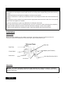
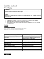
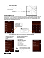
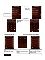
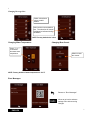
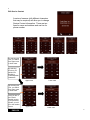
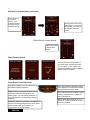
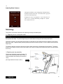
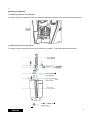
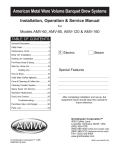
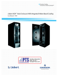
Single Cup Brewer Service Manual Model RC400 Table of Contents Safety Precautions ……………………...2 Installation…………... …………………..3 Power Supply ……..…………………….4 Set –up …………….…………………….4 Advance Settings …….………………...5 Servicing. ……………………………….10 Cleaning and Maintenance …………...21 Troubleshooting………………………...21 QR Codes ……..………………………..24 Spare Parts List..……………………….25 Plumbing diagram ……………………..27 Wiring diagram …………………………28 MODEL: RC400 Prior authorization must be obtained from GMCW for all warranty claims. GRINDMASTER ® BY GMCW ™ © GMCW, 2013 Printed in Thailand GMCW 4003 Collins Lane Louisville, KY 40245 USA (502) 425-4776 (800) 695-4500 (USA & Canada only) FAX (502) 425-4664 www.gmcw.com 1213 Form # BW-306-01 Part # 390-00021 ENGLISH 2 Safety Precautions Important Safety Information This is the safety alert symbol. It is used to alert you to potential personal injury hazards. Obey all safety messages that follow this symbol to avoid possible injury or death. For your safety and the safety of others, read all warnings and the operator’s manual before installing or using the product. DANGER: This term warns of imminent hazard that will result in serious injury or death. WARNING: This term refers to a potential hazard or unsafe practice, which could result in serious injury. CAUTION: This term refers to a potential hazard or unsafe practice, which could result in minor or moderate injury or property damage. NOTICE: This term refers to information that needs special attention or must be fully understood. DANGER To prevent the possibility of electrocution, burns, or other injuries and to prevent damage to your brewer, do not immerse in water or any cleaning liquids. Do not operate a damaged brewer. Inspect the power supply cord and water supply often. If cord or plug is damaged or worn, do not use your brewer. Turn off the water supply and disconnect the electrical power. Turn off and unplug the brewer before cleaning or maintenance. Risk of suffocation. The product packaging contains a plastic bag. Keep plastic bags away from children. Disconnect power if the machine functions abnormally and notify qualified service personnel for repairs. Do not permit non-qualified service personnel to attempt repairs. No user serviceable components inside the brewer. Do WARNING Brew probes are sharp. To prevent injury, do not place fingers inside the brew chamber. The brewer must only be connected to a three wire 120 VAC, 60 Hz, 15 Amp, electrical circuit. Allow brewer to cool before cleaning or maintaining. CAUTION Risk of burns. The brewer uses 185°F- 200°F water that, if not properly handled, could cause burns. Do not permit children to use this appliance unless there is direct adult supervision. Keep away from pets and other animals. For indoor use only. Do not install or use outdoors, in moving equipment, or watercraft. Use the product for its intended purpose only. Any other usage is inappropriate and may be dangerous. The manufacturer assumes no responsibility for injury, loss or damage resulting from improper machine use. To avoid the risk of burns, do not operate without bezel installed. Hot surfaces may cause burns. Do not touch the brewer while in operation. To prevent scalding by hot water, do not open brew chamber while brewing. To prevent scalding by hot water, do not move or tilt the brewer. Moving or tilting the brewer could result in water spilling from the reservoir. Internal boiling is possible at high elevations. You must reduce temperature set point below boiling point for your elevation. To avoid scalding, use appropriate cup rest to minimize splash. Allow a minimum of 1/2” clearance between cup rim and brewer dispense spout to prevent spills when removing a full cup. Center cup with dispense spout while brewing and allow brewer cycle to complete before opening brew chamber or removing cup. To avoid pinching, keep fingers clear of brew chamber when closing. ENGLISH 2 3 NOTICE For best results, remove used Real Cup™ capsule from brew chamber when brewing is complete. Avoid spills by not removing the reservoir while Auto-Fill unit is filling; allow complete filling cycle before removing reservoir. A qualified professional should perform installation, maintenance and repairs. Installation, maintenance or repairs by unqualified personnel may damage the brewer and void the manufacturer’s warranty. This equipment must be installed in accordance with the appropriate national and local codes of the country and/or region in which the appliance is installed. Contact the manufacturer to report any malfunction of or damage to the brewer. When turning the machine off for an extended period, be sure to evacuate the water inside the piping completely, otherwise the water inside the machine could freeze and lead to damage or cause mold to appear. To reduce foreign material from entering the brewer, keep brew chamber and reservoir lids closed. Installation Where to Install Brewer should be installed on a firm, stable, level surface. Keep away from pets. Provide supervision for unattended children and assistance for others that require help to operate the brewer. Water and Power Water Inlet Drain Tube Adapter (Auto-Fill ONLY) Power Switch Power Cord Valve Cap (Pour-Over ONLY) Flare Washer Water Supply NOTICE: The brewer is designed to operate with water pressures from 10 psig up to 100 psig. Grindmaster requires the use of an external water filter such as Water Filter Kit P/N 250-00034. The filter mounts on the rear surface of the brewer. ENGLISH 3 4 Installation (continued) Power Supply WARNING Disconnect power if the machine functions abnormally and notify qualified service personnel for repairs. Do not permit non-qualified service personnel to attempt repairs. No user serviceable components inside the brewer. Do not disassemble brewer. Notice This appliance is equipped with a three wire power cord. A dedicated three wire 120V, 15A NEMA 5-15 electrical circuit must be used. 1. A dedicated 120 VAC, 60 Hz, 15 Amp, type 5-15, electrical circuit is required for proper operation. 2. Always unplug machine before servicing or maintaining the machine. 3. Place power switch in OFF position and plug power cord into the dedicated three wire 120V, 15A, NEMA 5-15 electrical circuit Set-Up Priming the internal hot water tank NOTE: The brewer will not operate until the hot water tank is primed. Please follow these procedures to ensure proper installation. Pour- Over version 1. Ensure that the water inlet valve cap supplied with the machine is installed on the water inlet valve to prevent leaking. 2. Open reservoir lid. 3. Fill reservoir with tap or bottled water to the level indicated on reservoir. Do not use distilled water. 4. Plug unit into a 120V/15 amps receptacle. Turn main power switch to ON. 5. Place a cup in the drip tray of the unit to collect the water from the priming operation. 6. The screen will display "Prime Brewer", press BREW button continue until screen displays "Lift to Brew”. 7. Refill the reservoir to the appropriate level. Auto-Fill version 1. Plumb water to the fill valve located on the back of the brewer. A ¼” female flare x ¼” tube adapter as well as a ¼” flare x hose adapter provided with the brewer. Do not use reverse osmosis water. 2. Open water service valve. 3. Plug unit into a 120V/15 amp receptacle. Turn main power switch to ON. 4. Reservoir will automatically fill. 5. Place a cup in the drip tray of the unit to collect the water from the purging operation. 6. The screen will display "Prime Brewer", press BREW button continue until screen displays "Lift to Brew". 7. Allow brewer to reach brewing temperature. 8. Allow brewer to reach brewing temperature. ENGLISH 4 5 Note: Auto-Fill ONLY: The water is supplied directly to the unit and the water fill level marking is not used. Operation is not affected by the water being below the fill line. Fill Level Advance Settings: The advance setting feature is available to authorized service agents only. It allows changes beyond the skills of the regular end user. It is only accessible via a passcode and allows the technician to change the passcode, change beverage options, beverage size options, water temperature, brew count, review error messages, modify service contact information, and adjust dispense volumes. This icon allows to enter the advanced settings This icon allows to go back to the “Lift to Brew” screen. To access the advanced settings screen, type in the factory default passcode: 0400 The brewer brings you to the Advance Settings screen There are eight options within the Advance Settings Menu: Set passcode Beverage Type Options Beverage Size Options Water Temperature Brew Count Error Messages Service Contact Adjust Dispense Volumes Allows to go back to main set up screen, on previous page, without saving changes. Allows to go back to main set up screen, on previous page, and save changes. ENGLISH 5 6 Setting a new passcode: Select “Set Passcode” This selection takes you back to the basic settings screen. Re-Enter new Passcode Enter new Passcode Changing Beverage Type: Depicts selected beverages. Unselected beverages will not show on Beverage selection ENGLISH NOTE: Factory Default beverage is COFFEE Note that if you had unselected “Ice Tea” the selection would not show up on the Select Your Beverage screen. To set default beverage, select the one of choice. The selection will remain highlighted to indicate it being the default. 6 7 Changing Beverage Size: Select or deselect a size to enable/ disable Select a size to set as default size. The selection will remain highlighted to indicate it being the default. NOTE: Factory default size is 8 oz Changing Water Temperature: Press “+” or “-” to increase/ decrease water temperature Changing Brew Count: Allows to reset the counter NOTE: Factory default of water temperature is 195 °F Error Messages: Returns to “Error Messages” Allows to go back to advance settings menu without saving changes. ENGLISH 7 8 Edit Service Contact A series of screens (with different characters that may be required) will allow you to change Service Contact information. There are two lines for name and address and one line for phone number. By selecting this icon, you switch from upper case to lower case. By selecting this icon, you switch from English to French/Spanish characters. Upper case Lower case By selecting this icon, you switch from upper case to lower case. Once you are in the French/ Spanish screen, if you press this symbol, you will go to the number screen. ENGLISH Upper case Lower case 8 9 Edit Service Contact Name (continued): Once you are in the number screen, if you press this symbol, you will go to the character screen. Once you are in the character screen, if you press this symbol, you will go to the English characters screen. Editing Service Contact Number: Input new number using numeric screen Reset Factory Default: When in Restore Factory Default, if you select reset, the brewer will ask you to confirm. If you confirm, the brewer will display a screen indicating that the reset is complete. Brew Button Color Indications: RED-BLUE-GREEN: The initial start does a RED-BLUE-GREEN sequence. YELLOW: If the brew chamber is open or the display is in the advance settings, the brew button will show yellow. GREEN: When in the brew selection screen AND the hot tank is at temperature, it is steady green. It is also steady green at the end of a dispense. It pulses green during a dispense. RED: When the brew is heating in many screens, it will pulse red. If there is a fault, it will flash red. ORANGE: When in “Lift to Brew”, the instructions screens, the basic settings screens or the More Options screen AND the hot tank is at temperature, it is steady Orange. ENGLISH AQUA: When the hot tank is low, it is steady on. When the reservoir is low or removed, it flashes. 9 10 Adjusting Brew Volumes: This option will allow you to change Brew Volumes factory default as much as ten percent. You will be able to go up ten percent or down ten percent. Example: For 10 oz, if you adjust to +10, it will set the volume to 11 oz. If on the other hand, you adjust to –10, then the volume will be 9 oz. Servicing: This section covers basic instructions for replacing normally serviceable parts. 1) Replacing inlet or outlet probe seals. Warning Brew probes are sharp. To prevent finger injury be careful when servicing inlet and outlet probe seals. Open brew chamber, pull inlet probe seal (located on underside of brew chamber and surrounding the inlet probe) away from probe. Replace seal by carefully pushing the new one onto the probe. Push on sides of seal to prevent finger injury. To replace outlet seal, reach into the brew cup with needle nose pliers, pull seal away from the probe. To replace, gently push on edges of seal (care should be taken not to push on probe) with needle nose pliers until seal bottoms out on cup. 2) Replacing drip tray assembly: Pull drip tray assembly away from brewer. To replace, line up drip tray with internal walls of brewer and slide into until tray hit rear wall of cavity. (See figure below for items 1 and 2) ENGLISH 10 11 Servicing (continued): 3) Replacing flip down Grid assembly. To replace the grid sub-assembly, follow the steps as outlined below with the use of a small flat head screwdriver. 4) Replacing reservoir components. To replace reservoir components, first remove reservoir from brewer. Follow the steps as outlined below. ENGLISH 11 12 Servicing (continued): Warning The next section covers instructions for replacing internal components in the brewer. Always unplug machine before servicing any internal parts. 5) Servicing internal brewer components. In order to service any of the components in the following section, you will first have to gain access to the interior of the brewer. Follow the instructions below to gain access. Remove the panels following the sequence outlined below. For reassembly, execute the sequence in reversed order. You will need a Phillips screw driver. ENGLISH 12 13 Servicing (continued): 5a) Servicing check valve or 3-way valve. These two components are located on the upper rear section of the brewer. To replace the check valve: 1. Cut strain relief straps using wire cutters. 2. Pull inner and outer tubes away from check valve using needle nose pliers. Follow the sequence in reverse when replacing. Make sure tubing is secured and new straps are installed. Check for leaks by running brewer. To replace 3-way valve: 1. Disconnect the two black wires on the solenoid from the main wire harness. You may have to cut the strain relief strap. 2. Cut strain relief straps located on inlet and outlet tubing using wire cutters 3. Remove tubing from the inlet and two outlet ports. 4. Unscrew the valve from the base. Follow the same sequence in reverse to reassemble. Please make sure new strain relief straps are installed on inlet, outlet ports, and main wire harness. Check for leaks by running the brewer. ENGLISH 13 14 Servicing (continued): 5b) Servicing air pump and relief valve. These two components are located on the upper rear section of the brewer, to the left of the 3-way valve when viewed from rear. To replace the air pump: 1. Cut the strain relief on the top of the air pump. 2. Disconnect tubing going to check valve. 3. Lift air pump from its grommet. Follow the sequence in reverse when replacing. Make sure tubing is secured and new straps are installed. To replace the relief valve: 1. Cut the strain relief on the side of the relief valve going to the 3-way valve. 2. Disconnect tubing going to 3-way valve. 3. Gently lift the relief valve from its cradle. Cut the strain relief on the lower tube. 4. Disconnect the lower tube and raise valve away from home base. 5. Cut the strain relief on the upper tube. 6. Disconnect upper tube. Follow the same sequence in reverse to reassemble. Please make sure new strain relief straps are installed on all three tubes. Check for leaks by running the brewer. ENGLISH 14 15 Servicing (continued): 5c) Servicing flow meter and water pump. These two components are located on the lower left area of the brewer when viewed from rear. To replace the flow meter: 1. 2. 3. 4. Disconnect wire connector on the top of the flow meter. Cut the strain reliefs on both inlet and outlet of flow meter. Disconnect the tubing from both inlet and outlet ports. Pull up on flow meter to remove from cradle. Follow the sequence in reverse when replacing. Make sure tubing is secured and new straps are installed. Check for leaks. To replace the water pump: 1. 2. 3. 4. Disconnect wire connector on the top of the water pump. Cut the strain reliefs on both inlet and outlet of water pump. Disconnect the tubing from both inlet and outlet ports. Remove water pump. Follow the same sequence in reverse to reassemble. Please make sure new strain relief straps are installed. Check for leaks by running the brewer. ENGLISH 15 16 Servicing (continued): 5d) Servicing Bezel and Capsule Holder. These two components are located in the brew chamber. To replace the Bezel. Pull on one of the rear corners and pull part away from the lip of the carrier. To replace, line up the slot on the bezel with the lip of the carrier, rotate, and snap into position. To replace the Capsule holder. Push the base of the capsule holder with one of your index fingers to unsnap the part from the carrier. To replace, place in carrier and snap the part into the carrier. 5e) Servicing Probe Holder assembly. This assembly is also located in the brew chamber. Follow the directions below to service: Cut the strain relief straps from inlet and outlet Remove both tubes from inlet and outlet Remove the two screws that secure probe holder assembly to carrier. ENGLISH 16 17 Servicing (continued): The sketch below shows the bypass kit on the probe holder assembly. To service by pass on probe holder assembly: Pull the Manifold Fitting away from the probe holder. Remove the bypass parts. Replace the spring, ring, and ball as shown. Please make sure that the spring is sitting properly inside of the manifold fitting. If is not, the bypass will not operate properly. 5f) Servicing the Linear Damper and the Interlock Switch. This assembly is located behind the brew chamber. Follow the directions below to service: ENGLISH 17 18 5g) Access to the electronics module: a) Loosen the upper screw (pointing to 1) and pull the clamp up. This will allow you to remove the clamp and the electronic housing. b) Remove the four screws on the back of the electronics module. This will give you access to all the components in this module. Reverse sequence to reassemble unit. ENGLISH 18 19 Servicing (continued): 6) Servicing the water inlet valve, the USB board, and the power cord. In order to gain access to these parts, you will have to follow the sequence below: 6a) Servicing the water inlet valve, the USB board, and the power cord. Follow the sequence outlined below to gain access to these components. Reverse order for reassembly. ENGLISH 19 20 Servicing (continued): 6b) Servicing the Triac assembly and the Transformer Follow the sequence outlined below to gain access to these components. Reverse order for reassembly. 6c) Servicing the Tank Assembly Follow the sequence outlined below to gain access to the Tank Assembly. Cut the strain relief straps on the upper and lower hoses, pull hoses from tank, and disconnect all wiring. Reverse order for reassembly. Replace all strain relief straps. Turn brewer on, purge, and check for leaks. ENGLISH 20 21 Cleaning and Maintenance WARNING Brew probes are sharp. To prevent injury, do not place fingers inside the brew chamber. To reduce foreign material from entering the brewer, keep brew chamber and reservoir lids closed. Cleaning: NOTE: When cleaning the unit, do not use cleansers, liquid bleach, powders, or any other substance that contains chlorine. These products promote degradation of plastic parts. Use of these products will void the warranty. Empty the drip tray and reservoir tank as needed and wash in a solution of dish detergent and water, rinse thoroughly. All external parts can be cleaned with a soft, damp cloth. Do not use any abrasives. They will scratch the external surfaces. Do not immerse machine in water. Do not place brewer into a dishwasher. Draining: This action will clear water from the brewer. Power off brewer. Allow brewer to cool. Close water supply valve (Auto-Fill only) and disconnect water line. Remove and empty reservoir. Place a cup under the brew chamber, hold down reservoir detection switch and start a brew sequence. Continue brew sequence until water stops flowing into the cup or until Water Flow Error is displayed. Remove back panel, uncap drain line and drain tank. Recap and replace back panel. Descaling: 1. Close water supply valve (Auto-Fill models only), empty reservoir, empty brew chamber. 2. Fill reservoir with 72 oz. of distilled white vinegar. 3. Using the 12 oz. cycle, operate brewer until "Fill Reservoir" notification appears. 4. Power off brewer – Empty reservoir and rinse thoroughly. Allow brewer to remain off for 3 hours before performing Step 5. 5. Remove back panel, uncap and drain tank. Recap and replace back panel. 6. Fill reservoir with fresh water and return to brewer. 7. Flush brew chamber with 12 oz, of fresh water. Close brew chamber when finished. 8. Power on brewer, open water supply valve (Auto-Fill models only). 9. Follow on screen instructions and prime brewer. 10. Proceed with 12 oz brews until water returns to normal smell and taste. 11. Allow system to refill automatically with plumbing. Troubleshooting The table below lists probable causes and solutions for the most common issues that may be encountered during operation of the Single Cup Brewer. WARNING Disconnect power to electrical equipment any type service of brewer is required. Make sure that brewer is unplugged before servicing. If electrical testing is required, proceed with extreme caution. If brewer requires disassembly, make sure that all parts are properly replaced and that all tags and/or safety labels are replaced as well. Brew probes are sharp. To prevent injury, do not place fingers inside the brew chamber. ENGLISH 21 22 Troubleshooting (continued): PROBLEM SOLUTION No power Verify unit is plugged to a 120V/15 amp rated outlet and power switch in the ON position. 1. Make sure water is turned on. 2. Make sure water pressure is above 20 PSI 3. Clean out any debris at the water inlet behind the brewer. 4. Make sure power is reaching solenoid valve and that the solenoid valve is working. Replace solenoid if necessary. Time to fill longer than expected Refill water tank (Pour-Over model ONLY) Add water to proper level on reservoir. Refill water tank (Auto-Fill model ONLY) Make sure that the water shut off valve is opened. Brew volume is less than normal Adjust volume of beverage on screen. If error persists, perform descaling procedure. Ensure reservoir tank is not filled above maximum fill level. Perform descaling procedure. Water drips from machine when not brewing Water drips from machine (Pour-Over model ONLY). Water leaks from machine while brewing Will not sense unit is primed Unit will not heat Unit overheats or boils Capsule ruptures Clear or weak coffee is dispensed ENGLISH If Pour-Over model, ensure the water inlet valve is capped with the cap that has been provided with the brewer. Remove drain tube cover and verify that the drain line is properly plugged Water conductivity is too low for level sensing circuit. Do not use RO, DI or distilled water. Hi-limit tripped. Check and repair heating circuit to determine fault before resetting hi-limit thermostat. Check level probe has not shorted to tank to allow dry-fire. Triac failure. Temperature set point too high. Reduce temperature set point at least 5 degrees and re-check. 1. Clogged outlet. Clean outlet probe with a paper clip and rinse thoroughly. 2. Faulty capsule seal. Determine if isolated to specific product capsules. 3. Sticking pressure bypass valve. Lubricate seal and ball with food grade silicone lubricant. 4. Faulty capsule seals. 5. Soluble capsule product is not compatible with brewer. Determine if isolated to specific product capsules. 6. Capsule holder is not snapped into carrier correctly. Ensure capsule holder is completely secured onto carrier. 1. Pressure bypass is leaking or stuck open. 2. Upper inlet probe is clogged. Gently insert a paper clip into probe with caution not to disturb duckbill check valve; run a water cycle to clear the probe. 22 23 PROBLEM SOLUTION Water is leaking from unit when dispensing 1. Faulty air pump check valve. 2. Drain tube plug is not installed. 3. Internal leak in plumbing circuit. Remove panels and observe for signs of leakage (water drops or residual calcium deposits) Reservoir not installed properly. Ensure reservoir is installed flush with left side of brewer to ensure engagement of presence switch. 1. Missing level float in reservoir. Replace float in reservoir. 2. Water supply turned off to machine. Restore water supply to machine. 3. Machine is waiting manual refill. Refill reservoir manually. 1. Capsule holder is not snapped into carrier correctly. Ensure capsule holder is completely snapped into carrier. 2. Brew chamber was not fully latched. Ensure the latch is snapped into position during closure. Display indicates replace reservoir Display indicates low or no water. Brew chamber opens while brewing ENGLISH 23 24 Error Codes Engineering Department Erros codes for Mother Parker's Single Cup Brewer QR code SOURCE PROBLEM TO BE PERFORMED BY QUALIFIED SERVICE TECHNICIAN PROBABLE CAUSE CORRECTIVE ACTION 1 Tank Heat timeout Heater failure Harness opens Triac board failure Limit switch open Control board failure 2 3 Measure resistance across heater leads. If open, replace tank assem‐ bly. Check conductivity between heater leads and board. Replace if needed. Replace triac board Replace tank assembly Replace control board No / low water flow Pump failure Harness opens Control board failure Apply 24VAC to pump to check operation. Replace if needed. Check conductivity between pump leads and board. Replace if needed. Replace control board Tank Over‐ Temperature Scale build up in tank assembly Triac board failure Use of hot water in reservoir Delime tank or replace tank if needed. Replace triac board Check user interaction Hot water bypassing into reservoir while brewing Check high pressure bypass check valve. Pull tube off of top of tank and blow air towards reservoir. If air comes out, replace. Pressure is 11PSI nominal. 4 Open thermistor Brewer will not operate at all 5 General fault Various ENGLISH Check thermistor harness connec‐ tion. Measure thermistor resis‐ tance 30K @ 75F. Replace tank assembly if needed. Check latest service materials on website 24 25 Spare Parts List See Part numbers on the next page ENGLISH 25 26 ITEM NO. PART NUMBER 1 210-00030 Drip Tray- single Cup 2 210-00031 GRID- SINGLE CUP DESCRIPTION 3 230-00004 Flip down grid sub-assembly 4 210-00004 Bezel 5 B256A 6 230-00001 COVER, USB PORT Reservoir sub-assembly 7 210-00052 Float guide 8 230-00021 Float assembly 9 280-00001 VALVE, DW15 CHECK 10 210-00051 Reservoir 11 280-00004 Valve, 3-way 24vac 12 280-00005 VALVE, 1/8 X 1/8 BARB CHECK 13 310-00000 Air Pump, 6vdc micro 14 230-00019 Relief valve sub-assembly 15 230-00010 Mechanism cover 16 230-00016 Probe holder assembly 17 310-00002 Pump 18 344-00002 FLOWMETER 19 230-00013 Tank assembly-single cup 20 348-00004 Triac assembly - Single cup 21 280-00007 VALVE, 24VAC WATER INLET 22 348-00003 USB PCB 23 343-00009 Power Cord- 16-3 SJT NEMA 5-15P 24 343-00017 Harness-Single cup heater 25 359-00031 FITTING, ASSY, 1/4 FL X 3/4 HS, SS 26 356-00004 DAMPER, LINEAR 27 230-00028 Kit, Single Cup drip tray & gr 28 210-00235 Cap, Molded inlet valve 29 230-00029 Kit, Inlet fitting and flare washer 30 210-00230 Reservoir rotating lid-NSF 31 210-00233 Reservoir stationary cover 32 380-00068 LABEL, WARNING, HOT LIQUID 33 348-00006 Control-Single Cup Brewer 34 348-00008 PCB- Single Cup display 35 345-00007 LCD display- capacitive 3.5" 36 362-00000 TUBING, 1/8" ID X 1/4" OD 37 362-00001 TUBING, 3/16" ID X 5/16" OD 38 210-00101 Plug- drain tube 39 230-00030 Kit, Single Cup drain cover & 40 230-00031 Kit, capsule seals 41 230-00032 Kit, Bypass seal, ball, spring 42 346-00003 Transformer, 40va 120/24 vac 43 356-00009 Standoff-0.156 dia hole x 3/16 44 354-00003 CLAMP, TO-220 HEAT SINK 45 230-00015 Capsule holder sub-assembly ENGLISH 26 27 Single Cup Brewer Plumbing Diagram ENGLISH 27 28 Single Cup Brewer Wiring Diagram ENGLISH 28