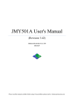
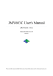
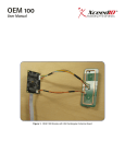
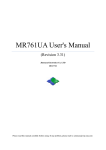
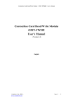
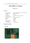
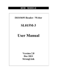
1
ISO15693 CONTACTLESS, ISO7816 CONTACT IC CARD READ/WIRTE READER MODULE JMY680G IC Card Reader User’s manual (Revision 3.50) Jinmuyu Electronics Co. LTD 2012/6/28 Please read this manual carefully before using. If any problem, please mail to: [email protected] ISO15693 & ISO7816 Module http://www.jinmuyu.com Contents 1 2 3 4 5 Product introduction ................................................................................................................................ 3 Characteristics ......................................................................................................................................... 3 Physical parameter and pin outs .............................................................................................................. 4 3.1 Photo........................................................................................................................................ 4 3.2 Dimension ............................................................................................................................... 4 3.3 Pin configurations and pin outs ............................................................................................... 5 3.4 Model available ....................................................................................................................... 5 3.5 Model naming rule .................................................................................................................. 5 3.5.1 Model format ................................................................................................................... 5 3.5.2 Card operating type ......................................................................................................... 5 3.5.3 Communication port ........................................................................................................ 6 Communication Protocols ....................................................................................................................... 7 4.1 Overview ................................................................................................................................. 7 4.2 UART protocol ........................................................................................................................ 7 4.2.1 Parameters ....................................................................................................................... 7 4.2.2 Data send format ............................................................................................................. 7 4.2.3 Data return format ........................................................................................................... 7 4.3 IIC protocol ............................................................................................................................. 8 4.3.1 Module IIC address and multi device communications .................................................. 8 4.3.2 IIC device operation ........................................................................................................ 8 4.3.2.1 Clock and data transaction....................................................................................... 8 4.3.2.2 Start condition ......................................................................................................... 8 4.3.2.3 Stop condition.......................................................................................................... 8 4.3.2.4 Acknowledge (ACK) ............................................................................................... 9 4.3.2.5 Bus state .................................................................................................................. 9 4.3.2.6 Device addressing.................................................................................................... 9 4.3.2.7 Write data operation ................................................................................................ 9 4.3.2.8 Read data operation ................................................................................................. 9 4.3.3 Data transaction ............................................................................................................. 10 4.3.4 Data send format ........................................................................................................... 10 4.3.5 Data return format ......................................................................................................... 10 4.3.6 Description of IIC command transaction....................................................................... 10 Description of commands...................................................................................................................... 12 5.1 List of commands .................................................................................................................. 12 5.2 Explanation of commands ..................................................................................................... 13 5.2.1 Read product information .............................................................................................. 13 5.2.2 Module working mode set ............................................................................................. 13 5.2.3 Set module idle .............................................................................................................. 14 5.2.4 Set LED ......................................................................................................................... 14 5.2.5 Set buzzer ...................................................................................................................... 15 5.2.6 EEPROM read ............................................................................................................... 15 5.2.7 EEPROM write.............................................................................................................. 16 Copyright © 2003-2012 Jinmuyu Electronics Co., LTD. All rights reserved. 1/42 ISO15693 & ISO7816 Module http://www.jinmuyu.com 5.2.8 Set UART communication baud rate ............................................................................. 16 5.2.9 Set IIC communication address ..................................................................................... 16 5.2.10 Set multi-card operation ................................................................................................ 17 5.2.11 Set ISO15693 automatic detecting card AFI and AFI enable ........................................ 17 5.2.12 Set automatic detecting card interval time .................................................................... 18 5.2.13 Set the default automatic detect card state default......................................................... 18 5.2.14 Set automatic detect card and output card UID default ................................................. 18 5.2.15 SAM slot default baud rate set ...................................................................................... 19 5.2.16 SAM reset ...................................................................................................................... 19 5.2.17 Set SAM baud rate after reset (through PPSS) .............................................................. 20 5.2.18 Send APDU to SAM...................................................................................................... 20 5.2.19 ISO15693 inventory ...................................................................................................... 20 5.2.20 ISO15693 stay quiet ...................................................................................................... 21 5.2.21 ISO15693 get system information ................................................................................. 21 5.2.22 ISO15693 reset to ready ................................................................................................ 22 5.2.23 ISO15693 read blocks ................................................................................................... 22 5.2.24 ISO15693 write blocks .................................................................................................. 22 5.2.25 ISO15693 block lock ..................................................................................................... 23 5.2.26 ISO15693 AFI write ...................................................................................................... 23 5.2.27 ISO15693 AFI lock ....................................................................................................... 23 5.2.28 ISO15693 DSFID write ................................................................................................. 24 5.2.29 ISO15693 DSFID lock .................................................................................................. 24 5.2.30 ISO15693 get blocks security ........................................................................................ 24 5.3 About the automatic detecting card ....................................................................................... 25 5.4 Example of commands .......................................................................................................... 25 5.4.1 About UART communication protocol ......................................................................... 25 5.4.2 UART commands sample .............................................................................................. 25 5.4.3 IIC commands sample ................................................................................................... 25 5.5 Interface program source code .............................................................................................. 26 Copyright © 2003-2012 Jinmuyu Electronics Co., LTD. All rights reserved. 2/42 ISO15693 & ISO7816 Module http://www.jinmuyu.com 1 Product introduction JMY680G is a RFID read/write module with UART, IIC, RS232C or USB port. JMY680G has various functions and supports multi ISO/IEC standard of contactless card. The RF protocol is complex, but the designer combined some frequent used command of RF card and then user could operate the cards with full function by sending simple command to the module. The modules build in SAM slot. It could operate contact smart card according to ISO7816. The module and antenna is integrated. The impedance between RF circuit and antenna was tuned by impedance analyzer, and then the module has excellent performance and stability. There is ferrite plate between main PCB and antenna, so such design applies to some metallic-around systems. 2 Characteristics PCD model: NXP SL RC400 Working frequency: 13.56MHz Supported standard: ISO15693, ISO7816 Card supported: TI Tag It, I. Code SLI, ST LRI and other tags according to ISO15693, and ISO7816 SAM cards (both T=0 & T=1) Anti collision ability: Full function anti collision; be able to process multi-cards; be able to set operate single card only Auto detecting card: SAM slot: SAM baud rate: ISO7816 PPSS set: EEPROM: Power supply: Interface: Communication rate: Supported, default OFF. The default state can be set 1 slot 9600bps/38400bps supported 512 Bytes DC 5V (±0.5V) IIC/UART/RS232C/USB (select while place order) IIC: 400Kbps UART/RS232C/USB: 19.2Kbps/115.2Kbps Max. command length: Interface level: Static power consumption: Operating distance: Dimension: Weight: ISP: Operating temperature: Storage temperature: RoHS: 254 Bytes UART/IIC: 3.3V (TTL level; 5V tolerance) 150mA 80mm (depending on card) 70mm*50mm*16.5mm About 120g Supported -25 to +85°C -40 to +125°C Compliant Copyright © 2003-2012 Jinmuyu Electronics Co., LTD. All rights reserved. 3/42 ISO15693 & ISO7816 Module http://www.jinmuyu.com 3 Physical parameter and pin outs 3.1 Photo 3.2 Dimension Copyright © 2003-2012 Jinmuyu Electronics Co., LTD. All rights reserved. 4/42 ISO15693 & ISO7816 Module http://www.jinmuyu.com 3.3 Pin configurations and pin outs Pin number Function Type Description 1 ICC Output Card in/out indication 0: Card IN; 1: Card OUT 2 TXD/SDA Input/output RS232C TXD / UART TXD / IIC SDA 3 RXD/SCL Input RS232C RXD / UART RXD / IIC SCL 4 VCC Power VCC 5 GND Power GND 3.4 Model available JMY680GI JMY680GT JMY680GS JMY680GU IIC interface UART interface, TTL level RS232C (UART interface, RS232 level) USB to UART Bridge (Mini USB port with 5 pins) 3.5 Model naming rule 3.5.1 Model format 1 2 3 4 JMY 680 X X 1: company code; 2: product series code; 3: card operating type; 4: communication port type 3.5.2 Card operating type M: PCD is RC500, support Mifare Class A: PCD is RC500, support ISO14443A and Mifare Class C: PCD is RC531, support ISO14443A, ISO14443B and Mifare Class G: PCD is RC400, support ISO15693 H: PCD is RC632, support ISO15693, ISO14443A, ISO14443B and Mifare Class D: PCD is RC500, support ISO14443A and Mifare Class with 511 bytes communication buffer E: PCD is RC531, support ISO14443A/B and Mifare Class with 511 bytes communication buffer F: PCD is RC632, support ISO15693, ISO14443A, ISO14443B and Mifare Class with 511 bytes communication buffer Copyright © 2003-2012 Jinmuyu Electronics Co., LTD. All rights reserved. 5/42 ISO15693 & ISO7816 Module http://www.jinmuyu.com 3.5.3 Communication port I: IIC T: UART S: RS232C U: USB Copyright © 2003-2012 Jinmuyu Electronics Co., LTD. All rights reserved. 6/42 ISO15693 & ISO7816 Module http://www.jinmuyu.com 4 Communication Protocols 4.1 Overview There are optional IIC, UART or RS232C 3 types’ hardware interface between the module and host. The communication rate of IIC is high. Moreover, IIC mode is very convenient, user may not modify the sample code except pin definition for actually use. The advantage of RS232C is the long communication distance, but UART don’t need the modulate chip in the control terminal compare with RS232C. Whatever types of interface user chooses. Please read this chapter before programming and refer to the sample program. There are detailed comments in the sample source code. 4.2 UART protocol 4.2.1 Parameters The communication protocol is byte oriented. Both sending and receiving bytes are in hexadecimal format. The communication parameters are as follows: Baud rate: Data bits: Stop bits: Parity check: Flow control: 19200bps(default), 115200bps 8 bits 1 bit None None 4.2.2 Data send format Length Command Data Checksum Length: 1 byte, number of bytes from Command length byte to the last byte of Data Command: 1 byte, the command of this instruction Data: length depends on the command type, length from 0 to 251 bytes Checksum: 1 byte, Exclusive OR (XOR) results from length byte to the last byte of data 4.2.3 Data return format Success: Length Command Data Length Invert Command Checksum Failure: Checksum Copyright © 2003-2012 Jinmuyu Electronics Co., LTD. All rights reserved. 7/42 ISO15693 & ISO7816 Module http://www.jinmuyu.com 4.3 IIC protocol 4.3.1 Module IIC address and multi device communications IIC bus is able to connect with 128 devices. The IIC address of module is default 0xA0. Users change the address setting via sending the command (0x19), so that user could connect multi modules on the same IIC bus. 4.3.2 IIC device operation 4.3.2.1 Clock and data transaction The SDA pin is normally pulled high with an external device. Data on the SDA pin may change only during SCL low time periods. Data changes during SCL high periods will indicate a start or stop condition as defined below. 4.3.2.2 Start condition A high-to-low transition of SDA with SCL high is a start condition, which must precede any other command. 4.3.2.3 Stop condition A low-to-high transition of SDA with SCL high is a stop condition. Copyright © 2003-2012 Jinmuyu Electronics Co., LTD. All rights reserved. 8/42 ISO15693 & ISO7816 Module http://www.jinmuyu.com 4.3.2.4 Acknowledge (ACK) All addresses and data words are serially transmitted to and from the module in 8-bit words. The module sends a zero to acknowledge that it is not busy and has received each word. This happens during the ninth clock cycle. 4.3.2.5 Bus state When the module has received command, and then doesn’t acknowledge IIC bus until ends with the card communication. 4.3.2.6 Device addressing The module requires a 8-bit device address following a start condition to enable the chip for a read or write operation. The device address word consists of 7 addressing bits and 1 operation select bit. The first 7 bits of the module address are 1010000 (0xA0 in hex) The eighth bit of the device address is the read/write operation select bit. A read operation is initiated if this bit is high and a write operation is initiated if this bit is low. 4.3.2.7 Write data operation The host device sends a command to module via write operation. 4.3.2.8 Read data operation The host device gets result via read operation. Copyright © 2003-2012 Jinmuyu Electronics Co., LTD. All rights reserved. 9/42 ISO15693 & ISO7816 Module http://www.jinmuyu.com 4.3.3 Data transaction The module is a slave device of the IIC bus, then the host need to write the command package to module. The module will execute the command. Then the host needs to poll the status of the module while it is working by sending out the command of “read” continuously. If the module answered to a read operation, then the last command execution were finished. At this time the host could read the result and/or data from the module. The read and write operation see chapter 4.3.2.7 and 4.3.2.8. 4.3.4 Data send format Length Command Data Checksum Length: 1 byte, number of bytes from Command length byte to the last byte of Data Command: 1 byte, the command of this instruction Data: length depends on the command type, length from 0 to 251 bytes Checksum: 1 byte, Exclusive OR (XOR) results from length byte to the last byte of data 4.3.5 Data return format Success: Length Command Data Length Invert Command Checksum Failure: Checksum 4.3.6 Description of IIC command transaction E.g.: to read the block 1 of Mifare card, the steps: Send command: 0A210001FFFFFFFFFFFF2A There are steps here: A. Write command to module 1. Start condition 2. Send control byte, it is 0xA0, the meaning is: address 0xA0 + write control 0x00 3. Send module command: 0x0A210001FFFFFFFFFFFF Copyright © 2003-2012 Jinmuyu Electronics Co., LTD. All rights reserved. 10/42 ISO15693 & ISO7816 Module http://www.jinmuyu.com 4. Send command checksum: 0x2A 5. Stop condition B. Send IIC read command. If module no ACK, then the module is working. Repeat this step. 1. Start condition 2. Send control byte 0xA1, the meaning is address 0xA0 + read control 0x01 3. If module is no ACK, go to step B. if yes, go to step C C. Get the data bytes from module 1. Get the first byte and send ACK, if the data is 0x12, the meaning is there are 0x12 bytes useful bytes in this package. 2. Get the else 17 bytes data(0x12-1=0x11) and send ACK after every byte 3. Get the checksum and send NACK 4. Stop condition D. Verify the checksum. if ok then the communication is ok E. Verify the received data from second byte; this byte is the status of the command just executed. If equal to the command (0x21) then the command execute successful. Then the following 16 bytes data which is the data that to be read in the card. Copyright © 2003-2012 Jinmuyu Electronics Co., LTD. All rights reserved. 11/42 ISO15693 & ISO7816 Module http://www.jinmuyu.com 5 Description of commands 5.1 List of commands Command code 0x10 0x11 0x12 0x13 0x14 0x15 0x16 0x17 0x19 0x1A 0x1B 0x1C 0x1D 0x1E 0x50 0x51 0x52 0x53 0x5C 0x5D 0x5E 0x5F 0x54 0x55 0x56 0x57 0x58 0x59 0x5A 0x5B Command function Read product information Module working mode set Sets module idle Set LED Set buzzers EEPROM read EEPROM write Set UART communication baud rate Set IIC address Set multi-card operation Set ISO15693 automatic detecting card AFI and AFI enable Set automatic detecting card interval time Set the default automatic detect card state default Set automatic detect card and output card UID default SAM slot default baud rate set SAM reset Set SAM baud rate after reset (through PPSS) Send APDU to SAM ISO15693 inventory ISO15693 stay quiet ISO15693 get system information ISO15693 reset to ready ISO15693 read blocks ISO15693 write blocks ISO15693 block lock ISO15693 AFI write ISO15693 AFI lock ISO15693 DSFID write ISO15693 DSFID lock ISO15693 get blocks security Copyright © 2003-2012 Jinmuyu Electronics Co., LTD. All rights reserved. 12/42 ISO15693 & ISO7816 Module http://www.jinmuyu.com 5.2 Explanation of commands 5.2.1 Read product information Function: read the product information of CURRENT PRODUCT, includes product name, firmware version, firmware date and configuration information. Host sends: 0x02 0x10 Checksum 0x10 Information Module returns success: 0x1F Checksum Information: 29 bytes, 8 bytes product name(0x4A 4D 59 36 38 30 48 20), 4 bytes firmware version(0x35 2E 33 33), 8 bytes firmware date(0x32 30 31 32 30 35 32 39), 1 byte UART baud rate code(0x00), 1byte RFU(0x00), 1 byte IIC address(0xA0), 1 byte multi-card operation enable state(0x01), 1 byte ISO15693 automatic detecting card AFI(0x00), 1 byte ISO15693 automatic detecting card AFI enable state(0x00), 1 byte automatic detecting card interval(0x14) (multiple of 10mS), 1byte default automatically detecting card status when power on(0x00), 1 byte default automatically output SNR set when power on(0x00) Data in the brackets above taken from JMY680G default product information, as follow: Send:0x02 10 12 Return:0x1F 10 4A 4D 59 36 38 30 48 20 35 2E 33 33 32 30 31 32 30 35 32 39 00 00 A0 01 00 00 14 00 00 A6 Module returns failure: 0x02 0xEF Checksum 5.2.2 Module working mode set Function: set the antenna RF output ON/OFF; set the automatic detecting card ON/OFF. Automatically detect card and output UID ON/OFF. The module will NOT SAVE the setting, and all settings will LOSE on next power on. The multi-card operation will be prohibited while users turn ON the automatic detecting card. If there is more than one card in the RF electric field then the operation will fail. Under the automatic detecting card and output UID Copyright © 2003-2012 Jinmuyu Electronics Co., LTD. All rights reserved. 13/42 ISO15693 & ISO7816 Module http://www.jinmuyu.com state, after detected the card then output the UID via RS232, finally make the detected card enter into idle state. This command cannot be used in IIC interface. Host sends: 0x03 0x11 Mode Checksum Mode: 1 byte Antenna status: BIT0 = 0: OFF; BIT0 = 1: ON Auto request: BIT1 = 0: OFF; BIT1 = 1: ON Auto request and output UID: BIT2=0: OFF; BIT2=1: ON Module returns success: 0x02 0x11 Checksum 0xEE Checksum Module returns failure: 0x02 5.2.3 Set module idle Function: set the module idle. In idle mode, the module of RF output turn to OFF, PCD power down, and CPU in idle mode, so the power consumption reduces to about 100uA. Sending the next command to module will wake up the module, and then the RF output ON and automatic detecting card restore default settings. The module will enter into idle mode after the answer procedure is finished. In IIC mode, host need to read the answer and then the module will goes into idle mode. Host sends: 0x03 0x12 Random data Checksum Random data: 1 byte random data, for example: 0x55 Module returns success: 0x02 0x12 Checksum 0xED Checksum Module returns failure: 0x02 5.2.4 Set LED Function: set the LED ON or OFF. Copyright © 2003-2012 Jinmuyu Electronics Co., LTD. All rights reserved. 14/42 ISO15693 & ISO7816 Module http://www.jinmuyu.com Host sends: 0x03 0x13 State Checksum State: 1 byte, 0: OFF, 1: ON, other value: RFU Module returns success: 0x02 0x13 Checksum 0xEC Checksum Module returns failure: 0x02 5.2.5 Set buzzer Function: set buzzer to beep. Host sends: 0x03 0x14 Time Checksum Time: 1 byte time, time unit is 10mS. If time is 0x0A, then the beep time is 100mS Module returns success: 0x02 0x14 Checksum 0xEC Checksum Module returns failure: 0x02 5.2.6 EEPROM read Function: read data in EEPROM of the module. Host sends: 0x05 0x15 Address Bytes Checksum Address: 2 bytes, read start address, address from 0x0000 to 0x01FF, MSB first Bytes: 1 byte, number of bytes to read, max. 64 bytes Module returns success: - 0x15 Data Checksum Remark: the byte length is “-“, means the byte length depends on the card feedback information. (The same to below) Data: data read Module returns failure: 0x02 0xEA Checksum Copyright © 2003-2012 Jinmuyu Electronics Co., LTD. All rights reserved. 15/42 ISO15693 & ISO7816 Module http://www.jinmuyu.com 5.2.7 EEPROM write Function: write data into EEPROM of the module Host sends: - 0x16 Address Bytes Data Checksum Address: 2 bytes, write start address, address from 0x0000 to 0x01FF, MSB first Bytes: 1 byte, number of bytes to read, max. 64 bytes Data: “Bytes” data to write Module returns success: 0x02 0x16 Checksum 0xE9 Checksum Module returns failure: 0x02 5.2.8 Set UART communication baud rate Function: set UART communication baud rate of the module. After module receive the command, it will first save the new setting, and then send the execute result according to the host. At last it will validate the new setting. UART communication baud rate is default 19200bps. Settings will SAVE in the module; it will not be lost after power OFF. Host sends: 0x03 0x17 Baud rate Checksum Baud rate: 1 byte, baud rate code; 0: 19200bps; 1: 115200bps; other values: RFU Module returns success: 0x02 0x17 Checksum 0xE8 Checksum Module returns failure: 0x02 5.2.9 Set IIC communication address Function: set IIC communication address of the module. After module receive the command, it will first save the new address, and then send the executed result to the host. At last it will validate the new settings. The IIC address of the module is 1 byte HEX data. LSB is 0; the address of module must be the even number, and the invalid address will NOT be Copyright © 2003-2012 Jinmuyu Electronics Co., LTD. All rights reserved. 16/42 ISO15693 & ISO7816 Module http://www.jinmuyu.com accepted. Settings will save in the module, and it will be not lost after power OFF. Host sends: 0x03 0x19 Address Checksum Address: 1 byte, LSB is 0; address must be the even number Module returns success: 0x02 0x19 Checksum 0xE6 Checksum Module returns failure: 0x02 5.2.10 Set multi-card operation Function: set multi-card operation. If users need select on card from multi-card, then need to use the multi-card operation. If users set the automatic detecting card, the multi-card operation will be prohibited. If there is more than one card in the RF effective field then the operation will fail. Settings will save in the module; it will be not lost after power OFF. Multi-card operation default enables. This function is suitable for ISO14443A & ISO15693. Host sends: 0x03 0x1A Multi-card enable Checksum Multi-card enable: 1 byte, 0: disable multi-card; 1: enable multi-card; other values: RFU Module returns success: 0x02 0x1A Checksum 0xE5 Checksum Module returns failure: 0x02 5.2.11 Set ISO15693 automatic detecting card AFI and AFI enable Function: set AFI and AFI enables of automatic detecting card in ISO15693 mode. If users set AFI and AFI enables, then automatic detecting card only detects the AFI of the card equal to the set AFI. Settings will save in the module; it will be not lost after power OFF. AFI is default 0, AFI function is disable. Host sends: 0x04 0x1B AFI AFI enable Checksum AFI: 1 byte, AFI, 0~0xFF Copyright © 2003-2012 Jinmuyu Electronics Co., LTD. All rights reserved. 17/42 ISO15693 & ISO7816 Module http://www.jinmuyu.com AFI enable: 1 byte, 0: disable; 1: enable; other value: RFU Module returns success: 0x02 0x1B Checksum 0xE4 Checksum Module returns failure: 0x02 5.2.12 Set automatic detecting card interval time Function: set interval time between two automatic detecting card Host sends: 0x03 0x1C Interval Time Checksum Interval Time: 1 byte, 0x00 to 0xFF, unit is 10mS, 0x01 means 10mS. Module returns success: 0x02 0x1C Checksum 0xE3 Checksum Module returns failure: 0x02 5.2.13 Set the default automatic detect card state default Function: Set the default automatically detecting card state when boot device. For temporary open or close automatically detect card, please use the 0x11 command. Host sends: 0x03 0x1D State Checksum State: 1 byte, 0x00: OFF; 0x01: ON, other value: RFU Module returns success: 0x02 0x1D Checksum 0xE2 Checksum Module returns failure: 0x02 5.2.14 Set automatic detect card and output card UID default Function: Set automatically detecting card and output the card serial number when boot device. Under this model, the card serial number can be output from serial port when Copyright © 2003-2012 Jinmuyu Electronics Co., LTD. All rights reserved. 18/42 ISO15693 & ISO7816 Module http://www.jinmuyu.com swiping the card. The RF protocol is following ISO14443A and ISO15693. The output format is the same to 0x20 and 0x5C command returned format. This command cannot be operated under IIC mode. When this command is on, then the read/write card cannot be operated because of the card entering into halt state once when the card is detected. If need to read/write card, automatically output the card serial number must be shut temporarily via 0x11 command and then go on with the read/write card operations. Host sends: 0x03 0x1E State Checksum State: 1 byte, 0x00: OFF; 0x01: ON, other value: RFU Module returns success: 0x02 0x1E Checksum 0xE1 Checksum Module returns failure: 0x02 5.2.15 SAM slot default baud rate set Function: Before SAM card reset, to set default baud rate of the SAM slot. This baud rate will be used by the reader to reset the SAM. In ISO7816, the default baud rate for the card is 9600bps. Host sends: 0x03 0x50 Baud rate Checksum Baud rate: 1 byte, baud rate code of SAM, 0: 9600bps (default); 2: 38400bps; other value: RFU Module returns success: 0x02 0x50 Checksum 0xAF Checksum Module returns failure: 0x02 5.2.16 SAM reset Function: reset the SAM in the slot, get ATQ and set the relevant communication parameter. Host sends: Copyright © 2003-2012 Jinmuyu Electronics Co., LTD. All rights reserved. 19/42 ISO15693 & ISO7816 Module 0x02 http://www.jinmuyu.com 0x51 Checksum 0x51 ATQ Module returns success: - Checksum ATQ: Answer To Reset of the SAM, the length is depend on the card Module returns failure: 0x02 0xAE Checksum 5.2.17 Set SAM baud rate after reset (through PPSS) Function: some SAM support PPSS instruction and then user could modify the communication baud rate. Host sends: 0x03 0x52 Baud rate Checksum Baud rate: 1 byte, baud rate code of SAM, 0: 9600bps; 2: 38400bps; other value: RFU Module returns success: 0x02 0x52 Checksum 0xAD Checksum Module returns failure: 0x02 5.2.18 Send APDU to SAM Function: send APDU (COS command) to SAM and get result. Host sends: - 0x53 APDU Checksum Response Checksum APDU: APDU need to send Module returns success: - 0x53 Response: response of SAM, the length is depend on the detailed command Module returns failure: 0x02 0xAC Checksum 5.2.19 ISO15693 inventory Function: Find a card in RF effective field. If success, to set the tag as CURRENT TAG. Copyright © 2003-2012 Jinmuyu Electronics Co., LTD. All rights reserved. 20/42 ISO15693 & ISO7816 Module http://www.jinmuyu.com If automatic detecting card function was turned on, then this command is to take the result of automatic detecting card, not to detect card after received the command. Host sends: 0x03 0x5C AFI Checksum AFI: 1byte AFI, inventory card equal to AFI only If not use AFI, then host sends: 0x02 0x5C Checksum 0x5C DSFID Module returns success: 0x0B UID Checksum DSFID: 1 byte, DSFID of CURRENT TAG UID: 8 bytes, UID of CURRENT TAG Module returns failure: 0x02 0xA3 Checksum 5.2.20 ISO15693 stay quiet Function: set the CURRENT TAG stay quiet Host sends: 0x02 0x5D Checksum 0x5D Checksum 0xA2 Checksum Module returns success: 0x02 Module returns failure: 0x02 5.2.21 ISO15693 get system information Function: get the system information of CURRENT TAG Host sends: 0x02 0x5E Checksum 0x5E Data Module returns success: - Checksum Data: tag information, the length is a variable, depends on the manufacturer of the tag Module returns failure: Copyright © 2003-2012 Jinmuyu Electronics Co., LTD. All rights reserved. 21/42 ISO15693 & ISO7816 Module 0x02 http://www.jinmuyu.com 0xA1 Checksum 5.2.22 ISO15693 reset to ready Function: set a stay quiet TAG reset to ready Host sends: 0x0A 0x5F UID Checksum Data: 8 bytes, UID of the tag to reset to ready Module returns success: 0x02 0x5F Checksum 0xA0 Checksum Module returns failure: 0x02 5.2.23 ISO15693 read blocks Function: read data blocks of CURRENT TAG Host sends: 0x04 0x54 Start Blocks Checksum Start: 1 byte, read start block Blocks: 1 byte, number of blocks to read, max. 62 blocks in one command Module returns success: - 0x54 Data 0xAB Checksum Checksum Data: Blocks * 4 bytes, Module returns failure: 0x02 5.2.24 ISO15693 write blocks Function: write data blocks of CURRENT TAG Host sends: - 0x55 Start Blocks Data Checksum Start: 1 byte, write start block Blocks: 1 byte, number of blocks needs to write, max. 62 blocks Data: Blocks * 4 bytes, data to write to tag Copyright © 2003-2012 Jinmuyu Electronics Co., LTD. All rights reserved. 22/42 ISO15693 & ISO7816 Module http://www.jinmuyu.com Module returns success: 0x02 0x55 Checksum 0xAA Checksum Module returns failure: 0x02 5.2.25 ISO15693 block lock Function: lock a block of CURRENT TAG Host sends: 0x03 0x56 Block Checksum Block: 1 byte, block number to lock Module returns success: 0x02 0x56 Checksum 0xA9 Checksum Module returns failure: 0x02 5.2.26 ISO15693 AFI write Function: write AFI to CURRENT TAG Host sends: 0x03 0x57 AFI Checksum AFI: 1 byte, AFI value to write to tag Module returns success: 0x02 0x57 Checksum 0xA8 Checksum Module returns failure: 0x02 5.2.27 ISO15693 AFI lock Function: lock AFI of CURRENT TAG Host sends: 0x02 0x58 Checksum 0x58 Checksum Module returns success: 0x02 Copyright © 2003-2012 Jinmuyu Electronics Co., LTD. All rights reserved. 23/42 ISO15693 & ISO7816 Module http://www.jinmuyu.com Module returns failure: 0x02 0xA7 Checksum 5.2.28 ISO15693 DSFID write Function: write DSFID of CURRENT TAG Host sends: 0x03 0x59 DSFID Checksum DSFID: 1 byte, DSFID value to write to tag Module returns success: 0x02 0x59 Checksum 0xA6 Checksum Module returns failure: 0x02 5.2.29 ISO15693 DSFID lock Function: lock DSFID of CURRENT TAG Host sends: 0x02 0x5A Checksum 0x5A Checksum 0xA5 Checksum Module returns success: 0x02 Module returns failure: 0x02 5.2.30 ISO15693 get blocks security Function: get blocks security of CURRENT TAG Host sends: 0x04 0x5B Start Blocks Data Checksum Checksum Start: 1 byte, start block Blocks: 1 byte, number of blocks Module returns success: 0x02 0x5B Data: bytes equal to the sent blocks in the command, the locked info of data block Copyright © 2003-2012 Jinmuyu Electronics Co., LTD. All rights reserved. 24/42 ISO15693 & ISO7816 Module http://www.jinmuyu.com Module returns failure: 0x02 0xA4 Checksum 5.3 About the automatic detecting card The automatic detecting card function supports ISO15963. The default state could be set via 0x1D command. This setting will affect on the next power up. After power up, the automatic detect card function can be temporary ON or OFF via 0x11 commands. The module after re-power will return to the default state. Automatic detecting card supports full function of ISO15963. Automatic detecting card supports single card operation only. If there is more than one card in the RF effective field then the operation may fail. Then the multi-card operation will automatically turn OFF while the automatic detect card function is ON. 5.4 Example of commands 5.4.1 About UART communication protocol For example: Write block, start block 0x08, write 2 blocks: 0C55080211223344AABBCCDD17 0C: package length; from 0C to DD are total 0x0C bytes, the 00 in red is a protocol byte, see chapter 4.2.2 55: instruction of ISO15693 writes block(s) 08: write start block 02: blocks to write 11223344AABBCCDD: data to write 17: 0C ^ 55 ^ 08 ^ 02 ^ 11 ^ 22 ^ 33 ^ 44 ^ AA ^ BB ^ CC ^ DD = 17, in sample program, the function will calculate it, see chapter 4.5 5.4.2 UART commands sample ISO15693 inventory ISO15693 read blocks ISO15693 write blocks ISO15693 get system information 035C005F 0454000858 0C55080211223344AABBCCDD17 025E5C 5.4.3 IIC commands sample ISO15693 inventory 035C005F Copyright © 2003-2012 Jinmuyu Electronics Co., LTD. All rights reserved. 25/42 ISO15693 & ISO7816 Module http://www.jinmuyu.com ISO15693 read blocks 0454000858 ISO15693 write blocks 0C55080211223344AABBCCDD17 ISO15693 get system information 025E5C 5.5 Interface program source code We have interface program source code to help users. They are KELL project in C51 or ASM51 format. Please mail to [email protected] to obtain the program. Copyright © 2003-2012 Jinmuyu Electronics Co., LTD. All rights reserved. 26/42