1
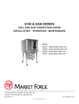
sterilmatic
digital ELECTRIC STERILIZER
PARTS and service manual
Effective june 12, 2015
Superseding All Previous Parts Lists.
The Company reserves the right to make substitution in the event that items specified are not available.
ERRORS: Descriptive and/or typographic errors are subject to correction.
MARKET FORGE INDUSTRIES
44 Lakeside Avenue, Burlington, Vermont 05401 USA Telephone: (802) 658-6600 Fax: (802) 860-3732
www.mfii.com
P/N 14-0414 Rev C
Table of Contents
DOOR ASSEMBLY & ADJUSTMENT. . . . . . . . . . . . . . . . . . . . . . . . . . . . . . . . . . . . . . . . . . . . . . . . . . . . . 3
fulcrum and drain assembly. . . . . . . . . . . . . . . . . . . . . . . . . . . . . . . . . . . . . . . . . . . . . . . . . . . . . . 5
miscellaneous components. . . . . . . . . . . . . . . . . . . . . . . . . . . . . . . . . . . . . . . . . . . . . . . . . . . . . . 6
troubleshooting.. . . . . . . . . . . . . . . . . . . . . . . . . . . . . . . . . . . . . . . . . . . . . . . . . . . . . . . . . . . . . . . . . . 7
error codes. . . . . . . . . . . . . . . . . . . . . . . . . . . . . . . . . . . . . . . . . . . . . . . . . . . . . . . . . . . . . . . . . . . . . . . . 8
illustrated parts list. . . . . . . . . . . . . . . . . . . . . . . . . . . . . . . . . . . . . . . . . . . . . . . . . . . . . . . . . . . . . 9
june 12, 2015
2
STM-Ed & STM-EDX sterilizers
DOOR ASSEMBLY & ADJUSTMENT
STERILMATIC DOOR ASSEMBLY
DOOR ADJUSTMENT
The Door of the Sterilmatic has been engineered to establish a positive method of sealing the steam pressure
within the sterilizing cylinder. As steam pressure builds
up within the cylinder, the door seal will tend to become
more positive.
The Door Adjustment is Located in the Fulcrum Casting
at the base of the door opening. This adjustment employs
the use of a screw and locknut in order to adjust the Sterilmatic Door to a tighter closed position (to prevent steam
from leaking by the door gasket as pressure builds up), it
is necessary to loosen the locknut and back off the screw
at least one-quarter of a turn and re-tighten the locknut.
However, the door should be adjusted to make a good
initial seal between the door gasket and the door opening
without the added assistance of internal cylinder steam
pressure with the simple action of securing the door handle down in a locked position, the door gasket should be
sufficiently compressed against the door opening, all the
way around to prevent any steam leakage from occurring.
Figure 2
Figure 1
THE DOOR GASKET
Keep the gasket clean. With normal closing and locking
of the door assembly, a steam-tight seal should be made
between the door gasket and the door opening. This seal
cannot be maintained if particles of foreign matter are allowed to accumulate upon either of the contacting surfaces.
If there is leakage by the door gasket before a steam
build-up within the steam chamber and leakage does not
stop when the sterilizer reaches sterilizing temperature
and pressure than regard the door assembly as improperly adjusted. A re-adjustment must then be made of the
seal adjustment door screw.
To change the door gasket, remove the entire door assembly as a unit. Discard the old gasket, replace it with
a new one (no cement is required), and reinstall the door
assembly. Make an operational check for leakage and adjust the door, if necessary.
june 12, 2015
3
STM-Ed & STM-EDX sterilizers
DOOR ASSEMBLY & ADJUSTMENT
1. First, lift off and remove the two pan supports to expose the door linkage on either side of the inner sterilizing chamber .
DOOR LIFT SPRING
Market Forge supplies door lift springs in sets only. This
policy has been found to be in the best interest of the
customer. Through continuous use, some of the original
qualities of the springs are lost and it becomes advantageous to make replacements to both the left and right
door lift springs in the event that one becomes damaged
or broken.
2. Raise the door to a fully opened position, and disengage the door spring from each of the door spring
studs. Accomplish this by counteracting the force of
the door lift spring with one hand while working the
end of the door spring off the spring stud with the free
hand. Do this on both sides of the door assembly.
Replacement door lift springs are marked with tabs at
the factory prior to shipment to identify a right from a left
spring. These springs must be installed with the right
door lift spring on the right of the door and the left door lift
spring on the left of the door as viewed from the front of
the sterilizer.
3. When the end of the door springs have been completely freed from their respective door spring studs,
the door springs on either side of the door assembly
can easily be slipped off their studs.
4. Rotate the entire door assembly out through the
door opening, passing the door handle through the
opening first, and then one end of the door spring as
shown in the illustration. The remainder of the door
assembly will then pass through the door opening
quite easily.
TO REMOVE THE DOOR ASSEMBLY
The Door Assembly can be removed from the inner sterilizing chamber as a unit without the use of any special
tools or equipment. However, a systematic approach to
this is warranted as the clearances through the portal are
close, and much confusion can result if not removed in
the sequence described below:
5. To replace the door assembly, reverse the step-bystep procedure described above.
Figure 3
item
part no.
1
10-6765
2
item
part no.
Pivot Spring Bearing
5
95-3204
Door & Door Spring Assembly
91-2718
Right and Left Door Spring (sold as a
pair)
-
95-0124
Items 1 through 5
3
10-1776
10-32 Machine Screw 1/2” Long
-
10-1937
Pan Support Stud
4
10-2666
Door Gasket
-
10-1939
Door Lift Spring Stud
june 12, 2015
description
4
description
STM-Ed & STM-EDX sterilizers
fulcrum and drain assembly
THE FULCRUM & DRAIN
ASSEMBLY
The fulcrum and drain assembly is located at the lower front
of the sterilizing chamber and
furnishes a sturdy anchorage
for the door locking system of
the door handle. Also provided
in this assembly is a means for
adjustment of the door seal. The
drain port and drain valve provide a means of discharging accumulations of water from within
the sterilizing chamber
ROLLER ASSEMBLY
(Items 8 & 9)
The Roller Assembly must be
kept free-rolling at all times.
Should this assembly be allowed
to become frozen due to lack of
lubrication, undue strain will be
put on the door handle and the
fulcrum casting while the door
is being locked. Use only a dry
lubricant such as graphite; as oil
or grease will tend to attract dirt
to this area.
Figure 4
item
part no.
1
10-3116
2
item
part no.
1/4” - 20 X 5/8 helicoil
13
10-4485
Drain valve knob
10-1999
10-32 Machine screw, 1 5/8” long
14
10-2514
#10 Shakeproof lockwasher
3
10-2358
1/4” - 20 fulcrum nut
15
10-2318
10-32 acorn nut
4
10-2087
1/4” - 20 allen set screw
16
95-2643
Adapter - steinball valve
5
10-3111
1/4” - 20x 3/8 helicoil
17
10-1950
6-32 Round head screw 1 5/8” long
6
10-2513
1/4” Shakeproof washer
18
95-2616
Front outer case lower
7
10-1763
1/4” - 20 Machine screw 3/4” long
19
95-0116
Fulcrum and drain casting
8
95-0120
Bearing spacer
20
10-1049
9
95-0198
Bronze Bearing
Nipple 1/2” IPS 2 1/4” long stainless
steel
10
10-3111
1/4” - 20 x 3/8 helicoil
21
10-1041
Ball valve stein
11
10-2513
1/4” Shakeproof washer
-
95-0115
Fulcrum and drain assembly, Items 1
through 12, 14, 15, and 19
12
10-1790
1/4” - 20 Cap screw 7/8” long
june 12, 2015
description
5
description
STM-Ed & STM-EDX sterilizers
miscellaneous components
CAST-IN HEATING ELEMENTS:
THE FLUE
Located under the sterilizing cylinder is a bank of (3) Ushaped heating elements. These elements are welded in
place in a protective aluminum shield. The elements cannot be removed, and in the unlikely event that one or all
fail, the complete cylinder must be replaced.
The Flue serves as a protective shield for the safety
valve, exhaust valve, and electrical components as well
as a mounting base for the control panel. The Flue cover
may be removed to allow more room for servicing the
control components.
THE LOW WATER CUT-OFF (MANUAL RESET):
THE EXHAUST SOLENOID VALVE
Fastened to a special mounting brace behind the front
panel, the Low Water Cut-Off acts to shut off the complete
unit, should the water run dry. The Low Water Cut Off is
factory set, to shut the unit off when the cylinder temperature rises between 380° and 440° Fahrenheit.
The exhaust solenoid is normally closed. It opens at the
start of heating cycle to allow cold air to escape the chamber. It closes when chamber temperature reaches 209°F
(98°C). It also opens during a FAST VENT cycle.
When the Sterilmatic is turned on without water or the
water has been evaporated away, the temperature of
the aluminum sterilizing cylinder will rise and by heat induction effect the Low Water Cut-Off. Its inner electrical
contacts will be forced open from heat expansion, thus
cutting off the flow of electric current to the heating elements. With the replacement of water into the cylinder
the cylinder temperature will drop and the contacts of the
Low Water Cut-Off can be again closed. The unit will only
restart after the manual button has been re-set.
THE SAFETY VALVE
The Safety Valve is factory set to automatically open and
exhaust excess steam from within the sterilizing cylinder,
thereby assuring that operating pressures remain within
safe limits. The lever action of the safety valve must be
free to operate unrestricted at all times. If the Safety Valve
should leak continually with a pressure build-up or should
it cause an interruption on a sterilizing cycle prematurely
(below 124° Centigrade on the temperature gauge), it
must be replaced.
Figure 5
june 12, 2015
6
STM-Ed & STM-EDX sterilizers
troubleshooting
TROUBLE
POSSIBLE CAUSE
Sterilizer fails to operate at all (no 1. Not installed correctly.
pressure build up).
CORRECTION
1. Check wire diagram for correct hook
up.
2. Blown fuse.
2. Replace fuse. If it blows, check that
source of electric supply is 60 amps.
3. Contactor burned out.
3. Replace.
4. Wiring is defective.
4. Check all wiring. Repair or replace.
Sterilizer operates, but fails to 1. Current not heating all of the elebuild up 15.5 PSI pressure.
ments.
1. Remove lower front panel and see if
the heating elements are working..
2. Exhaust valve fails to hold pressure at
15.5 PSI.
2. Replace exhaust valve.
3. Steam leaks around door.
3. Check for worn gasket or make door
adjustment.
4. Safety valve blows-off prematurely.
4. Replace safety valve.
Unit releases pressure before cy- 1. Low water cut-off has functioned precle has terminated on timer.
maturely.
1. Replace low water cut-off.
Left and/or right side(s) heating 1. Contactors of the temperature control
element(s) remain on during TIMswitch remains closed.
ING/STERILIZATION cycle.
1. Replace switches.
june 12, 2015
7
STM-Ed & STM-EDX sterilizers
error codes
Err 04
When an error occurs such as a Low Water condition, an
error number will be displayed on the Digital LCD Display.
Following is a list of the error numbers and their descriptions;
Thermistor probe over max temperature limit of 350°F
(177°C)
Err 05
Err 01
PCB ambient sensor senses temperature above limit of
115°F (46.1°C)
Factory calibration corrupted. Must perform factory calibration.
This would typically be done initially at the factory only
Err 06
Err 02
Low water warning. Water must be added then hit the RESET button.
User setup data corrupted, user setup will be reset to defaults on any key press
Err 03
Thermistors probe input open. This indicates one of three
conditions;
1. The user did not set a temperature before starting a
cycle
2. One or more probe wires are not connected
3. The probe has failed and should be replaced
Once the problem has been resolved any key press will
clear the error and stop the buzzer
june 12, 2015
8
STM-Ed & STM-EDX sterilizers
illustrated parts list
1
2
3
21
4
5
6
7
8
10
23
16
13
12
11
17
9
15
22
20
18
19
14
Vent Piping View
item
part no.
description
qty
1
10-0938
Exhaust Solenoid Valve, 220/240 Volts
1
2
95-3730
90° Street Elbow, Brass, ½” IPS, (reworked)
1
3
10-7942
Safety Valve, 17 lbs
1
4
14-0175
Heat Sink
1
5
10-2863
90° Street Elbow, Brass, 1/2” NPT
1
6
10-3327
1/2” IPS Plug, Square Head, Brass
1
7
95-6318
Compression Tube Fitting, 1/8” x 1/4”, Brass (Drilled out with #29 – 0.136” Bit)
1
8
14-0475
Temperature Probe (Not Shown)
1
9
15-7212
Hose, S/S, 9” Length
1
10
10-3945
Hose Clamp
2
11
95-6319
Compression Fitting, 1/8”-27 NPT, Brass (Drilled out orifice with 0.0625” bit)
1
12
10-7988
1/4 NPT- 1/8 FPT Bushing, Brass
1
13
10-3741
3/8 – 1/4 Hex Bushing
1
14
10-1054
3/8 IPS Elbow, Brass
2
15
10-1056
1/2 - 1/2 - 3/8, Tee, Brass
1
16
08-5007
1/2 - 1/8 NPT Reducer Bushing, Brass
1
17
10-3352
1/2” NPT Tee, Brass
1
*18
08-4999
1/4” NPT Plug, Brass
1
19
10-3644
3/8” IPS Plug, Square Head, Brass
1
20
10-1055
3/8 – 3/8 – 3/8 FPT Tee, Brass
1
21
95-3216
5/8” OD Copper Tubing, Soft, 9” Length
1
22
10-7987
3/8” IPS Close Nipple
1
23
10-1057
3/8” IPS Straight Union, Brass
1
* Reserved for secondary temperature probe used only for testing calibration of autoclave.
june 12, 2015
9
STM-Ed & STM-EDX sterilizers
illustrated parts list
2
1
7
Electrical Components, Open Top View, Rear
6
8
5
9
10
4
11
12
3
1
Electrical Components, Open Top View, Front
item
part no.
1
09-6484
Contactor, 240V, 75 Amp
1
2
14-0176
Solid State Relay, 50 Amp
1
3
14-0177
Contactor, 2 Pole
3
4
14-0174
Axial Fan, 230V
1
5
14-0149
Printer
1
6
14-0161
Controller Board
1
7
14-0472
Low Water LED
1
8
10-5990
Low Water Cutoff
1
9
14-0162
Power Switch
1
10
14-0181
Power Supply
1
11
14-0180
Fuse, Slo-Blo
1
12
14-0178
Fuse Holder
1
june 12, 2015
description
qty
10
STM-Ed & STM-EDX sterilizers
illustrated parts list
ITEM
june 12, 2015
ALL MODELS
DESCRIPTION
QTY.
PART NO.
1
1
95-6236
2
1
3
1
95-2650
Upper Case, Front
4
1
98-4371
Lower Case, Front w/cutout
1
95-2616
Lower Case, Front (old style w/o cutout)
5
1
10-6363
Insulation, Body
6
1
10-6365
Insulation, Back
7
1
10-6364
Insulation, Bottom
8
1
95-0465
Bottom Cover for Elements
9
1
95-2628
Cylinder, 208V - 240V (Shown with Door Assy.)
Flue Cover Assy.
Flue Outer Case Wrap
11
STM-Ed & STM-EDX sterilizers
illustrated parts list
ITEM
june 12, 2015
ALL MODELS
DESCRIPTION
QTY.
PART NO.
1
1
95-3196
Outside Case, Left Side
2
1
95-3195
Outside Case, Right Side
3
1
95-3194
Outside Case, Back
4
1
10-0226
Handle Bumper
5
1
95-3484
Terminal Box Cover
6
2
95-2545
Pan Rack, 1 Left & 1 Right
7
1
95-2637
Condensate Baffle, Upper
8
1
95-3207
Perforated Water (Splash) Baffle
9
4
95-3284
Wear Strip
12
STM-Ed & STM-EDX sterilizers
illustrated parts list
14
15
10
9
11
12
13
3
8
4
2
1
7
5
6
16
Door Handle Assembly
june 12, 2015
13
STM-Ed & STM-EDX sterilizers
illustrated parts list
door handle assembly
ITEM
PART NO.
DESCRIPTION
1
10-2318
10-32 Acorn Nut
2
10-2514
#10 Shakeproof Lockwasher
3
95-0571
10-32 Machine Screw 1 3/8” Lg.
4
95-0120
Bearing Spacer
5
95-0136
Door Lock Casting
6
10-2517
3/8” Shakeproof Lockwasher
7
10-0050
Door Lock Knob
8
95-0134
Door Handle Casting
9
10-2359
1/4”-20 Acorn Nut
10
95-0658
Door Handle Bearing Stud
11
95-0659
Door Handle Bearing Plate
12
10-2513
1/4” Shakeproof Lockwasher
13
10-1731
1/4”-20 Machine Screw 5/8” Lg.
14
95-0190
Door Lock Casting Assy. (Items 1 through 6)
15
95-0145
Door Lock Knob Assy. (Items 1 through 7)
16
95-0144
Complete Door Handle Assy. (Items 1 through 13)
17
95-0198
Handle Bushing (Not Shown)
june 12, 2015
14
STM-Ed & STM-EDX sterilizers