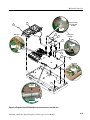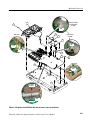
1
Service Manual
Tektronix 4000 Series
Digital Phosphor Oscilloscopes
071-2137--00
This document applies to firmware version 2.00
and above.
Warning
The servicing instructions are for use by qualified
personnel only. To avoid personal injury, do not
perform any servicing unless you are qualified to
do so. Refer to all safety summaries prior to
performing service.
www.tektronix.com
Copyright © Tektronix. All rights reserved. Licensed software products are owned by Tektronix or its subsidiaries or
suppliers, and are protected by national copyright laws and international treaty provisions.
Tektronix products are covered by U.S. and foreign patents, issued and pending. Information in this publication supercedes
that in all previously published material. Specifications and price change privileges reserved.
TEKTRONIX and TEK are registered trademarks of Tektronix, Inc.
TekLink is a trademark of Tektronix, Inc.
Tektronix is an authorized licensee of the CompactFlash® trademark.
Contacting Tektronix
Tektronix, Inc.
14200 SW Karl Braun Drive
P.O. Box 500
Beaverton, OR 97077
USA
For product information, sales, service, and technical support:
H In North America, call 1-800-833-9200.
H Worldwide, visit www.tektronix.com to find contacts in your area.
Table of Contents
General Safety Summary . . . . . . . . . . . . . . . . . . . . . . . . . . . . . . . . . . .
Service Safety Summary . . . . . . . . . . . . . . . . . . . . . . . . . . . . . . . . . . . .
Environmental Considerations . . . . . . . . . . . . . . . . . . . . . . . . . . . . . . .
Preface . . . . . . . . . . . . . . . . . . . . . . . . . . . . . . . . . . . . . . . . . . . . . . . . . . .
iii
v
vii
ix
Manual Conventions . . . . . . . . . . . . . . . . . . . . . . . . . . . . . . . . . . . . . . . . . . . . . .
Related Documentation . . . . . . . . . . . . . . . . . . . . . . . . . . . . . . . . . . . . . . . . . . .
ix
ix
Operating Information . . . . . . . . . . . . . . . . . . . . . . . . . . . . . . . . . . . . .
Theory of Operation . . . . . . . . . . . . . . . . . . . . . . . . . . . . . . . . . . . . . . .
1--1
2--1
Block Diagrams . . . . . . . . . . . . . . . . . . . . . . . . . . . . . . . . . . . . . . . . . . . . . . . . .
Power Supply . . . . . . . . . . . . . . . . . . . . . . . . . . . . . . . . . . . . . . . . . . . . . . . . . . .
I/O Board . . . . . . . . . . . . . . . . . . . . . . . . . . . . . . . . . . . . . . . . . . . . . . . . . . . . . .
Main Board . . . . . . . . . . . . . . . . . . . . . . . . . . . . . . . . . . . . . . . . . . . . . . . . . . . . .
Front-- Panel Board . . . . . . . . . . . . . . . . . . . . . . . . . . . . . . . . . . . . . . . . . . . . . . .
2-- 1
2-- 2
2-- 2
2-- 2
2-- 3
Adjustment Procedures . . . . . . . . . . . . . . . . . . . . . . . . . . . . . . . . . . . . .
3--1
Required Equipment . . . . . . . . . . . . . . . . . . . . . . . . . . . . . . . . . . . . . . . . . . . . . .
Overview of the Adjustment Process . . . . . . . . . . . . . . . . . . . . . . . . . . . . . . . . .
Factory Adjustment Procedure . . . . . . . . . . . . . . . . . . . . . . . . . . . . . . . . . . . . . .
Completing the Procedure . . . . . . . . . . . . . . . . . . . . . . . . . . . . . . . . . . . . . . . . .
3-- 1
3-- 2
3-- 4
3-- 8
Maintenance . . . . . . . . . . . . . . . . . . . . . . . . . . . . . . . . . . . . . . . . . . . . . .
4--1
Preventing ESD . . . . . . . . . . . . . . . . . . . . . . . . . . . . . . . . . . . . . . . . . . . . . . . . .
Inspection and Cleaning . . . . . . . . . . . . . . . . . . . . . . . . . . . . . . . . . . . . . . . . . . .
General Care . . . . . . . . . . . . . . . . . . . . . . . . . . . . . . . . . . . . . . . . . . . . . . . .
Interior Cleaning . . . . . . . . . . . . . . . . . . . . . . . . . . . . . . . . . . . . . . . . . . . . .
Exterior Cleaning . . . . . . . . . . . . . . . . . . . . . . . . . . . . . . . . . . . . . . . . . . . .
Overview of Removal Procedures . . . . . . . . . . . . . . . . . . . . . . . . . . . . . . . . . . .
Removal Procedures . . . . . . . . . . . . . . . . . . . . . . . . . . . . . . . . . . . . . . . . . . . . . .
Troubleshooting . . . . . . . . . . . . . . . . . . . . . . . . . . . . . . . . . . . . . . . . . . . . . . . . .
Troubleshooting Procedure . . . . . . . . . . . . . . . . . . . . . . . . . . . . . . . . . . . . . . . . .
Unpacking and Repacking Instructions . . . . . . . . . . . . . . . . . . . . . . . . . . . . . . .
4-- 1
4-- 1
4-- 2
4-- 2
4-- 2
4-- 6
4-- 8
4-- 12
4-- 13
4-- 16
Mechanical Parts List . . . . . . . . . . . . . . . . . . . . . . . . . . . . . . . . . . . . . .
5--1
Parts Ordering Information . . . . . . . . . . . . . . . . . . . . . . . . . . . . . . . . . . . . . . . . .
Using the Replaceable Parts List . . . . . . . . . . . . . . . . . . . . . . . . . . . . . . . . . . . .
5-- 1
5-- 2
Tektronix 4000 Series Digital Phosphor Oscilloscopes Service Manual
i
Table of Contents
List of Tables
Table 4--1: External inspection check list . . . . . . . . . . . . . . . . . . . . . .
Table 4--2: Internal inspection check list . . . . . . . . . . . . . . . . . . . . . .
4--3
4--4
Figure 2--1: Oscilloscope module interconnections . . . . . . . . . . . . . . .
Figure 3--1: Rear panel . . . . . . . . . . . . . . . . . . . . . . . . . . . . . . . . . . . . .
Figure 3--2: Utility page menu . . . . . . . . . . . . . . . . . . . . . . . . . . . . . . .
Figure 3--3: Calibration selection . . . . . . . . . . . . . . . . . . . . . . . . . . . . .
Figure 3--4: Factory information dialog . . . . . . . . . . . . . . . . . . . . . . .
Figure 3--5: Digital channel input . . . . . . . . . . . . . . . . . . . . . . . . . . . .
Figure 4--1: Locator for trim and cabinet removal . . . . . . . . . . . . . . .
Figure 4--2: Locator for internal modules . . . . . . . . . . . . . . . . . . . . . .
Figure 4--3: Primary troubleshooting procedure . . . . . . . . . . . . . . . .
Figure 4--4: AC power supply troubleshooting procedure . . . . . . . . .
Figure 4--5: Module isolation troubleshooting procedure . . . . . . . . .
Figure 5--1: Exploded view, case . . . . . . . . . . . . . . . . . . . . . . . . . . . . . .
Figure 5--2: Exploded view: DPO4000 front panel and display,
4-channel instruments . . . . . . . . . . . . . . . . . . . . . . . . . . . . . . . . . . .
Figure 5--3: Exploded view: MSO4000 front panel and display,
4-channel instruments . . . . . . . . . . . . . . . . . . . . . . . . . . . . . . . . . . .
Figure 5--4: Exploded view: DPO4000 front panel and display,
2-channel instruments . . . . . . . . . . . . . . . . . . . . . . . . . . . . . . . . . . .
Figure 5--5: Exploded view: MSO4000 front panel and display,
2-channel instruments . . . . . . . . . . . . . . . . . . . . . . . . . . . . . . . . . . .
Figure 5--6: Exploded view: DPO4000 Power Supply
and I/O board . . . . . . . . . . . . . . . . . . . . . . . . . . . . . . . . . . . . . . . . .
Figure 5--7: Exploded view: MSO4000 Power Supply
and I/O board . . . . . . . . . . . . . . . . . . . . . . . . . . . . . . . . . . . . . . . . .
Figure 5--8: Exploded view: DPO4000 Main board,
Inverter board, and side fans . . . . . . . . . . . . . . . . . . . . . . . . . . . . .
Figure 5--9: Exploded view: MSO4000 Main board,
Inverter board, and side fans . . . . . . . . . . . . . . . . . . . . . . . . . . . . .
2--1
3--4
3--5
3--6
3--6
3--10
4--7
4--8
4--13
4--14
4--15
5--5
List of Figures
ii
5--7
5--9
5--11
5--13
5--15
5--17
5--19
5--21
Tektronix 4000 Series Digital Phosphor Oscilloscopes Service Manual
General Safety Summary
Review the following safety precautions to avoid injury and prevent damage to
this product or any products connected to it.
To avoid potential hazards, use this product only as specified.
Only qualified personnel should perform service procedures.
To Avoid Fire or
Personal Injury
Use Proper Power Cord. Use only the power cord specified for this product and
certified for the country of use.
Connect and Disconnect Properly. Do not connect or disconnect probes or test
leads while they are connected to a voltage source.
Ground the Product. This product is grounded through the grounding conductor
of the power cord. To avoid electric shock, the grounding conductor must be
connected to earth ground. Before making connections to the input or output
terminals of the product, ensure that the product is properly grounded.
Observe All Terminal Ratings. To avoid fire or shock hazard, observe all ratings
and markings on the product. Consult the product manual for further ratings
information before making connections to the product.
The inputs are not rated for connection to mains or Category II, III, or IV
circuits.
Connect the probe reference lead to earth ground only.
Do not apply a potential to any terminal, including the common terminal, that
exceeds the maximum rating of that terminal.
Do Not Operate Without Covers. Do not operate this product with covers or panels
removed.
Do Not Operate With Suspected Failures. If you suspect there is damage to this
product, have it inspected by qualified service personnel.
Avoid Exposed Circuitry. Do not touch exposed connections and components
when power is present.
Do Not Operate in Wet/Damp Conditions.
Do Not Operate in an Explosive Atmosphere.
Keep Product Surfaces Clean and Dry.
Provide Proper Ventilation. Refer to the manual’s installation instructions for
details on installing the product so it has proper ventilation.
Tektronix 4000 Series Digital Phosphor Oscilloscopes Service Manual
iii
General Safety Summary
Terms in this Manual
These terms may appear in this manual:
WARNING. Warning statements identify conditions or practices that could result
in injury or loss of life.
CAUTION. Caution statements identify conditions or practices that could result in
damage to this product or other property.
Symbols and Terms
on the Product
These terms may appear on the product:
H
DANGER indicates an injury hazard immediately accessible as you read the
marking.
H
WARNING indicates an injury hazard not immediately accessible as you
read the marking.
H
CAUTION indicates a hazard to property including the product.
The following symbols may appear on the product:
CAUTION
Refer to Manual
Protective Ground
(Earth) Terminal
Chassis Ground
Mains Connected
ON (Power)
Push button OUT
Push button
IN
iv
Tektronix 4000 Series Digital Phosphor Oscilloscopes Service Manual
Service Safety Summary
Only qualified personnel should perform service procedures. Read this Service
Safety Summary and the General Safety Summary before performing any service
procedures.
Do Not Service Alone. Do not perform internal service or adjustments of this
product unless another person capable of rendering first aid and resuscitation is
present.
Disconnect Power. To avoid electric shock, switch off the instrument power, then
disconnect the power cord from the mains power.
Use Care When Servicing With Power On. Dangerous voltages or currents may
exist in this product. Disconnect power, remove battery (if applicable), and
disconnect test leads before removing protective panels, soldering, or replacing
components.
To avoid electric shock, do not touch exposed connections.
Tektronix 4000 Series Digital Phosphor Oscilloscopes Service Manual
v
Service Safety Summary
vi
Tektronix 4000 Series Digital Phosphor Oscilloscopes Service Manual
Environmental Considerations
This section provides information about the environmental impact of the
product.
Product End-of-Life
Handling
Observe the following guidelines when recycling an instrument or component:
Equipment Recycling. Production of this equipment required the extraction and
use of natural resources. The equipment may contain substances that could be
harmful to the environment or human health if improperly handled at the
product’s end of life. In order to avoid release of such substances into the
environment and to reduce the use of natural resources, we encourage you to
recycle this product in an appropriate system that will ensure that most of the
materials are reused or recycled appropriately.
The symbol shown to the left indicates that this product
complies with the European Union’s requirements
according to Directive 2002/96/EC on waste electrical and
electronic equipment (WEEE). For information about
recycling options, check the Support/Service section of the
Tektronix Web site (www.tektronix.com).
Mercury Notification. This product uses an LCD backlight lamp that contains
mercury. Disposal may be regulated due to environmental considerations. Please
contact your local authorities or, within the United States, the Electronics
Industries Alliance (www.eiae.org) for disposal or recycling information.
Restriction of Hazardous
Substances
This product has been classified as Monitoring and Control equipment, and is
outside the scope of the 2002/95/EC RoHS Directive. This product is known to
contain lead, cadmium, mercury, and hexavalent chromium.
Tektronix 4000 Series Digital Phosphor Oscilloscopes Service Manual
vii
Environmental Considerations
viii
Tektronix 4000 Series Digital Phosphor Oscilloscopes Service Manual
Preface
This service manual provides information that you need to troubleshoot,
disassemble, and replace parts on the Tektronix 4000 Series Digital Phosphor
Oscilloscopes.
Manual Conventions
This manual uses certain conventions that you should become familiar with
before attempting service.
Modules
Throughout this manual, any replaceable component, assembly, or part is
referred to by the term module. A module is composed of electrical and
mechanical assemblies, circuit boards, interconnecting cables, and
user-accessible controls.
Replaceable Parts
This manual refers to any field-replaceable assembly or mechanical part
specifically by its name or generically as a replaceable part. In general, a
replaceable part is any circuit board or assembly, such as the hard disk drive, or a
mechanical part, such as the I/O port connectors, that is listed in the replaceable
parts list.
Safety
Symbols and terms related to safety appear in the General Safety Summary found
at the beginning of this manual.
Related Documentation
To read about
Use these documents
Installation and Operation
Tektronix 4000 Series Digital Phosphor Oscilloscopes User
Manual (available in 11 languages)
Specifications and Performance Tektronix 4000 Series Technical Reference (PDF only)
Programmer Commands
Tektronix 4000 Series Programmer Manual (PDF only)
Analysis and Connectivity Tools Getting Started with OpenChoice® Solutions Manual
Tektronix 4000 Series Digital Phosphor Oscilloscopes Service Manual
ix
Preface
To read about
Use these documents
Installing and testing applications modules
Tektronix 4000 Series Application Modules Installation
Instructions Manual
Oscilloscope calibrator
Fluke Oscilloscope Calibrator Manual at
http://us.fluke.com
x
Tektronix 4000 Series Digital Phosphor Oscilloscopes Service Manual
Operating Information
Operating Information
For information on installing and operating your DPO4000 or your MSO4000
Series Digital Phosphor Oscilloscope, refer to the Tektronix 4000 Series Digital
Phosphor Oscilloscopes User Manual.
This manual is available, in 11 languages, on the Web at www.tektronix.com.
Tektronix 4000 Series Digital Phosphor Oscilloscopes Service Manual
1- 1
Operating Information
1- 2
Tektronix 4000 Series Digital Phosphor Oscilloscopes Service Manual
Theory of Operation
Theory of Operation
This chapter describes the electrical operation of the oscilloscope to the module
level. Figure 2--1 shows the oscilloscope module interconnections.
Block Diagrams
AC Line
Power
Supply
CompactFlash
Port
XGA
Video
port
Trigger
Out
J140
J170
J100
Display
back light
inverter
power
LCD
Display
J680
J930
Front Panel
I/O Board
J440
J0480
J610
J1
J420, J421
Input ports for
application
modules
Main board
J120
J130
USB
J510
3 Fans
J570
J571
J850
Bezel
buttons
Attenuator circuit
Ethernet
port
Ch 1
Ch 2
Ch 1
Ch 2
Ch 3
Ch 4
Aux in 4-channel oscilloscopes
Aux in 2-channel oscilloscopes
Figure 2- 1: Oscilloscope module interconnections
Tektronix 4000 Series Digital Phosphor Oscilloscopes Service Manual
2- 1
Theory of Operation
Power Supply
The Power Supply board converts AC line voltage to +12 V to power for all
internal circuits.
I/O Board
The I/O board contains USB ports, a CompactFlash port, an Ethernet port
(LAN), an XGA Video port, and a Trigger Out BNC connector.
Main Board
The Main board module contains the following functions:
2- 2
Acquisition System
The Acquisition system begins with the analog signal path and ends with a
digitized signal in memory. The signal enters a channel input, and then passes
through an attenuator and preamplifier. The analog signal from each preamplifier
goes through a digitizer, a time base controller, and then into acquisition
memory. The analog signal from each preamplifier is also distributed to a trigger
circuit.
Trigger System
The Trigger system processes the analog signals from the preamplifiers and
sends trigger information to the time--base controller. Advanced trigger functions
are enabled only when the appropriate application modules and supporting
software are installed.
Display System
The Display system combines live waveform data from acquisition memory with
menus and text, and stores this information in display memory. It then uses this
data to refresh the XGA display module (LCD).
Tektronix 4000 Series Digital Phosphor Oscilloscopes Service Manual
Theory of Operation
Processor System
The Processor system contains a 440EP Power PC microprocessor that controls
the entire instrument. The processor system also contains FLASH ROM, system
RAM, and interfaces to USB ports and a CompactFlash port.
Power Converter
The Power Converter receives +12 V from the main power supply and generates
voltages for the analog and digital circuitry on the Main board.
Front- Panel Board
The Front Panel board contains a microprocessor that reads the front-panel
buttons and controls, and then sends this information to the processor system on
the Main board. The Front Panel board also generates the probe compensation
output signal and provides an interface to the application modules.
Tektronix 4000 Series Digital Phosphor Oscilloscopes Service Manual
2- 3
Theory of Operation
2- 4
Tektronix 4000 Series Digital Phosphor Oscilloscopes Service Manual
Adjustment Procedures
Adjustment Procedures
This chapter contains the factory adjustment procedure for the DPO4000 Series
and the MSO4000 Series oscilloscopes. Only qualified personnel should perform
adjustment procedures. Read the Service Safety Summary and the General Safety
Summary before performing any service procedures.
NOTE. The voltage references inside the oscilloscope are very stable over time
and should not require routine adjustment. Before performing any procedure in
this chapter, do the Performance Verification procedures to check whether the
oscilloscope meets specifications. See the Tektronix 4000 Series Technical
Reference documentation.
Successful completion of this adjustment procedure automatically updates the
stored time and date of the latest successful adjustment. Completion of the
Performance Verification procedure does not update this date and time. If no
adjustment is needed, there is also no need to update the time and date of the
adjustment.
Required Equipment
The following equipment, or a suitable equivalent, is required to complete these
procedures.
The following table specifies required equipment for the MSO4000 Series
oscilloscope.
Description
Minimum requirements
Example
DC voltage source
50 mV to 70 V, ±0.1% amplitude
accuracy
Fluke or Wavetek 9500
Oscilloscope Calibrator with
five 9530 active heads.
Digital calibrator probe
Tektronix 4000 Series Digital Phosphor Oscilloscopes Service Manual
Tektronix part number:
174-- 4535-- XX
3- 1
Adjustment Procedures
The following table specifies required equipment for the DPO4000 Series
oscilloscope.
Description
Minimum requirements
Example
DC voltage source
50 mV to 70 V, ±0.1% amplitude
accuracy
Fluke or Wavetek 9500
Oscilloscope Calibrator with
9530 active heads
Sine Generator
1kHz1 GHz
Edge Generator
1 kHz with < 50 ps ch-- ch skew
Wavetek 9500 Oscilloscope
Calibrator with one 9510
Output Module
50 Ω BNC cable
BNC male to BNC male, about
10 in (25 cm) long
Tektronix part number
012-- 0208-- 00
Adjustment tool
Non-- conducting shaft with
diameter = 0.1 in (= 2.5 mm)
Tektronix part number
003-- 1433-- 00
Overview of the Adjustment Process
Before performing adjustment procedures, you must warm up the oscilloscope
for at least 30 minutes in an ambient temperature between 20 °C and 30 °C.
Adjustments performed before warm-up or outside this temperature range may
result in poor performance or calibration failure.
The factory adjustment procedure consists of a series of steps; as you move
through these steps, the oscilloscope display provides instructions that describe
the specific input signal requirements for each step. If the oscilloscope passes the
step, it moves on to the next step. If the oscilloscope fails, you can repeat the
step or choose to abort the procedure.
If you have difficulty completing the steps, refer to the Completing the
Procedure section for specific instructions and troubleshooting information.
To complete the calibration procedure, you must know how to operate the
oscilloscope calibrator. Please refer to the user manual, which can be found at
http://us.fluke.com.
3- 2
Tektronix 4000 Series Digital Phosphor Oscilloscopes Service Manual
Adjustment Procedures
NOTE. Do not turn any knobs or push any front-panel buttons other than the
Next Step or Previous Step buttons during the adjustment procedure. Doing so
will cause the oscilloscope to abort the adjustment procedure. The oscilloscope
uses the previous calibration constants if the adjustment procedure is aborted or
fails.
The screen does not display the actual oscilloscope settings (such as channel
input impedance, or vertical and horizontal settings) during the adjustment
procedure. The oscilloscope automatically sets the instrument settings, but these
settings may not read out correctly on the display.
During some steps, the instrument may appear to be idle for several minutes
while it is processing information internally.
If the oscilloscope completes all steps in the procedure successfully, a “Pass”
message is displayed and the new calibration constants take effect. If the
oscilloscope does not pass a step, you can repeat the step. To cancel the
calibration procedure, press the Menu Off front panel button on the oscilloscope.
This reverts the oscilloscope to the old calibration constants.
Tektronix 4000 Series Digital Phosphor Oscilloscopes Service Manual
3- 3
Adjustment Procedures
Factory Adjustment Procedure
To perform the factory adjustment procedure, complete these steps:
1. Connect the oscilloscope to an AC power source.
NOTE. You must connect the oscilloscope and the test equipment to the same AC
power circuit. Connect the oscilloscope and test instruments to a common power
strip if you are unsure of the AC power circuit distribution. Connecting the
oscilloscope and test instruments to separate AC power circuits can result in
offset voltages between the equipment, which can invalidate the adjustment
procedure.
2. Power on the oscilloscope and warm it up for 30 minutes.
3. Power on the oscilloscope calibrator and warm it up for 30 minutes.
4. Connect the active heads from the calibrator to the oscilloscope, ensuring
that Channel 1 on the calibrator connects to Channel 1 on the oscilloscope,
and so on.
NOTE. For the DPO4000, there will be either 2 or 4 channels to connect. For the
MSO4000, there will be either 2 or 4 channels to connect, plus an additional
channel connection for the digital probe. Plug the digital probe into the
Channel 5 active head on the calibrator, but do not plug the probe into the
oscilloscope until you begin a Deskew test.
5. Power off the oscilloscope. Locate the hole in the rear panel that provides
access to the CAL switch, as shown in Figure 3--1.
CAL
Figure 3- 1: Rear panel
3- 4
Tektronix 4000 Series Digital Phosphor Oscilloscopes Service Manual
Adjustment Procedures
6. Insert the adjustment tool into the CAL switch hole. Use the tool to push and
hold the CAL switch in while you power on the oscilloscope. Keep holding
the switch until the oscilloscope shows the “Power-on self--test passed”
message with the oscilloscope graticule in the background. This can take up
to a minute.
7. Push the Default Setup button on the front panel of the oscilloscope.
8. Push the Utility button on the front panel of the oscilloscope.
9. Push the Utility Page lower--bezel button. The utility page menu appears, as
shown in Figure 3--2.
Figure 3- 2: Utility page menu
10. Use the Multipurpose a knob to select Calibration, as shown in
Figure 3--3.
Tektronix 4000 Series Digital Phosphor Oscilloscopes Service Manual
3- 5
Adjustment Procedures
Figure 3- 3: Calibration selection
11. Push the Factory lower--bezel button. The information dialog appears, as
shown in Figure 3--4.
Figure 3- 4: Factory information dialog
3- 6
Tektronix 4000 Series Digital Phosphor Oscilloscopes Service Manual
Adjustment Procedures
12. Push the OK Do Factory Calibration side--bezel button, as shown in
Figure 3--4, to start the adjustment process. Prompts appear on the oscilloscope screen to indicate the signal type and the channels to which it should
be connected.
NOTE. The oscilloscope adjusts itself automatically using the calibrator signal
as a reference. You do not need to make any adjustments.
If you make an error, such as connecting the wrong input signal, you can repeat
the last step by pushing the Return to Previous Screen side bezel button.
13. For each step, refer to the next table to identify the signal type, and then
carefully follow the instructions for that signal type on the specified page.
Signal type
Example prompt
Refer to
Parameters to set
DC Voltage
Apply 0 V DC 50 Ω termination signal to 3.
Page 3-- 8
Waveform type, voltage,
termination, channel
Time Mark
Apply 500 mV Pk-- Pk 625 Page 3-- 9
Hz 50 Ω termination
time mark signal to 3.
Waveform type, voltage,
frequency, termination,
channel
Deskew
Apply 1.0 V Pk-- Pk 1 kHz Page 3-- 10
50 Ω termination deskew
signal to 3.
Waveform type, voltage,
frequency, termination,
channel
Sine Signal
Apply 2.0 V Pk-- Pk 164M
50 Ω termination sine
signal to 3.
Waveform type, voltage,
frequency, termination,
channel
Page 3-- 11
NOTE. The oscilloscope screen will not provide you with all of the information
that you need to complete the steps successfully, so it is critical that you follow
the steps outlined in the Completing the Procedure section. Each time a new
prompt appears, refer to the table above to identify the signal type, and then
ensure that you are following every step that is outlined for that specific signal
type.
14. Continue with the adjustment process until it is complete and you receive the
Pass notification. You can cancel the process at any time by pushing the
MENU OFF button.
15. Complete the performance verification tests to verify that the adjustment
procedure has correctly calibrated the oscilloscope. (See the Tektronix 4000
Series Technical Reference.) Incorrect use of calibration equipment can cause
the oscilloscope to pass the Calibration Procedure but fail Performance
Verification.
Tektronix 4000 Series Digital Phosphor Oscilloscopes Service Manual
3- 7
Adjustment Procedures
Completing the Procedure
Instructions for completing the DC Voltage, Time Mark, Deskew and Sine Signal
tests are below. For each step in the calibration procedure, start at the beginning
of the numbered instructions for the specific test type, and carefully complete
each step.
If the oscilloscope fails a step, consult the Troubleshooting section at the end of
this chapter, revert to the previous step and try again. If the step fails again,
return to the first step in the calibration procedure and try the entire procedure
again. If the procedure fails, there could be problem with the oscilloscope.
Consider seeking customer support.
DC Voltage
The DC Voltage test is the first test to appear on the prompts, and it usually
makes up the majority of the calibration procedure tests. For each DC Voltage
test, complete all 8 steps listed below to best ensure that the test will pass.
1. Push the DC/Square
button.
2. Push the WAVEFORM lower--bezel button, and then push the DC Positive
right--bezel button.
3. Push the CHANNEL SELECT lower--bezel button.
4. Push the LOAD lower--bezel button to highlight either 1M Ω or 50 M Ω.
5. Select the specified channels, by using the side--bezel buttons, and then click
the EXIT lower--bezel button.
6. If the amplitude field is not selected, use the front panel scroll buttons. Type
the specified voltage, and then push the appropriate unit in the right--bezel
menu.
H
lower-For 0 V: ground the signal by pushing the grounding
bezel button. When this is active, you will not be able to make a channel
selection, so in some cases you might need to temporarily deselect the
grounding option while you make a channel selection. If the prompt
requires all channels and the signal is grounded, The calibrator screen
will default to Channel 1.
H
For any non--zero voltage: Before you select the voltage, you must first
ensure that the calibrator is in direct mode. Push the
button until 1.0 is selected.
H
1 2
1.Ø
5
lower--bezel
For 6 V or --6 V:
a. Push the AUX front panel button.
3- 8
Tektronix 4000 Series Digital Phosphor Oscilloscopes Service Manual
Adjustment Procedures
b. Push the
side--bezel button for a 6 V signal or push the
side--bezel button for a --6 V signal. The polarity will be
indicated only by the icon that appears in the upper--left corner of the
calibrator screen.
c. Set the amplitude to either 6 V or --6 V.
d. Set the Pulse/Energy setting to 7.2 Joules (the time should show
10s).
e. When all of the parameters are set and you ensure that the output is
ON, push the Trig Pulse side--bezel and IMMEDIATELY push the
OK Do Next Step side--bezel button on the oscilloscope. WARNING Once you push the Trig Pulse button on the calibrator, you
have only 9 seconds to push the OK Do Next Step button on the
oscilloscope. If the instrument fails one of these tests, go all the way
back to the first 6 V test (6 V on channel 1) and start that sequence
over again.
7. Ensure that the red light is illuminated to indicate that the output is on. If
not, push the ON button, as shown below:
8. On the oscilloscope, push the OK Do Next Step side--bezel button.
Time Mark
The Time Mark test is often the second test type to appear in the prompts. When
you receive a time mark prompt, complete the following steps:
1. Push the Markers
front--panel button.
2. Push the WAVEFORM lower--bezel button, and then push the
side--bezel button.
NOTE. If a 625 Hz signal is required, set the time marker to 1.6 ms.
Tektronix 4000 Series Digital Phosphor Oscilloscopes Service Manual
3- 9
Adjustment Procedures
3. Select the Amplitude field using the front panel scroll buttons, and then
change the voltage by using the large front panel knob on the calibrator.
4. Ensure that the red light is illuminated to indicate that the output is on. If
not, push the ON button.
5. On the oscilloscope, push the OK Do Next Step right--bezel button.
Deskew (MSO Only)
If you are using the MSO4000 Series oscilloscope, and you recieve a prompt for
a deskew test, complete the following steps:
1. Plug the probe, notch down, into the digital channel input, as shown in
Figure 3--5. Ensure that is snaps into place. Keep the probe plugged in for
the remainder of the calibration procedure.
Measure
Search
Test
Cursors
Select
Fine
Acquire
Intensity
Run / Stop
Single
Set / Clear
Autoset
M
Menu
R
B1
B2
B3
Menu
Off
1
2
3
4
Set to 50%
ForceTrig
B4
D15 - D0
CompactFlashٛ
Save
Menu
Default
Setup
Utility
Figure 3- 5: Digital channel input
2. Push the Aux front--panel button, and then push the Zero skew
side--bezel button.
3. Set the specified voltage, frequency, and termination.
4. Push the CHANNEL SELECT button and ensure that all channels are
selected, including Channel 5.
5. Ensure that the red light is illuminated to indicate that the output is on. If
not, push the ON button.
6. On the oscilloscope, push the OK Do Next Step right--bezel button. In some
cases, this can take several minutes.
3- 10
Tektronix 4000 Series Digital Phosphor Oscilloscopes Service Manual
Adjustment Procedures
CAUTION. Keep the digital probe plugged in to the oscilloscope. Unplugging the
probe may result in aborting the test.
Sine Signal
When a Sine Signal prompt appears, complete the following steps:
1. Push the Sine
front panel button.
2. To ensure that the voltage is in direct mode, push the
button and select 1.0.
1 2
5
1.Ø
lower--bezel
3. Push the CHANNEL SELECT lower--bezel button, and then ensure that
Channel 5 is selected.
4. Ensure that the red light is illuminated to indicate that the output is on. If
not, push the ON button.
5. On the oscilloscope, push the OK Do Next Step right--bezel button.
Troubleshooting
Refer to the next table for common issues encountered during the calibration
procedure.
Problem
Things to try
The instrument fails a test
Are the channels hooked up properly, routed to the right
channels, and turned on?
Is the signal set to the correct waveform, frequency, and
termination (if applicable to the test)?
Is the output set to ON (the red light will be illuminated)?
If you make a correction or find that everything appears to be
correct, click the Go back a step button to try the test again.
I can’t set the amplitude to 0 V,
as specified in the prompt
Ground the signal by pushing the
button.
I can’t find the parameters that I
need to set
Is the waveform set correctly?
lower-- bezel
Is the grounding button on? When this is active, you will not
be able to make a channel selection, so in some cases you
might need to temporarily deselect the grounding option
while you make a channel selection.
If you can find the termination settings, click the CHANNEL
SELECT lower-- bezel button.
I can’t set the voltage to 625 Hz
Set the time marker to 1.6 Ms. This will automatically set the
voltage to 625 Hz.
I can’t set the signal to all
channels
If you are unable to set the signal to all channels, try setting
the signal to Channel 1.
Tektronix 4000 Series Digital Phosphor Oscilloscopes Service Manual
3- 11
Adjustment Procedures
Problem
Things to try
I’m having trouble with tests that Follow the steps for 6 V and - 6 V that appear in Step 6 of
require 6 V or - 6 V
the DC Voltage test.
Ensure that the polarity is correct, by referring to the icon
that appears in the upper-- left corner of the calibrator screen.
If the instrument fails a test, go all the way back to the first 6
V test (6 V on Channel 1) and start the sequence over again.
The Sine Signal test failed
3- 12
If the prompt specified Channel 4, try setting the signal to
Channel 5, instead.
Tektronix 4000 Series Digital Phosphor Oscilloscopes Service Manual
Maintenance
Maintenance
This section contains the information needed to do periodic and corrective
maintenance on the oscilloscrope, as well as repackaging instructions if you need
to return the oscilloscope to Tektronix for service.
Preventing ESD
Before servicing this product, read the Safety Summary and Introduction at the
front of the manual and the electrostatic discharge (ESD) information below.
CAUTION. Static discharge can damage any semiconductor component in this
oscilloscope
When performing any service that requires internal access to the oscilloscope,
adhere to the following precautions to avoid damaging internal modules and their
components due to electrostatic discharge.
1. Minimize handling of static-sensitive circuit boards and components.
2. Transport and store static-sensitive modules in their static protected
containers or on a metal rail. Label any package that contains static-sensitive
boards.
3. Discharge the static voltage from your body by wearing a grounded antistatic
wrist strap while handling these modules. Service static-sensitive modules
only at a static-free work station.
4. Do not place anything capable of generating or holding a static charge on the
work station surface.
5. Handle circuit boards by the edges when possible.
6. Do not slide the circuit boards over any surface.
7. Avoid handling circuit boards in areas that have a floor or work-surface
covering capable of generating a static charge.
Inspection and Cleaning
Inspection and cleaning are done as preventive maintenance. Preventive
maintenance, when done regularly, may prevent oscilloscope malfunction and
enhance its reliability.
Tektronix 4000 Series Digital Phosphor Oscilloscopes Service Manual
4- 1
Maintenance
Preventive maintenance consists of visually inspecting and cleaning the
oscilloscope and using general care when operating it.
How often you do maintenance depends on the severity of the environment in
which the oscilloscope is used. A proper time to perform preventive maintenance
is just before oscilloscope adjustment.
General Care
Flat Panel Display
Cleaning
The cabinet helps keep dust out of the oscilloscope and should normally be in
place when operating the oscilloscope.
The display is a soft plastic display and must be treated with care during
cleaning.
CAUTION. Improper cleaning agents or methods can damage the flat panel
display.
Avoid using abrasive cleaners or commercial glass cleaners to clean the display
surface.
Avoid spraying liquids directly on the display surface.
Avoid scrubbing the display with excessive force.
Clean the flat panel display surface by gently rubbing the display with a
clean-room wipe (such as Wypall Medium Duty Wipes, #05701, available from
Kimberly-Clark Corporation).
Interior Cleaning
Use a dry, low-velocity stream of air to clean the interior of the chassis. Use a
soft-bristle, non-static-producing brush for cleaning around components. If you
must use a liquid for minor interior cleaning, use a 75% isopropyl alcohol
solution and rinse with deionized water.
WARNING. To avoid injury, power down the instrument and disconnect it from
line voltage before performing any procedure that follows.
Exterior Cleaning
4- 2
Clean the exterior surfaces of the chassis with a dry lint-free cloth or a softbristle brush. If any dirt remains, use a cloth or swab dipped in a 75% isopropyl
alcohol solution. Use a swab to clean narrow spaces around controls and
connectors. Do not use abrasive compounds on any part of the chassis that may
damage the chassis.
Tektronix 4000 Series Digital Phosphor Oscilloscopes Service Manual
Maintenance
Clean the On/Standby switch using a dampened cleaning towel. Do not spray or
wet the switch directly.
CAUTION. Avoid the use of chemical cleaning agents, which might damage the
plastics used in this oscilloscope. Use only deionized water when cleaning the
menu buttons or front-panel buttons. Use a 75% isopropyl alcohol solution as a
cleaner and rinse with deionized water. Before using any other type of cleaner,
consult your Tektronix Service Center or representative.
Lubrication. There is no periodic lubrication required for this oscilloscope.
Exterior Inspection
Inspect the outside of the oscilloscope for damage, wear, and missing parts,
using Table 4--1 as a guide. Immediately repair defects that could cause personal
injury or lead to further damage to the oscilloscope.
Table 4- 1: External inspection check list
Item
Inspect for
Repair action
Cabinet, front panel,
and cover
Cracks, scratches, deformations,
damaged hardware.
Repair or replace defective
module.
Front-panel knobs
Missing, damaged, or loose
knobs.
Repair or replace missing or
defective knobs.
Connectors
Broken shells, cracked insulation, Repair or replace defective
and deformed contacts. Dirt in
modules. Clear or wash out dirt.
connectors.
Carrying handle, and
cabinet feet
Correct operation.
Repair or replace defective
module.
Accessories
Missing items or parts of items,
bent pins, broken or frayed
cables, and damaged
connectors.
Repair or replace damaged or
missing items, frayed cables, and
defective modules.
If the display is very dirty, moisten the wipe with distilled water or a 75%
isopropyl alcohol solution and gently rub the display surface. Avoid using excess
force or you may damage the plastic display surface.
CAUTION. To prevent getting moisture inside the oscilloscope during external
cleaning, use only enough liquid to dampen the cloth or applicator.
Tektronix 4000 Series Digital Phosphor Oscilloscopes Service Manual
4- 3
Maintenance
Interior Inspection
To access the inside of the oscilloscope for inspection and cleaning, refer to the
Removal Procedures in this section.
Inspect the internal portions of theoscilloscope for damage and wear, using Table
4--2 as a guide. Repair any defects immediately.
If any circuit board is repaired or replaced, check Table 4--2 to see if it is
necessary to adjust the oscilloscope.
CAUTION. To prevent damage from electrical arcing, ensure that circuit boards
and components are dry before applying power to the oscilloscope.
Table 4- 2: Internal inspection check list
4- 4
Item
Inspect for
Repair action
Circuit boards
Loose, broken, or corroded
Remove and replace damaged
solder connections. Burned
circuit board.
circuit boards. Burned, broken, or
cracked circuit-run plating.
Resistors
Burned, cracked, broken, blistered condition.
Remove and replace damaged
circuit board.
Solder connections
Cold solder or rosin joints.
Resolder joint and clean with
isopropyl alcohol.
Capacitors
Damaged or leaking cases.
Corroded solder on leads or
terminals.
Remove and replace damaged
circuit board.
Wiring and cables
Loose plugs or connectors.
Burned, broken, or frayed wiring.
Firmly seat connectors. Repair or
replace modules with defective
wires or cables.
Chassis
Dents, deformations, and damaged hardware.
Straighten, repair, or replace
defective hardware.
Tektronix 4000 Series Digital Phosphor Oscilloscopes Service Manual
Maintenance
Cleaning Procedure — Interior. To clean the oscilloscope interior, do the following
steps:
1. Blow off dust with dry, low-pressure, deionized air (approximately 9 psi).
2. Remove any remaining dust with a lint-free cloth dampened in isopropyl
alcohol (75% solution) and rinsed with warm deionized water. (A cottontipped applicator is useful for cleaning in narrow spaces and on circuit
boards.)
STOP. If, after doing steps 1 and 2, a module is clean upon inspection, skip the
following steps.
If there is still dust or dirt on the module, the oscilloscope may be spray washed
using a solution of 75% isopropyl alcohol by doing the following steps:
1. Gain access to the parts to be cleaned by removing easily accessible shields
and panels (see Removal Procedures).
2. Spray wash dirty parts with the isopropyl alcohol and wait 60 seconds for the
majority of the alcohol to evaporate.
3. Use hot (120 _F to 140 _F) deionized water to thoroughly rinse them.
4. Dry all parts with low-pressure, deionized air.
5. Dry all components and assemblies in an oven or drying compartment using
low-temperature (125 _F to 150 _F) circulating air.
Tektronix 4000 Series Digital Phosphor Oscilloscopes Service Manual
4- 5
Maintenance
Overview of Removal Procedures
Refer to Figures 4--1 and 4--2 for the location of modules that you are removing
or installing. If you are disassembling the instrument for cleaning, refer to the
Inspection and Cleaning procedure on page 4--1 for instructions.
List of Modules
The Mechanical Parts List chapter provides a list of all replaceable modules.
Any replaceable component, assembly, or part is referred to as a module.
WARNING. Only qualified personnel should perform service procedures. Before
doing this or any other procedure in this manual, read the General Safety
Summary and Service Safety Summary located at the beginning of this manual.
Also, to prevent possible injury to service personnel or damage to electrical
components, read Preventing ESD on page 4--1.
Tools Required
Trim, Cabinet, and Module
Removal
You will need the following tools to remove and replace all the modules in the
instrument.
H
Torque-limiting screwdriver, 12 in--lb (1.3 N--m) range with Torx® T-15
tips. If you are using a magnetic screwdriver with interchangeable bits, the
T-15 bit must be a long bit, at least 5 cm (2 in) overall length.
H
Screwdriver with 1@8 inch flat blade
H
3@
H
Needle-nose pliers
16
inch nut driver
Use the following tables to remove the trim, cabinet, and internal modules.
WARNING. Before doing any procedure in this subsection, disconnect the power
cord from the line voltage source. Failure to do so could cause serious injury or
death.
4- 6
Tektronix 4000 Series Digital Phosphor Oscilloscopes Service Manual
Maintenance
Rear case
Front foot
Front cover
Figure 4- 1: Locator for trim and cabinet removal
Tektronix 4000 Series Digital Phosphor Oscilloscopes Service Manual
4- 7
Maintenance
Power supply
assembly
Inverter board
assembly
Side fans
assembly
Display
assembly
I/O board
assembly
Main board
Front Case
assembly
Front Panel
assembly
Figure 4- 2: Locator for internal modules
Removal Procedures
These procedures require that you have access to the module that you are
removing. Refer to the exploded drawings, Figures 5--1 through 5--9 on pages
5--5 through 5--21, and to Figures 4--1 and 4--2 on pages 4--7 and 4--8 to
determine which trim and/or modules to remove.
CAUTION. When removing or installing the keypad, do not touch the switch
contacts with your fingers. The oils on your fingers will degrade or damage the
switch contacts. To help prevent damage to the keypad, use cotton gloves when
removing or installing the keyboard pad.
4- 8
Tektronix 4000 Series Digital Phosphor Oscilloscopes Service Manual
Maintenance
CAUTION. To avoid damage to the Front Panel Standby/On switch assembly, do
not set the Display module assembly on a work surface. Sliding the oscilloscope
over the edge of the work surface could break off the On/Standby switch
assembly.
Rear Case
Follow these steps to remove the Rear Case assembly. Use a Torx T-15 screwdriver tip. See Figure 5--1 on page 5--5.
1. Remove the screw from the back and sides of the Rear Case assembly.
2. Grasp the case and pull outwards to remove it.
Power Supply Module
Follow these steps to remove the Power Supply module. You need to have
previously removed the Rear Case assembly. Use a Torx T-15 screwdriver tip.
See Figure 5--6 on page 5--15.
1. Remove the 3 screws that secure the Power Supply module to the chassis.
2. Disconnect the power supply fan and connectors from the I/O board and the
Main board.
3. Lift the Power Supply module off the chassis.
Power Supply Fan. Follow these steps to remove the Power Supply fan assembly.
You need to have previously removed the Rear Case assembly and Power Supply
assembly. Use a Torx T-15 and a P2 screwdriver tip. See Figure 5--6 on page
5--15.
1. Remove the 3 screws that attach the power supply cover.
2. Lift the Power Supply cover off.
3. Use the P2 screwdriver tip and remove the 2 screws that attach the fan to the
cover.
Power Supply Board. Follow these steps to remove the Power Supply board. You
need to have previously removed the Rear Case assembly and Power Supply
assembly. Use a Torx T-15 screwdriver tip. See Figure 5--6 on page 5--15.
1. Remove the 3 screws that attach the Power Supply cover.
2. Lift off the Power Supply cover.
3. Remove the 4 screws that attach the Power Supply board to the Power
Supply bracket.
Tektronix 4000 Series Digital Phosphor Oscilloscopes Service Manual
4- 9
Maintenance
I/O Board
Follow these steps to remove the I/O board. You need to have previously
removed the Rear Case assembly and Power Supply module. Use a Torx T-15
screwdriver tip. See Figure 5--6 on page 5--15.
1. Remove the 5 screws that hold the I/O board to the chassis.
2. Lift straight up to remove.
Main Fans
Follow these steps to remove the side fan assembly. You need to have previously
removed the Rear Case assembly, Power Supply assembly, and I/O board. Use a
Torx T-15 screwdriver tip. See Figure 5--8 on page 5--19.
1. Remove the 6 screws that hold the side fans to the chassis.
2. Disconnect the two fan connectors from the Main board.
3. Slide the fan assembly out and away from the chassis.
Main Board
Follow these steps to remove the Main board. You need to have previously
removed the Rear Case assembly, power supply, I/O board, and side fans. Use a
Torx T-15 screwdriver tip. See Figure 5--8 on page 5--19.
1. Disconnect the display cable from the Main board.
2. Disconnect the backlight cable from the Inverter board.
3. Remove 13 screws from the Main board that connect it to the chassis.
4. Lift the Main board up to remove.
Inverter board. Follow these steps to remove the Inverter board from the Main
board. You must have previously removed the Main board. Use a Torx T-15
screwdriver tip. See Figure 5--8 on page 5--19.
1. Disconnect the Inverter board cable from the Main board.
2. Remove the Inverter board from the plastic bracket.
3. Remove the 2 screws that hold the Inverter board bracket to the Main board.
4. Remove the Inverter board bracket from the Main board.
4- 10
Tektronix 4000 Series Digital Phosphor Oscilloscopes Service Manual
Maintenance
Front Case Assembly
Follow these steps to remove the Front Case assembly. You must have previously removed the Rear Case assembly. See Figure 5--2 on page 5--7.
1. Unattach 8 snaps (3 top, 3 bottom, 1 left and 1 right). Work from a corner,
and keep tension on the case while moving to the next set of snaps
2. Remove the Front Case by pulling back the board snaps and lifting the lower
right corner of the Front Case.
3. Place the oscilloscope face up on a soft surface (such as an anti-static mat),
with the bottom facing you.
4. Disconnect the bezel button flex circuit by gently pulling the flex circuit out
of the connector on the Front Panel board.
Display Module
Follow these steps to remove the display module. You need to have previously
removed the power supply assembly, I/O board, and Front Case assembly. Use a
Torx T-15 screwdriver tip. See Figure 5--2 on page 5--7.
1. Disconnect the display power cable from the Main board and the backlight
cable from the Inverter board.
2. Remove the 4 screws that hold the display to the front chassis.
3. Gently lift the display up and off of the chassis.
CAUTION. Be careful when removing and reinstalling the Display module cables.
If the connectors have bent pins or are installed incorrectly, the Display may be
destroyed.
Front Panel Module
Follow these steps to remove the Front Panel module. You need to have
previously removed the Front Case assembly. Use a Torx T-15 screwdriver tip.
See Figure 5--2 on page 5--7.
1. Remove the 9 screws holding the Front Panel board to the chassis.
2. Lift the Front Panel board off of the chassis.
Tektronix 4000 Series Digital Phosphor Oscilloscopes Service Manual
4- 11
Maintenance
Troubleshooting
This section contains information and procedures to help you isolate a defective
module in the DPO4000 series or the MSO4000 series oscilloscopes.
WARNING. Before doing this or any other procedure in this manual, read the
General Safety Summary and Service Safety Summary found at the beginning of
this manual. Also, to prevent possible injury to service personnel or damage to
electrical components, read Preventing ESD on page 4--1.
Adjustment After Repair
Required Tools and
Equipment
4- 12
If you replace the Main board, you must adjust the instrument after repair. Refer
to the Adjustment Procedures section, beginning on page 3--1, for information
about the adjustment.
You need the following equipment to troubleshoot the instrument.
Tools and Equipment
Example
DMM
3.5 or above
Tektronix 4000 Series Digital Phosphor Oscilloscopes Service Manual
Maintenance
Troubleshooting Procedure
Figures 4--3 through 4--5 are troubleshooting procedure flowcharts. Use them to
troubleshoot an instrument failure. Begin with Figure 4--3.
WARNING. Before removing the cabinet, disconnect the power cord from the line
voltage source. Failure to do so could cause serious injury or death.
Power on the
instrument.
Does
the instrument
display the power-up
screen?
No
Perform the AC Power Supply
troubleshooting procedure
(Figure 4-- 4).
Yes
Does
the instrument pass
all the
diagnostics?
No
Perform the Module Isolation
troubleshooting procedure
(Figure 4-- 5).
Yes
Done.
Figure 4- 3: Primary troubleshooting procedure
Tektronix 4000 Series Digital Phosphor Oscilloscopes Service Manual
4- 13
Maintenance
Continued from
Figure 4-- 3.
¯ Power off oscilloscope.
¯ Disconnect AC power cord.
¯ Remove instrument case.
¯ Check that all cables are
connected and fully seated into
board connectors.
Are all cables
connected?
No
¯ Reconnect loose cables.
¯ Return to top of Figure 4-- 3.
Yes
Connect AC power cord.
¯ Measure for +12 V DC
(± 0.3 V) on the connector pins.
(See figure at right)
WARNING!
Be careful when measuring near
the AC power supply; there are
line voltages present on exposed
parts.
Are there
+12 volts on the
connector
pins ?
No
Replace the AC Power
Supply module.
Yes
AC Power Supply module
OK. Return the MSO4000
oscilloscope to the nearest
Tektronix Service Center for
repair.
Figure 4- 4: AC power supply troubleshooting procedure
4- 14
Tektronix 4000 Series Digital Phosphor Oscilloscopes Service Manual
Maintenance
Continued from
Figure 4-- 3.
From the oscilloscope
power-up diagnostics
message display.
Does
the power-up
screen report any
errors?
No
Oscilloscope is operating OK.
Yes
¯ Push Utility.
¯ Push Utility page and then
select Self Test.
¯ Push OK Run Self Test.
¯ Determine failure from
Self Test Results.
¯ Use table to select module
to replace.
Failed Test
Most Likely Cause
Acquisition
CPU
Display
Front Panel
I/O
ROM
App Modules
Main board
Main board
Main board
Front Panel (or Main board)
Comm module (or Main board)
Main board
Front Panel (or App Keys)
Figure 4- 5: Module isolation troubleshooting procedure
Tektronix 4000 Series Digital Phosphor Oscilloscopes Service Manual
4- 15
Maintenance
Unpacking and Repacking Instructions
This section contains the information needed to unpack the oscilloscope and
repack it for shipment or storage.
Unpacking
The oscilloscope and its standard accessories are carefully packed at the factory
in a shipping carton. If, upon receipt, damage to the shipping carton is evident,
notify the shipper. Tektronix, Inc. is not responsible for damage caused during
shipping.
If you have not already done so, carefully remove the oscilloscope and its
accessories from the shipping carton and inspect them for damage. Save the
shipping carton for repacking or storage.
Repacking
Use a corrugated cardboard shipping carton having a test strength of at least
275 pounds (125 kg) and with an inside dimension at least six inches (15.25 cm)
greater than the instrument dimensions.
If the instrument is being shipped to a Tektronix Service Center, enclose the
following information:
H
The owner’s address
H
Name and phone number of a contact person
H
Type and serial number of the instrument
H
Reason for returning
H
A complete description of the service required
Seal the shipping carton with an industrial stapler or strapping tape.
Mark the address of the Tektronix Service Center and also your own return
address on the shipping carton in two prominent locations.
See www.tektronix.com/service to find a service center near you.
Storage
The oscilloscope should be stored in a clean, dry environment. The following
environmental characteristics apply for both shipping and storage:
H
Temperature range: --20 °C to +60 °C
H
Altitude: To 15,000 m
See the Tektronix 4000 Series Technical Reference for a complete listing of the
environmental characteristics.
4- 16
Tektronix 4000 Series Digital Phosphor Oscilloscopes Service Manual
Mechanical Parts List
Mechanical Parts List
This chapter contains a list of the replaceable modules for the DPO4000 and
MSO4000 Series Oscilloscopes. Use this list to identify and order replacement
parts.
Parts Ordering Information
Replacement parts are available through your local Tektronix field office or
representative.
Changes to Tektronix products are sometimes made to accommodate improved
components as they become available and to give you the benefit of the latest
improvements. Therefore, when ordering parts, it is important to include the
following information in your order.
H
Part number (see Part Number Revision Level below)
H
Instrument type or model number
H
Instrument serial number
H
Instrument modification number, if applicable
If you order a part that has been replaced with a different or improved part, your
local Tektronix field office or representative will contact you concerning any
change in part number.
Change information, if any, is located at the rear of this manual.
Part Number Revision
Level
Tektronix part numbers contain two digits that show the revision level of the
part. For some parts in this manual, you will find the letters XX in place of the
revision level number.
Part Number Revision Level
670-7918-03
Revision Level May Show as XX
670-7918-XX
When you order parts, Tektronix will provide you with the most current part for
your product type, serial number, and modification (if applicable). At the time of
your order, Tektronix will determine the part number revision level needed for
your product, based on the information you provide.
Tektronix 4000 Series Digital Phosphor Oscilloscopes Service Manual
5- 1
Mechanical Parts List
Module Servicing
Modules can be serviced by selecting one of the next three options. Contact your
local Tektronix service center or representative for repair assistance.
Module Exchange. In some cases you may exchange your module for a remanufactured module. These modules cost significantly less than new modules and
meet the same factory specifications. For more information about the module
exchange program, call 1-800-833--9200, extension 2.
Module Repair and Return. You may ship your module to us for repair, after which
we will return it to you.
New Modules. You may purchase replacement modules in the same way as other
replacement parts.
Using the Replaceable Parts List
This section contains a list of the mechanical and/or electrical components that
are replaceable for the instrument. Use this list to identify and order replacement
parts. The following table describes each column in the parts list.
Parts List Column Descriptions
Column
Column Name
Description
1
Figure & Index Number
Items in this section are referenced by figure and index numbers to the exploded view
illustrations that precede the list.
2
Tektronix Part Number
Use this part number when ordering replacement parts from Tektronix.
3 and 4
Serial Number
Column three indicates the serial number at which the part was first effective. Column four
indicates the serial number at which the part was discontinued. No entries indicates the part is
good for all serial numbers.
5
Qty
This indicates the quantity of parts used.
6
Name & Description
An item name is separated from the description by a colon (:). Because of space limitations, an
item name may sometimes appear as incomplete. Use the U.S. Federal Catalog handbook
H6-1 for further item name identification.
Abbreviations
5- 2
Abbreviations conform to American National Standard ANSI Y1.1--1972.
Tektronix 4000 Series Digital Phosphor Oscilloscopes Service Manual
Mechanical Parts List
Exploded Views
Figures 5--1 through 5--8 on the following pages show the module-level exploded
views of the DPO4000 Series and the MSO4000 Series oscilloscopes. Each
exploded view is indexed by the numbers in the figure.
Tektronix 4000 Series Digital Phosphor Oscilloscopes Service Manual
5- 3
Mechanical Parts List
Replaceable Parts List: DPO4000 and MSO4000 case
Fig. &
index
number
Tektronix part
number
Serial no.
effective
Serial no.
discont’d
Qty
5-- 1
Name & description
Exploded View, Case
-1
200-- 4908-- 00
1
COVER, FRONT, PROTECTIVE
-2
202-- 0441-- 00
1
CASE, REAR ASSEMBLY
-3
211-- 1174-- 00
4
SCREW,MACHINE; W/HEAVY PATCH THREADLOCKING
MATERIAL; 6-- 32 X 0.312 L,PNH,STL CAD PLT,T15
-4
335-- 1186-- 00
1
MARKER,IDENT;LABEL,REAR PANEL
-5
348-- 1798-- 00
2
FOOT, FRONT ASSEMBLY
5- 4
Tektronix 4000 Series Digital Phosphor Oscilloscopes Service Manual
Mechanical Parts List
3
2
4
1
5
Figure 5- 1: Exploded view, case
Tektronix 4000 Series Digital Phosphor Oscilloscopes Service Manual
5- 5
Mechanical Parts List
Replaceable Parts List: DPO4000 front panel and display, 4 channel
Fig. &
index
number
Tektronix part
number
Serial no.
effective
Serial no.
discont’d
Qty
5-- 2
Name & description
DPO4000 Front Panel and Display, 4 Channel
-1
202-- 0432-- 00
1
FRONT CASE ASSEMBLY
-2
335-- 1187-- 00
1
LABEL. FRONT PANEL, MODEL DPO4054
335-- 1191-- 00
1
LABEL. FRONT PANEL, MODEL DPO4104
335-- 1193-- 00
1
LABEL. FRONT PANEL, MODEL DPO4034
-3
366-- 0860-- 01
5
KNOB, .685 DIA, SOFT TOUCH
-4
366-- 0859-- 01
6
KNOB, .470 DIA, SOFT TOUCH
-5
366-- 0861-- 01
2
KNOB, .925 DIA, SOFT TOUCH
-6
366-- 0865-- 00
1
KNOB, JOG
-7
358-- 0883-- 00
1
BUSHING (JOG SHUTTLE KNOB)
-8
366-- 0867-- 01
1
KNOB, SHUTTLE
-9
335-- 1467-- 00
1
LABEL. FRONT PANEL, OVERLAY, RUSSIAN
335-- 1466-- 00
1
LABEL. FRONT PANEL, OVERLAY, KOREAN
335-- 1465-- 00
1
LABEL. FRONT PANEL, OVERLAY, STD CHINESE
335-- 1464-- 00
1
LABEL. FRONT PANEL, OVERLAY, SIM CHINESE
335-- 1463-- 00
1
LABEL. FRONT PANEL, OVERLAY, PORTUGUESE
335-- 1462-- 00
1
LABEL. FRONT PANEL, OVERLAY, JAPANESE
335-- 1461-- 00
1
LABEL. FRONT PANEL, OVERLAY, SPANISH
335-- 1460-- 00
1
LABEL. FRONT PANEL, OVERLAY, GERMAN
335-- 1459-- 00
1
LABEL. FRONT PANEL, OVERLAY, ITALIAN
335-- 1458-- 00
1
LABEL. FRONT PANEL, OVERLAY, FRENCH
10
335-- 1183-- 00
1
LABEL. FRONT PANEL, 4CH
11
200-- 4418-- 00
1
COVER; OPTION KEY DOOR,0.7270 X 1.2250 X 0.310,PC/
ABS,FR110,SILVER GRAY
12
260-- 2813-- 01
1
SWITCH,KEYPAD;ELASTOMERIC FRONT PANEL
13
211-- 1174-- 00
9
SCREW,MACHINE; W/HEAVY PATCH THREADLOCKING
MATERIAL; 6-- 32 X 0.312 L,PNH,STL CAD PLT,T15
14
872-- 0005-- 00
1
FRONT PANEL BOARD, 4 CH
15
335-- 1194-- 00
1
MARKER, FRONT PANEL, I/O
16
348-- 1860-- 00
2
GASKET, ELEC; CONDUCTIVE URETHANE FOAM
17
441-- 2378-- 00
1
CHASSIS;FRONT; SAFETY CONTROLLED
18
650-- 4715-- 01
1
ASSEMBLY, LCD DISPLAY
19
174-- 5014-- 00
1
CABLE ASSY,SP;DISPLAY DATA,FLAT FLEX
20
211-- 1174-- 00
4
SCREW,MACHINE; W/HEAVY PATCH THREADLOCKING
MATERIAL; 6-- 32 X 0.312 L,PNH,STL CAD PLT,T15
5- 6
Tektronix 4000 Series Digital Phosphor Oscilloscopes Service Manual
Mechanical Parts List
6
5
4
7
8
3
9
2
1
10
15
Flex Circuit
J13
11
20
13
12
13
19
14
16
18
17
Figure 5- 2: Exploded view: DPO4000 front panel and display, 4-channel instruments
Tektronix 4000 Series Digital Phosphor Oscilloscopes Service Manual
5- 7
Mechanical Parts List
Replaceable Parts List: MSO4000 front panel and display, 4 channel
Fig. &
index
number
Tektronix part
number
Serial no.
effective
Serial no.
discont’d
Qty
5-- 3
Name & description
MSO 4000 Front Panel and Display, 4 Channel
-1
202-- 0414-- 00
1
FRONT CASE ASSEMBLY
-2
335-- 1642-- 00
1
LABEL. FRONT PANEL, MODEL DPO4054
335-- 1643-- 00
1
LABEL. FRONT PANEL, MODEL DPO4104
335-- 1641-- 00
1
LABEL. FRONT PANEL, MODEL DPO4034
-3
366-- 0860-- 01
5
KNOB, .685 DIA, SOFT TOUCH
-4
366-- 0859-- 01
6
KNOB, .470 DIA, SOFT TOUCH
-5
366-- 0861-- 01
2
KNOB, .925 DIA, SOFT TOUCH
-6
366-- 0865-- 00
1
KNOB, JOG
-7
358-- 0883-- 00
1
BUSHING (JOG SHUTTLE KNOB)
-8
366-- 0867-- 01
1
KNOB, SHUTTLE
-9
335-- 1653-- 00
1
LABEL. FRONT PANEL, OVERLAY, RUSSIAN
335-- 1652-- 00
1
LABEL. FRONT PANEL, OVERLAY, KOREAN
335-- 1651-- 00
1
LABEL. FRONT PANEL, OVERLAY, STD CHINESE
335-- 1650-- 00
1
LABEL. FRONT PANEL, OVERLAY, SIM CHINESE
335-- 1649-- 00
1
LABEL. FRONT PANEL, OVERLAY, PORTUGUESE
335-- 1648-- 00
1
LABEL. FRONT PANEL, OVERLAY, JAPANESE
335-- 1647-- 00
1
LABEL. FRONT PANEL, OVERLAY, SPANISH
335-- 1646-- 00
1
LABEL. FRONT PANEL, OVERLAY, GERMAN
335-- 1645-- 00
1
LABEL. FRONT PANEL, OVERLAY, ITALIAN
335-- 1644-- 00
1
LABEL. FRONT PANEL, OVERLAY, FRENCH
10
335-- 1395-- 00
1
LABEL. FRONT PANEL, 4CH
11
200-- 4418-- 00
1
COVER; OPTION KEY DOOR,0.7270 X 1.2250 X 0.310,PC/
ABS,FR110,SILVER GRAY
12
260-- 2813-- 01
1
SWITCH,KEYPAD;ELASTOMERIC FRONT PANEL
13
211-- 1174-- 00
9
SCREW,MACHINE; W/HEAVY PATCH THREADLOCKING
MATERIAL; 6-- 32 X 0.312 L,PNH,STL CAD PLT,T15
14
872-- 0005-- 00
1
FRONT PANEL BOARD, 4 CH
15
335-- 1359-- 00
1
MARKER, FRONT PANEL, I/O
16
348-- 1860-- 00
2
GASKET, ELEC; CONDUCTIVE URETHANE FOAM
17
441-- 2378-- 00
1
CHASSIS;FRONT; SAFETY CONTROLLED
18
650-- 4715-- 01
1
ASSEMBLY, LCD DISPLAY
19
174-- 5014-- 00
1
CABLE ASSY,SP;DISPLAY DATA,FLAT FLEX
20
211-- 1174-- 00
4
SCREW,MACHINE; W/HEAVY PATCH THREADLOCKING
MATERIAL; 6-- 32 X 0.312 L,PNH,STL CAD PLT,T15
5- 8
Tektronix 4000 Series Digital Phosphor Oscilloscopes Service Manual
Mechanical Parts List
6
5
4
7
3
8
9
2
10
1
15
Flex Circuit
J13
11
20
12
13
13
19
14
16
18
17
Figure 5- 3: Exploded view: MSO4000 front panel and display, 4-channel instruments
Tektronix 4000 Series Digital Phosphor Oscilloscopes Service Manual
5- 9
Mechanical Parts List
Replaceable Parts List: DPO4000 front panel and display, 2 channel
Fig. &
index
number
Tektronix part
number
Serial no.
effective
Serial no.
discont’d
Qty
5-- 4
Name & description
DPO4000 Front Panel and Display, 2 Channel
-1
335-- 1189-- 00
1
LABEL. FRONT PANEL, MODEL DPO4032
-2
335-- 1185-- 00
1
MARKER,IDENT;LABEL,FRONT PANEL,2CH
-3
260-- 2812-- 01
1
SWITCH,KEYPAD;ELASTOMERIC FRONT PANEL
-4
872-- 0004-- 00
1
CIRCUIT BOARD; FRONT PANEL, 2 CHANNEL
-5
200-- 4906-- 00
2
COVER;BNC FILLER
-6
366-- 0860-- 01
3
KNOB, .685 DIA, SOFT TOUCH
-7
366-- 0859-- 01
4
KNOB, .470 DIA, SOFT TOUCH
5- 10
Tektronix 4000 Series Digital Phosphor Oscilloscopes Service Manual
Mechanical Parts List
1
6
7
2
5
3
4
Figure 5- 4: Exploded view: DPO4000 front panel and display, 2-channel instruments
Tektronix 4000 Series Digital Phosphor Oscilloscopes Service Manual
5- 11
Mechanical Parts List
Replaceable Parts List: MSO4000 front panel and display, 2 channel
Fig. &
index
number
Tektronix part
number
Serial no.
effective
Serial no.
discont’d
Qty
5-- 5
Name & description
MSO4000 Front Panel and Display, 2 Channel
-1
335-- 1640-- 00
1
LABEL. FRONT PANEL, MODEL MSO4032
-2
335-- 1397-- 00
1
MARKER,IDENT;LABEL,FRONT PANEL,2CH
-3
260-- 2814-- 01
1
SWITCH,KEYPAD;ELASTOMERIC FRONT PANEL
-4
872-- 0004-- 00
1
CIRCUIT BOARD; FRONT PANEL;2 CHANNEL
-5
200-- 4906-- 00
2
COVER;BNC FILLER
-6
366-- 0860-- 01
3
KNOB, .685 DIA, SOFT TOUCH
-7
366-- 0859-- 01
4
KNOB, .470 DIA, SOFT TOUCH
5- 12
Tektronix 4000 Series Digital Phosphor Oscilloscopes Service Manual
Mechanical Parts List
1
6
7
2
5
3
4
Figure 5- 5: Exploded view: MSO4000 front panel and display, 2-channel instruments
Tektronix 4000 Series Digital Phosphor Oscilloscopes Service Manual
5- 13
Mechanical Parts List
Replaceable Parts List: DPO4000 Power Supply and I/O board
Fig. &
index
number
Tektronix part
number
Serial no.
effective
Serial no.
discont’d
Qty
5-- 6
Name & description
DPO4000 Power Supply and I/O Board
-1
407-- 5019-- 01
1
BRACKET;POWER SUPPLY COVER
-2
211-- 1198-- 00
19
SCREW,MACHINE; 6-- 32 X 0.250,PNH,STL,CDPL,T-- 15 TORX
-3
335-- 1655-- 00
1
SERIAL NUMBER LABEL
-4
119-- 7037-- 00
1
FAN,TUBEAXIAL; 12VDC,0.09A,1.4W,19
CFM,4000RPM,31DBA,60MM X 60MM X 25MM,W/7IN LEADS
& CONNECTOR,TACH OUT
-5
650-- 4939-- 02
1
POWER SUPPLY SUB ASSEMBLY;DOMESTIC
-6
366-- 0844-- 00
1
PUSH BUTTON;POWER; SAFETY CONTROLLED
-7
672-- 1785-- 01
1
I/O BOARD
-8
335-- 1213-- 01
1
MARKER,IDENT;LABEL,REAR PANEL,LEFT
-9
335-- 1738-- 00
1
MARKER,IDENT;LABEL,REAR PANEL, RIGHT
10
337-- 4378-- 00
1
SHIELD;INSULATOR,ELECTRICAL
11
131-- 6643-- 00
1
GROUNDING CLIPS
5- 14
Tektronix 4000 Series Digital Phosphor Oscilloscopes Service Manual
Mechanical Parts List
2
1
3
2
11
10
4
2
8
5
9
2
I/O board assemly
J310
7
Main board
J780
Main board
J850
6
Figure 5- 6: Exploded view: DPO4000 Power Supply and I/O board
Tektronix 4000 Series Digital Phosphor Oscilloscopes Service Manual
5- 15
Mechanical Parts List
Replaceable Parts List: MSO4000 Power Supply and I/O board
Fig. &
index
number
Tektronix part
number
Serial no.
effective
Serial no.
discont’d
Qty
5-- 7
Name & description
MSO4000 Power Supply and I/O Board
-1
407-- 5019-- 01
1
BRACKET;POWER SUPPLY COVER
-2
211-- 1198-- 00
19
SCREW,MACHINE; 6-- 32 X 0.250,PNH,STL,CDPL,T-- 15 TORX
-3
335-- 1655-- 00
1
SERIAL NUMBER LABEL
-4
119-- 7223-- 00
1
FAN,TUBEAXIAL; 12VDC,0.09A,1.4W,19
CFM,4000RPM,31DBA,60MM X 60MM X 25MM,W/7IN LEADS
& CONNECTOR,TACH OUT
-5
650-- 4939-- 02
1
POWER SUPPLY SUB ASSEMBLY;DOMESTIC
-6
366-- 0844-- 00
1
PUSH BUTTON;POWER; SAFETY CONTROLLED
-7
672-- 1785-- 01
1
I/O BOARD
-8
335-- 1213-- 01
1
MARKER,IDENT;LABEL,REAR PANEL,LEFT
-9
335-- 1738-- 00
1
MARKER,IDENT;LABEL,REAR PANEL, RIGHT
10
337-- 4378-- 00
1
SHIELD;INSULATOR,ELECTRICAL
11
131-- 6643-- 00
1
GROUNDING CLIPS
5- 16
Tektronix 4000 Series Digital Phosphor Oscilloscopes Service Manual
Mechanical Parts List
2
1
3
2
11
10
4
2
8
5
9
2
I/O board assemly
J310
7
Main board
J780
Main board
J850
6
Figure 5- 7: Exploded view: MSO4000 Power Supply and I/O board
Tektronix 4000 Series Digital Phosphor Oscilloscopes Service Manual
5- 17
Mechanical Parts List
Replaceable Parts List: DPO4000 main board, inverter board, and side fans
Fig. &
index
number
Tektronix part
number
Serial no.
effective
Serial no.
discont’d
Qty
5-- 8
Name & description
DPO4000 Main board, Inverter Board, Side Fans
-1
650-- 4937-- 00
1
FAN TRAY ASSEMBLY
-2
119-- 6806-- 00
1
POWER SUPPLY; INVERTER,1200VAC NO-- LOAD & 600VAC
@ 85KOHM LOADED OUTPUT
-3
211-- 1143-- 00
2
SCREW,PT; K35-- 1.57,PAN HEAD,T-- 15
-4
407-- 5113-- 00
1
BRACKET,PCB;BACKLIGHT BOARD
-5
174-- 5015-- 00
1
CABLE ASSY,SP;INVERTER POWER,FLAT FLEX
-6
671-- 5843-- 00
1
CIRCUIT BD ASSY; MAIN BOARD, (DPO4104)
671-- 5959-- 00
1
CIRCUIT BD ASSY;350MHZ 4 CHANNEL, (DPO4054)
671-- 5960-- 00
1
CIRCUIT BD ASSY;350MHZ 2 CHANNEL, (DPO4034)
671-- 5961-- 00
1
CKT BD ASSY; 2 CHANNEL, (DPO4032)
-7
211-- 1198-- 00
6
SCREW,MACHINE; 6-- 32 X 0.250,PNH,STL,CDPL,T-- 15 TORX
DR
-8
174-- 5014-- 00
1
CABLE ASSY,SP;DISPLAY DATA,FLAT FLEX
-9
211-- 1174-- 00
13
SCREW,MACHINE; W/HEAVY PATCH THREADLOCKING
MATERIAL; 6-- 32 X 0.312 L,PNH,STL CAD PLT,T15
5- 18
Tektronix 4000 Series Digital Phosphor Oscilloscopes Service Manual
Mechanical Parts List
Display assembly
to Inverter board
assembly
1
7
CN2
2
Main board
Inverter board
assembly
3
4
CN1
J570
J571
5
6
9
Main board
J930
8
I/O board
assemly
J610
Main board
Figure 5- 8: Exploded view: DPO4000 Main board, Inverter board, and side fans
Tektronix 4000 Series Digital Phosphor Oscilloscopes Service Manual
5- 19
Mechanical Parts List
Replaceable Parts List: MSO4000 Main board, Inverter board, and side fans
Fig. &
index
number
Tektronix part
number
Serial no.
effective
Serial no.
discont’d
Qty
5-- 9
Name & description
MSO4000 Main board, Inverter board, side fans
-1
650-- 5077-- 00
1
FAN TRAY ASSEMBLY
-2
119-- 6806-- 00
1
POWER SUPPLY; INVERTER,1200VAC NO-- LOAD & 600VAC
@ 85KOHM LOADED OUTPUT
-3
211-- 1143-- 00
2
SCREW,PT; K35-- 1.57,PAN HEAD,T-- 15
-4
407-- 5113-- 00
1
BRACKET,PCB;BACKLIGHT BOARD
-5
174-- 5015-- 00
1
CABLE ASSY,SP;INVERTER POWER,FLAT FLEX
-6
671-- 5988-- 00
1
CIRCUIT BD ASSY; MAIN BOARD, (MSO4104)
671-- 6144-- 00
1
CIRCUIT BD ASSY;500MHZ 4 CHANNEL, (MSO4054)
671-- 6288-- 00
1
CIRCUIT BD ASSY;500MHZ 4 CHANNEL, MSO4034)
671-- 6145-- 00
1
CKT BD ASSY; 2 CHANNEL, (MSO4032)
-7
211-- 1198-- 00
6
SCREW,MACHINE; 6-- 32 X 0.250,PNH,STL,CDPL,T-- 15 TORX
DR
-8
174-- 5014-- 00
1
CABLE ASSY,SP;DISPLAY DATA,FLAT FLEX
-9
211-- 1174-- 00
13
SCREW,MACHINE; W/HEAVY PATCH THREADLOCKING
MATERIAL; 6-- 32 X 0.312 L,PNH,STL CAD PLT,T15
10
351-- 1115-- 00
1
PROBE GUIDE
5- 20
Tektronix 4000 Series Digital Phosphor Oscilloscopes Service Manual
Mechanical Parts List
Display assembly
to Inverter board
assembly
1
7
CN2
2
Main board
Inverter board
assembly
3
4
CN1
J570
J571
5
6
9
Main board
10
J930
8
I/O board
assemly
J610
Main board
Figure 5- 9: Exploded view: MSO4000 Main board, Inverter board, and side fans
Tektronix 4000 Series Digital Phosphor Oscilloscopes Service Manual
5- 21
Mechanical Parts List
Replaceable Parts List: DPO4000 and MSO4000 Accessories
Fig. &
index
number
Tektronix part
number
Serial no.
effective
Serial no.
discont’d
Qty
No Image
5- 22
Name & description
Accessories
161-- 0066-- 09
1
CA ASSY,PWR:3,1.0MM SQ,250V/10A,2.5 M
(OPTION A1 - UNIVERSAL EURO)
161-- 0400-- 00
1
CA ASSY,PWR:3,1.0MM SQ,250V/10A,2.5 M
(OPTION A11 - INDIA)
161-- 0298-- 00
1
CA ASSY,PWR:3,1.0MM SQ,250V/10A,2.5 M
(OPTION A6 - JAPAN)
161-- 0066-- 00
1
CABLE ASSY,PWER,:3,18 AWG,92 L
(STANDARD CABLE; OPTION A0)
161-- 0066-- 10
1
CABLE ASSY,PWR; 3,1.0 MM SQ,250V/10A,2.5 METER,STR,IEC320,RCPT X 13A,FUSED UK PLUG(13A FUSE),
SAFETY CONTROLLED (OPTION A2 - UNITED KINGDOM)
161-- 0066-- 13
1
CABLE ASSY,PWR; 3,1.0 MM SQ,250V/10A,2.5 METER,STR,IEC320,RCPT,SAFETY CONTROLLED, INSULATED
PINS (OPTION A3 - AUSTRALIA)
161-- 0154-- 00
1
CA ASSY,PWR; 3,1.0MM SQ,250V/10A,2.5 METER,STR,IEC320,RCPT,SAFETY CONTROLLED
(OPTION A5 - SWITZERLAND)
161-- 0304-- 00
1
CABLE ASSY,PWR; 3,1.0MM SQ,250V/10A,2.5 METER,STR,IEC320,3C CERTIFICATION,RCPT,SAFETY
CONTROLLED (OPTION A10 - CHINA)
016-- 1967-- 00
1
POUCH, PLASTIC:POUCH
020-- 2662-- 00
1
MSO4000 ACCESSORY PACKAGE P6516
Tektronix 4000 Series Digital Phosphor Oscilloscopes Service Manual