1
40MHZ MULTI-FUNCTION
OSCILLOSCOPE
USER'S MANUAL
FS-404 WITH 5MHz FUNCTION GENERATOR
CS-406 WITH 50MHz AUTO COUNTER
FS-409 WITH 5MHz FUNCTION GENERATOR
AND 50MHZAUTO COUNTER
TEST INSTRUMENT SAFETY
WARRING
Normal use of test equipment exposes you to a certain amount of danger from electrical shock because
testing must often be performed where exposed high voltage is present. An electrical shock causing
10 milliamps of current to pass through the heart will stop most human heartbeats. Voltage as low as 35
volts dc or ac rms should be considered dangerous and hazardous since it can produce a lethal current
under certain conditions. Higher voltage poses an even greater threat because such voltage can more
easily produce a lethal current. Your normal work habits should include all accepted practices that will
prevent contact with exposed high voltage, and that will steer current away from your heart in case of
accidental contact with a high voltage. You will significantly reduce the risk factor if you know and observe
the following safety precautions.
1.Don't expose high voltage needlessly in the equipment under test. Remove housings and covers only when necessary. Turn
off equipment while making test connections in high-voltage circuits. Discharge high-voltage capacitors after removing
power.
2.1f possible, familiarize yourself with the equipment being tested and the location of its high voltage points. However,
remember that high voltage may appear at unexpected points in defective equipment.
3.Use an insulated floor material or a large, insulated floor mat to stand on, and an insulated work surface on which to place
equipment; make certain such surfaces are not damp or wet.
4.Use the time-proven "one hand in the pocket" technique while handling an instrument probe. Be particularly careful to
avoid contacting a nearby metal object that could provide a good ground return path.
5.When using a probe, touch only the insulated portion. Never touch the exposed tip portion.
6.When testing ac powered equipment, remember that ac line voltage is usually present on some power input circuits such
as the on-off switch, fuses, power transformer, etc. any time the equipment is connected to an ac outlet, even if the
equipment is turned off.
7.Some equipment with a two-wire ac power cord, including some with polarized power plugs, is the "hot chassis" type. This
includes most recent television receivers and audio equipment. A plastic or wooden cabinet insulates the chassis to protect
the customer. When the cabinet is removed for servicing, a serious shock hazard exists if the chassis is touched. Not only
does this present a dangerous shock hazard, but damage to test instruments or the equipment under test may result from
connecting the ground lead of most test instruments (including this oscilloscope) to a "hot chassis". To make measurements
in "hot chassis" equipment, always connect an isolation transformer between the ac outlet and the equipment under test.
To be on the safe side, treat all two wire ac powered equipment as "hot chassis" unless you are sure it has an isolated chassis
or an earth ground chassis.
8.Never work alone. Someone should be nearby to render aid if necessary. Training in CPR (cardio-pulmonary resuscitation)
first aid is highly recommended.
-1-
TABLE OF C O N T E N T S
TEST INSTRUMENT SAFETY
1
TABLE OF CONTENTS
2
NOTICE BEFORE OPERATION
3
INTRODUCTION
5
FS-404 SPECIFICATIONS
6
CS-406 SPECIFICATIONS
9
FS-409 SPECIFICATIONS
12
FS-404 CONTROLS AND INDICATORS
15
CS-406 CONTROLS AND INDICATORS
20
FS-409 CONTROLS AND INDICATORS
25
OPERATING INSTRUCTIONS
30
MAINTENANCE
35
APPENDIX
37
-2-
NOTICE BEFORE OPERATION
1. Unpack the instrument :
After receipt of the instrument, immediately unpack and inspect it for any shipping damage or missing accessories.
If any sign of damage or missing accessories are found, immediately notify the dealer.
2. Environmental :
These instruments are designed for "Indoor Use" only. Normally, operational temperature of these instruments is
10°C to 40°C(50°F to 104°F). Operation outside of this temperature range may cause damage to the circuits.
Do not use these instruments in a place where strong magnetic or electric fields exist. Such fields may adversely
effect your measurements.
3. Check the Line Voltage :
These instruments can operate on any one of the line voltages shown in the below table by inserting the line
voltage selector plug in the corresponding position on the rear panel.
Before connection the power plug to an AC line outlet, be sure to check that the voltage selector plug is set in
the position corresponding to the desired line voltage.
/// CAUTION : The instrument may not operate properly or may be damaged if it is connected to a wrong AC
line voltage. Whenever line voltages are changed, fuses must also be replaced.
SELECTOR
115V
230V
LINE VOLTAGE
100-125V
50/60Hz
220-240V
50/60Hz
FUSE
1A
0.8A
• Suggestions for successful instrument operation :
1. Never place heavy objects on the instrument.
2. Never place a hot soldering iron on or near the instrument.
3. Never insert wires, pins, or other metal objects into the ventilation fan.
4. Never move or pull the instrument with the power cord or a probe cord. Never move instrument when the power
cord or a signal probe is connected to a circuit.
5. If the instrument is used in a manner not specified by the manufacturer then protection mechanisms built into the
instrument may not function properly.
/// WARNING : The following precautions must be observed to help prevent electric shock :
1. When the instrument is used to make measurements where high voltages are present, there is always a certain
amount of danger from electrical shock. The person using the instrument in such condition should be a qualified
electronics technician or otherwise trained and qualified to work in such circumstances.
2. Do not operate the instrument with the cover removed unless you are a qualified service technician.
3. The ground wire of the 3-wire AC power plug places the chassis and housing of the instrument at earth ground.
Use only a 3-wire outlet, and do not attempt to defeat the ground wire connection or float the instrument, since
doing so may pose a great safety hazard.
-3-
4. Do not obstruct the ventilation holes in the rear panel, as this will increase the internal temperature.
5. Never apply external voltage to the output BNC of the instrument.
6. Excessive voltage applied to the input BNC may damage the instrument.
//.
MAINTANCE
GENERAL MAINTANCE
Preventive Maintance -Clean and recalibrate the INSTRUMENT on a regular
basis to keep the instrument looking nice and working well.
Cleaning -Remove any dirt, dust and grime whenever they become noticable.
You can remove dirt from the outside covers with a soft cloth moistened with a
mild cleaning solution.
Servicing -If the instrument ever becomes inoperative or damaged, refer
servicing to a qualified repair facility.
FUSE REPLACEMENT
If the fuse blows, the "ON" indicator will not light and the instrument
will not operate. Replace only with the correct value fuse. For 110/125V
line vlotage operation, use an 1.0 A,-250V fuse. For 220/240V line voltage
operation, use a 800mA, 250V fuse. The fuse is located on the rear panel
adjacent to the power cord receptacle.
Remove the fuseholder assembly as follows:
1. Unplug the power cord from rear of scope.
2. Insert a small screwdriver in fuseholder selt (located between fuseholder
and receptacle). Pry fuseholder away from receptacle.
3. When reinstalling fuseholder, be sure that the fuse is installed so that the
correct line voltage is selected (see LINE VOLTAGE SELECTION).
-4-
INTRODUCTION
The model FS-.CS- series oscilloscope is a dual channel, multiple testing application
equipment. It built-in at least 2 testing equipment in one.
The oscilloscope is a laboratory-grade instrument that is ideal for the wide range of
measurements typically found in electronics, development and scientific research laboratories,
some of its outstanding features are :
FS-404— a 40MHz analoge oscilloscope built-in a 50MHz,
5 digits, Auto-Range, Auto Gatetime Countor and the
wave form on the CRT at the meanwhile when the
input signal is triggering, Or the bulit in countor
can be independent operated by input the signal
form the EXT TRIG input BNC.
FS-409— a 40MHz analoge oscilloscope built-in a 5MHz,
Function Generator and a 50MHz, Auto-Range,
Auto Gatetime Countor, In the other word, FS-409
contain FS-406 and CS-404 in one. Its Function
Generator and countor can be operated independently
Or jointly, For example, the disply of the countor
can be the signal of the out put of the Function
Generator or in siginal which been triggering by
the oscilloscope and diplay the wave form on the CRT.
FS-404 SPECIFICATIONS
CRT
Type : 6-inch rectangular with integral graticule,
P31 phosphor.
Display Area : 8 x 10 div (i div = 1 cm).
HORIZON TA L AMPLIFIER
(Input through channel 1 input)
X-Ymode :
CH 1=X axis.
CH2 = Yaxis.
Accelerating Voltage : 2 kV.
Sensitivity : Same as vertical channel 2.
Phosphor : P31.
Input Impedance : Same as vertical channel 2.
Trace Rotation : Electrical, front panel adjustable.
Frequency Response:
VERTICAL AMPLIFIERS (CH 1 and CH 2)
Sensitivity : 5 mV/div to 5 V/div, 1 mv/div to 1 V/div
atX5MAG.
DC to 1 MHz(-3 dB).
X-Y Phase Difference : 3° or less at 50 kHz.
Attenuator : 10 calibrated steps in 1-2-5 sequence.
Variable control provides fully adjustable
sensitivity between steps; range 1/1 to at
least 1/3.
Accuracy : ± 3%, 5 mV to 5 V/div; 5%, at X5 MAG.
Input Resistance : 1 MQ ±2%.
Maximum Input Voltage '• Same as vertical channel 1.
SWEEP SYSTEM
Operating Modes :
Main Time Base, X-Y Operating.
Main Time Base : O.l uS/div to 2.0 S/div in 1 -2-5
sequence, 23 steps. Variable control provides fully
adjustable sweep time between steps.
Input Capacitance : 25 pF ± 10 pF
Frequency Response :
5mV/divto5V/div:
DC to 40 MHz (-3 dB).
X5MAG :
DC to 10 MHz (-3 dB).
Rise Time :
8.8nS;35nSatX5MAG.
Overshoot : Less than 5%.
Operating Modes :
C H I : CH 1, single trace.
CH 2 : CH 2, single trace.
DUAL : CH 1 and CH 2, dual trace.
Alternate or Chop selectable at
any sweep rate.
ADD : Algebraic sum of CH 1+ CH 2.
Accuracy : ± 3%, except ± 6% on 0.2 S/div and ± 20%
onO.luS/div.
Sweep Magnification : X10 ±10%.
Holdoff : Continuously adjustable for main time base f
NORM to 5 times normal.
TRIGGERING
Trigger Modes :
AUTO (free run), NORM, TV-V, TV-H.
Trigger Source :
CH 1, CH 2, Alternate, EXT, LINE.
Slope :
(+)or(-)
Chop Frequency : Approximately 500KHz.
Polarity Reversal : CH 2 invert.
Maximum Input Voltage : 400 V (dc + ac peak).
-6-
FS-404 SPECIFICATIONS
Trigger Coupling :
AUTO : Sweep free-runs in absence of
suitable trigger signal.
NORM : Sweep triggered only by adequate
trigger signal.
TV-V : Video vertical sync pulses are
selected. Also usable for high
frequency reject.
TV-H ' Video horizontal sync pulses are
selected. Also usable for low
frequency reject.
Trigger Sensitivity :
AUTO : 1.5 div (internal)
>0.5 Vp-p (external)
100 Hz -40 MHz
NORM : 1.5 div (internal)
20.5 Vp-p (external)
100 Hz -40 MHz
TV-V : 1.0 div (internal)
>0.5 Vp-p (external)
DC -lKHz
TV-H: 1.0 div (internal)
>0.5 Vp-p (external)
lKHz-lOOKHz
Maximum External Trigger Voltage :
300 V (de + ac peak).
FUNCTION GENERATOR
GENERAL SPECIFICATIONS :
Frequency : 0.5Hz ~ 5MHz in 6 steps,
controlled by one push switch.
Output Waveform ' Sine, Square, Triangle,
3 waveforms total.
Stability : 0.1% - 15minutes after power-on.
0.2% - 24hrs after power-on.
Limits of Operation : 0°C~40°C,10~80%R.H.
Storage Environment : -20°C~70°C,0~90%R.H
TRIANGLE WAVE :
Frequency ' 0.5Hz - 5MHz.
Symmetry : 50% (rise wave) to 50% (fall wave),
<2%, lHz~100KHz.
Linearity : < 1%, 1Hz ~ lOOKHz.
SINE WAVE :
Frequency '• 0.5Hz ~ 5MHz.
Distortion : <2%, 1 H z - lOOKHz.
Harmonic Ratio : < 30dB, lOOKHz ~ 5MHz.
Frequency Response : < 0.1 dB up to lOOKHz.
< l d B lOOKHz to 5MHz.
SQUARE WAVE :
Frequency : 0.5Hz 5MHz.
Symmetry 50% (positive half) to 50%
(negative half), < 2%,
1Hz ~ lOOKHz.
Rise Time < 60ns.
MAIN OUTPUT :
Output Impedance : 50 Q, < 2% Accuracy.
Max. Output : 20 Vp-p (No load), ±1V?
10 Vp-p (50 Q load) +0.5V ?
Min. Output : 0.1 Vp-p (No load) and 0.05V
(50 Q load)
Attenuator : one -20dB switch, < 2% Accuracy.
SYNCHRONOUS OUTPUT :
Output Impedance : 50 Q, < 2% Accuracy.
Output Level : TTL level, > 3Vp-p fixed amplitude.
Fanout : > 20.
Rise Time : < 60ns(no load).
-7-
FS-404 SPECIFICATIONS
OTHER SPECIFICATIONS
Cal/Probe Compensation Voltage '• 2 V p-p +3% square
wave, 1 KHz nominal.
CH 2 (Y) Output : 50 mV/div (nominal into 50 ohm load).
Output Impedance : Approximately 50 ohms.
Frequency Response : 20 Hz to 30 MHz, -3 dB.
Power Requirement : 10-130 VAC or 200-260 VAC,
50/60 Hz, 50 watts.
Dimensions ( H x W x D ) :
5.2" x 12.8" x 15.7"
(132 x324 x398 mm).
Weight : 18.7 lbs (8.5 kg).
Environment :
Within Specified Accuracy : +10} to+35} C, 10-80%
Full Operation : 0} to +50} C, 10-80% relative
humidity.
Storage : -30} to+70} C, 10-90% relative humidity.
ACCESSORIES SUPPLIED :
Two Switchable X1/X10 Probes.
Instruction Manual.
AC Line Cord.
One cable (BNC to BNC).
CS-406 SPECIFICATIONS
CRT
Type : 6-inch rectangular with integral graticule,
P31 phosphor.
Display Area : 8 x 10 div (i div = 1 cm).
HORIZON TA L AMPLIFIER
(Input through channel 1 input)
X-Ymode :
CH 1=X axis.
CH2 = Yaxis.
Accelerating Voltage : 2 kV.
Sensitivity : Same as vertical channel 2.
Phosphor : P31.
Input Impedance : Same as vertical channel 2.
Trace Rotation : Electrical, front panel adjustable.
Frequency Response:
VERTICAL AMPLIFIERS (CH 1 and CH 2)
Sensitivity : 5 mV/div to 5 V/div, 1 mv/div to 1 V/div
atX5MAG.
DC to 1 MHz(-3 dB).
X-Y Phase Difference : 3° or less at 50 kHz.
Attenuator : 10 calibrated steps in 1-2-5 sequence.
Variable control provides fully adjustable
sensitivity between steps; range 1/1 to at
least 1/3.
Accuracy : ± 3%, 5 mV to 5 V/div; 5%, at X5 MAG.
Input Resistance : 1 MQ ±2%.
Maximum Input Voltage '• Same as vertical channel 1.
SWEEP SYSTEM
Operating Modes :
Main Time Base, X-Y Operating.
Main Time Base : O.l uS/div to 2.0 S/div in 1 -2-5
sequence, 23 steps. Variable control provides fully
adjustable sweep time between steps.
Input Capacitance : 25 pF ± 10 pF
Frequency Response :
5mV/divto5V/div:
DC to 40 MHz (-3 dB).
X5MAG :
DC to 10 MHz (-3 dB).
Rise Time :
8.8nS;35nSatX5MAG.
Overshoot : Less than 5%.
Operating Modes :
C H I : CH 1, single trace.
CH 2 : CH 2, single trace.
DUAL : CH 1 and CH 2, dual trace.
Alternate or Chop selectable at
any sweep rate.
ADD : Algebraic sum of CH 1+ CH 2.
Accuracy : ± 3%, except ± 6% on 0.2 S/div and ± 20%
onO.luS/div.
Sweep Magnification : X10 ±10%.
Holdoff : Continuously adjustable for main time base f
NORM to 5 times normal.
TRIGGERING
Trigger Modes :
AUTO (free run), NORM, TV-V, TV-H.
Trigger Source :
CH 1, CH 2, Alternate, EXT, LINE.
Slope :
(+)or(-)
Chop Frequency : Approximately 500KHz.
Polarity Reversal : CH 2 invert.
Maximum Input Voltage : 400 V (dc + ac peak).
-9-
CS-406 SPECIFICATIONS
Trigger Coupling :
AUTO : Sweepfiree-runsin absence of
suitable trigger signal.
NORM : Sweep triggered only by adequate
trigger signal.
TV-V : Video vertical sync pulses are
selected. Also usable for high
frequency reject.
TV-H ' Video horizontal sync pulses are
selected. Also usable for low
frequency reject.
Auto Detect : The gate time LED will "FLASH"
when with input and will "OFF" without input signal,
Auto Detect,
Auto re-set : The data will hold 10S Max. after the
input signal is stop and then Auto re-set,
RESOLUTION : O.OOlHz to IKHz according to the
frequency of the input signal. Auto Select.
MAX.COUNTER RANGE : 0.1Hzto50MHz
ACCURACY : + 0.01% + ldigit or 1/99999 +lidgit
Trigger Sensitivity :
AUTO : 1.5 div (internal)
>0.5 Vp-p (external)
100 Hz -40 MHz
NORM : 1.5 div (internal)
20.5 Vp-p (external)
100 Hz -40 MHz
TV-V : 1.0 div (internal)
>0.5 Vp-p (external)
DC -IKHz
TV-H: 1.0 div (internal)
>0.5 Vp-p (external)
lKHz-lOOKHz
TIME BASE : 18.432MHz+ 10ppm(23}C + 5}C)
SENSITIVITY :
NOTE : l.The counter must be set at "DC COUPLING"
operation when the input signal is less than 10Hz.
2.The counter are operated by the "Triggle Sourace" CHI,
CH2 or EXT. But can not by "ALT" source.
MODE
INT
Maximum External Trigger Voltage :
300 V (de + ac peak).
EXT
FREQUENCE COUNTER
DISPLAY :
5digits, 0.36" Red LED, Display at "Hz" or "KHz"
unit, Auto range.
GATE TIME :
Auto Select : form 10S to 0.25S According to the
frequency of the input signal Auto select.
-10-
RANGE
SENSITIVITY
2Hz~40MHz
D1DIV
lHz~45MHz
D2DIV
0.2Hz~50MHz
D3DIV
10Hz~50MHz
D200mVrms
lHz~50MHz
D400mVrms
CS-406 SPECIFICATIONS
OTHER SPECIFICATIONS
Cal/Probe Compensation Voltage '• 2 V p-p +3% square
wave, 1 KHz nominal.
CH 2 (Y) Output : 50 mV/div (nominal into 50 ohm load).
Output Impedance : Approximately 50 ohms.
Frequency Response : 20 Hz to 30 MHz, -3 dB.
Power Requirement : 10-130 VAC or 200-260 VAC,
50/60 Hz, 50 watts.
Dimensions ( H x W x D ) :
5.2" x 12.8" x 15.7"
(132 x324 x398 mm).
Weight : 18.7 lbs (8.5 kg).
Environment :
Within Specified Accuracy : +10} to+35} C, 10-80%
Full Operation : 0} to +50} C, 10-80% relative
humidity.
Storage : -30} to+70} C, 10-90% relative humidity.
ACCESSORIES SUPPLIED :
Two Switchable X1/X10 Probes.
Instruction Manual.
AC Line Cord.
-11-
FS-409 SPECIFICATIONS
CRT
Type : 6-inch rectangular with integral graticule,
P31 phosphor.
Display Area : 8 x 10 div (i div = 1 cm).
HORIZON TA L AMPLIFIER
(Input through channel 1 input)
X-Ymode :
CH 1=X axis.
CH2 = Yaxis.
Accelerating Voltage : 2 kV.
Sensitivity : Same as vertical channel 2.
Phosphor : P31.
Input Impedance : Same as vertical channel 2.
Trace Rotation : Electrical, front panel adjustable.
Frequency Response:
VERTICAL AMPLIFIERS (CH 1 and CH 2)
Sensitivity : 5 mV/div to 5 V/div, 1 mv/div to 1 V/div
atX5MAG.
DC to 1 MHz(-3 dB).
X-Y Phase Difference : 3° or less at 50 kHz.
Attenuator : 10 calibrated steps in 1-2-5 sequence.
Variable control provides fully adjustable
sensitivity between steps; range 1/1 to at
least 1/3.
Accuracy : ± 3%, 5 mV to 5 V/div; 5%, at X5 MAG.
Input Resistance : 1 MQ ±2%.
Maximum Input Voltage '• Same as vertical channel 1.
SWEEP SYSTEM
Operating Modes :
Main Time Base, X-Y Operating.
Main Time Base : O.l uS/div to 2.0 S/div in 1 -2-5
sequence, 23 steps. Variable control provides fully
adjustable sweep time between steps.
Input Capacitance : 25 pF ± 10 pF
Frequency Response :
5mV/divto5V/div:
DC to 40 MHz (-3 dB).
X5MAG :
DC to 10 MHz (-3 dB).
Rise Time :
8.8nS;35nSatX5MAG.
Overshoot : Less than 5%.
Operating Modes :
C H I : CH 1, single trace.
CH 2 : CH 2, single trace.
DUAL : CH 1 and CH 2, dual trace.
Alternate or Chop selectable at
any sweep rate.
ADD : Algebraic sum of CH 1+ CH 2.
Accuracy : ± 3%, except ± 6% on 0.2 S/div and ± 20%
onO.luS/div.
Sweep Magnification : X10 ±10%.
Holdoff : Continuously adjustable for main time base f
NORM to 5 times normal.
TRIGGERING
Trigger Modes :
AUTO (free run), NORM, TV-V, TV-H.
Trigger Source :
CH 1, CH 2, Alternate, EXT, LINE.
Slope :
(+)or(-)
Chop Frequency : Approximately 500KHz.
Polarity Reversal : CH 2 invert.
Maximum Input Voltage : 400 V (dc + ac peak).
-12-
FS-409 SPECIFICATIONS
Trigger Coupling :
AUTO : Sweep free-runs in absence of
suitable trigger signal.
NORM : Sweep triggered only by adequate
trigger signal.
TV-V : Video vertical sync pulses are
selected. Also usable for high
frequency reject.
TV-H ' Video horizontal sync pulses are
selected. Also usable for low
frequency reject.
Trigger Sensitivity :
AUTO : 1.5 div (internal)
>0.5 Vp-p (external)
100 Hz -40 MHz
NORM : 1.5 div (internal)
20.5 Vp-p (external)
100 Hz -40 MHz
TV-V : 1.0 div (internal)
>0.5 Vp-p (external)
DC -lKHz
TV-H: 1.0 div (internal)
>0.5 Vp-p (external)
lKHz-lOOKHz
Maximum External Trigger Voltage :
300 V (de + ac peak).
FUNCTION GENERATOR
GENERAL SPECIFICATIONS :
Frequency : 0.5Hz ~ 5MHz in 6 steps,
controlled by one push switch.
Output Waveform ' Sine, Square, Triangle,
3 waveforms total.
Stability : 0.1% - 15minutes after power-on.
0.2% - 24hrs after power-on.
Limits of Operation : 0°C~40°C,10~80%R.H.
Storage Environment : -20°C~70°C,0~90%R.H.
TRIANGLE WAVE :
Frequency ' 0.5Hz - 5MHz.
Symmetry : 50% (rise wave) to 50% (fall wave),
<2%, lHz~100KHz.
Linearity : < 1%, 1Hz ~ lOOKHz.
SINE WAVE :
Frequency '• 0.5Hz ~ 5MHz.
Distortion : <2%, 1Hz- lOOKHz.
Harmonic Ratio : < 30dB, lOOKHz ~ 5MHz.
Frequency Response : < 0.1 dB up to lOOKHz.
< l d B lOOKHz to 5MHz.
SQUARE WAVE :
Frequency : 0.5Hz 5MHz.
Symmetry 50% (positive half) to 50%
(negative half), < 2%,
1Hz ~ lOOKHz.
Rise Time < 60ns.
MAIN OUTPUT :
Output Impedance : 50 Q, < 2% Accuracy.
Max. Output : 20 Vp-p (No load), ±1V?
10 Vp-p (50 Q load) +0.5V ?
Min. Output : 0.1 Vp-p (No load) and 0.05V
(50 Q load)
Attenuator : one -20dB switch, < 2% Accuracy.
SYNCHRONOUS OUTPUT :
Output Impedance : 50 Q, < 2% Accuracy.
Output Level : TTL level, > 3Vp-p fixed amplitude.
Fanout : > 20.
Rise Time : < 60ns(no load).
FREQUENCE COUNTER
DISPLAY :
5digits, 0.36" Red LED, Display at "Hz" or "KHz"
unit, Auto range.
GATE TIME :
Auto Select : form 10S to 0.25S According to the
frequency of the input signal Auto select.
-13-
FS-409 SPECIFICATIONS
Auto Detect : The gate time LED will "FLASH"
when with input and will "OFF" without input signal,
Auto Detect,
Auto re-set : The data will hold 10S Max. after the
input signal is stop and then Auto re-set,
RESOLUTION : O.OOlHzto 1 KHz according to the
frequency of the input signal. Auto Select.
MAX.COUNTER RANGE : 0.1Hz to 50MHz
ACCURACY : + 0.01% + ldigit or 1/99999 +lidgit
TIME BASE : 18.432MHz + 10ppm(23}C + 5}C)
SENSITIVITY :
NOTE : l.The counter must be set at "DC COUPLING"
operation when the input signal is less than 10Hz.
2.The counter are operated by the "Triggle Sourace" CHI,
CH2 or EXT. But can not by "ALT" source.
MODE
INT
EXT
RANGE
OTHER SPECIFICAIIONS
Cal/Probe Compensation Voltage : 2 V p-p +3%
square wave, lKHz nominal.
CH 2 (Y) Output : 50 mV/div (nominal into 50
ohm load).
Output Impedance : Approximately 50 ohms.
Frequency Response : 20 Hz to 30 MHz, -3 dB.
Power Requirement : 10-130 VAC or 200-260
VAC, 50/60 Hz, 50 watts.
Dimensions (H x W x D) :
5.2" x 12.8" x 15.7"
(132 x 324 x 398 mm).
Weight : 18.7 lbs (8.5 kg).
Environment :
Within Specified Accuracy : +10" to +350 C,
10-80%
Full Operation : O" to +50" C, 10-80% relative
humidity.
Storage : -30" to +70" C, 10-90% relative humidity.
SENSITIVITY
2Hz~40MHz
Q1DIV
lHz~45MHz
D2DIV
0.2Hz~50MHz
D3DIV
10Hz~50MHz
D200mVrms
lHz~50MHz
D400mVrms
ACCESSORIES SUPPLIED :
Two Switchable X1/X10 Probes.
Instruction Manual.
AC Line Cord.
-14-
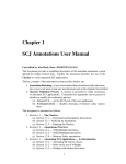
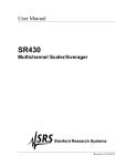
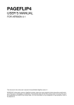
FS-404 CONTROLS AND INDICATORS
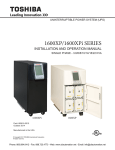
1 2 3 4 5 13 26 14 25 24 23 22 21
31 29 30 28 9 10 11 12 6 8 7 15 16 17 18 27
45
43
46
I
MlllllimilMMM
WARNING
A_
MT"^»
££«
©
CAUTION
A
! i'1.'. ",:' ', SSL
.
• -•^•iut"tunjtiit
nm
• K T "
Mwmmon
SEflWU. NOr 2207 m s
ce®,®A
44
42
41
-15-
FS-404 CONTROLS AND INDICATORS
GND:
Opens signal path and grounds input to vertical
amplifier. This provides a zero-volt base line,
the position of which can be used as a reference
when performing dc measurements.
DC:
Direct coupling of channel 1 input signal; both
AC and DC components of signal produce vertical
deflection.
GENERAL FUNCTION CONTROLS
1. ON Indicator. Lights when oscilloscope is "on".
2. POWER Pushbutton. Turns: oscilloscope"on"
and "off'.
3. INTENSITY Control. Adjusts brightness of trace.
4. TRACE ROTATION Control. Adjusts to maintain
trace at a horizontal position.
5. FOCUS Control. Adjusts trace focus.
6. GND = Terminal. Oscilloscope chassis ground
jack, and earth ground via three-wire ac power
cord.
7. CAL Terminal. Terminal provides 2Vp-p, 1kHz
(nominal) square wave signal. This signal is useful
for checking probe compensation adjustment, as
well as providing a rough check of vertical
calibration.
VERTICAL CONTROLS
8.VERTical MODE Switch. Selects vertical display
mode. Four-position lever switch with the following
positions :
CHI:
Displays the channel 1 signal by itself.
CH2/X-Y:
CH2:displays the channel 2 signal by itself.
X-Y:used in conjunction with the X-Y control
and Trigger SOURCE switch to enable X-Y
display mode.
DUAL
Displays the channel 1 and channel 2.signals
simultaneously. Dual-trace mode may be either
alternate or chopped sweep: see the description
under HOLDOFF/PULL CHOP control.
ADD:
The inputs from channel 1 and channel 2 are
summed and displayed as a single signal. If the
Channel 2 POSition/PULL INVert control is
pulled out, the input from channel 2 is subtracted
from channel 1 and the difference is displayed as a
single signal.
9. CHI AC-GND-DC Switch. Three-position lever
switch with the following positions:
AC:
Channel 1 input signal is capacitively coupled;
DC component is blocked.
10. CHI (X) Input Jack. Vertical input for channel 1.
X-axis input for X-Y operation.
11. CHI (X) VOLTS/DIV Control. Vertical attenuator
for channel 1. Provides step adjustment of vertical
sensitivity. When channel 1 VARiable control
is set to (CAL), vertical sensitivity is calibrated in
10 steps from 5 mV/div to 5 V/div in a 1-2-5
sequence. When the X-Y mode of operation is
selected, this control provides step adjustment
of X-axis sensitivity.
12. CHI VARiable/PULL X5 MAG Control:
VARiable:
Rotation provides vernier adjustment of channel 1
vertical sensitivity. In the fully-clockwise (CAL)
position, the vertical attenuator is calibrated.
Counterclockwise rotation decreases gain sensitivity.
In X-Y operation, this control becomes the vernier
X-axis sensitivity control.
PULL X5 MAG:
When pulled out, increases vertical sensitivity by
a factor of five. Effectively provides two extra
sensitivity settings: 2 mV/div and 1 mV/div. In
X-Y mode, increases X-sensitivity by a factor
of five.
13. CHI POSition/PULL ALT TRIGger Control:
POSition:
Adjusts vertical position of channel 1 trace.
PULL ALT:
Used in conjunction with the Trigger SOURCE
switch to activate alternate triggering. See the
description under the Trigger SOURCE switch.
14. CH2 POSition/PULL INVert Control:
POSition:
Adjusts vertical position of channel 2 trace. In X-Y
operation, rotation adjusts vertical position of X-Y
display.
-16-
FS-404 CONTROLS AND INDICATORS
GND:
Opens signal path and grounds input to
vertical amplifier. This provides a zero-volt
base line, the position of which can be
used as a reference when performing dc
measurements.
DC:
Direct coupling of channel 2 input
signal; bom ac and dc components of
signal produce vertical deflection.
PULL INVert:
When pushed in, the polarity of the
channel 2 signal is normal. When pulled
out, the polarity of the channel 2 signal
is reversed, thus inverting the waveform.
15. CH2 VOLTS/DIV Control. Vertical
attenuator for channel 2. Provides step
adjustment of vertical sensitivity. When
channel 2 VARiable control is set to CAL,
vertical sensitivity is calibrated in 10
steps from 5 mV/div to 5 V/div in a 1-2-5
sequence When the X-Y mode of operation
is selected, this control provides step
adjustment of Y-axis sensitivity.
16. CH2 VARiable/PULLX5 MAG Control:
VARiable:
Rotation provides vernier adjustment
of channel 2 vertical sensitivity. In the
fully-clockwise (CAL) position, the
vertical attenuator is calibrated.
Counterclockwise rotation decreases
gain sensitivity. In X-Y operation, the
vernier this control becomes Y-axis
sensitivity control.
PULL X5 MAG:
When pulled out, increases vertical
sensitivity by a factor of five. Effectively
provides two extra sensitivity settings:
2 mV/div and 1 mV/div. In X-Y mode,
increases Y-sensitivity by a factor of five.
17. CH2 (Y) Input Jack. Vertical input for
channel 2.Y-axis input for X-Y operation.
18. CH2 AC-GND-DC Switch. Three-position
lever switch with the following positions:
AC:
Channel 2 input signal is capacitively
coupled; DC component is blocked.
HORIZONTAL CONTROLS
19. Main Time Base TIME/DIV Control.
Provides step selection of sweep rate for
the main time base. When the VARiable
Sweep control is set to(CAL), sweep rate ,
is calibrated. This control has 23 steps
from 0.1 mS/div to 2 S/div, in a 1-2-5
sequence.
20. VARiable Sweep Control. Rotation of control
is vernier adjustment for sweep rate. In fully
clockwise (CAL) position, sweep rate is
calibrated.
21. POSition/PULL X10 MAG Control.
POSition:
Horizontal (X) position control.
PULL X10 MAG:
Selects ten times sweep magnification when
pulled out, normal when pushed in. Increases
maximum sweep rate to 10 nS/div.
22. X-Y Switch. Used with the VERTical
MODE switch and Trigger SOURCE switch
to select X-Y operating mode. The channel 1
input becomes the X-axis and the channel 2
input becomes the Y-axis. Trigger source and
coupling are disabled in this mode.
-17-
FS-404 CONTROLS AND INDICATORS
TRIGGERING CONTROLS
23. HOLDOFF/PULL CHOP Control.
HOLDOFF:
Rotation adjusts holdoff time (trigger inhibit
period beyond sweep duration). When control
is rotated fully counterclockwise, the holdoff
period is MINinum (normal). The holdoff
period increases progressively with clockwise
rotation.
PULL CHOP:
When this switch is pulled out in the dual-trace
mode, the channel 1 and channel 2 sweeps are
chopped and displayed simultaneously
(normally used at slower sweep speeds). When
it is pushed in, the two sweeps are alternately
displayed, one after the other (normally used
at higher sweep speeds).
24. Trigger SOURCE Switch. Selects source of
sweep trigger. Four-position lever switch with
the following positions:
CH1/X-Y/ALT:
CHI:
Causes the channel 1 input signal to become
the sweep trigger, regardless of the VERTical
MODE switch setting.
X-Y
Used with two other switches to enable the
X-Y mode -see theOperating Instructions
under "XY Operation".
ALT:
Used with the channel 1 POSition/PULL
ALTernate TRIGger control to enable alternate
triggering. Alternate triggering, used in
dualtrace mode, permits each waveform
viewed to become its own trigger source.
CH2:
The channel 2 signal becomes the sweep
trigger, regardless of the VERTical MODE
switch setting.
LINE:
Signal derived from input line voltage
(50/60 Hz)becomes trigger.
EXT:
Signal from EXTernal TRIGger jack
becomes sweep trigger.
25. Trigger COUPLING Switch. Selects trigger
coupling. Four-position lever switch with the
following positions:
AUTO:
Selects automatic triggering mode. In this
mode, the oscilloscope generates sweep
(free runs) in absence of an adequate trigger;
it automatically reverts to triggered sweep
operation when an adequate trigger signal is
present.
NORM:
Selects normal triggered sweep operation.
A sweep is generated only when an adequate
trigger signal is present.
TV-V:
Used for triggering from television vertical sync
pulses. Also serves as lo-pass/DC (high frequency
reject) trigger coupling.
TV-H:
Used for triggering from television horizontal
sync pulses. Also serves as hi-pass (low frequency
reject)trigger coupling.
used at slower sweep speeds). When it is pushed
in, the two sweeps are alternately displayed, one
after the other (normally used at higher sweep
speeds).
26. TRIGger LEVEL/PULL (-) SLOPE Control.
TRIGger LEVEL:
Trigger level adjustment; determines the point
on the triggering waveform where the sweep is
triggered. Rotation in the (-) direction (counter
clockwise)selects more negative triggering point;
rotation in the (+) direction (clockwise) selects
more positive triggering point.
PULL (—)SLOPE:
Two-position push-pull switch. The "in" position
selects a positive-going slope and the "out" position
selects a negative-going slope as triggering point
for main sweep.
27.EXTernal TRIGger jack.External trigger input
for single-and dual-trace operation.
28.FREQ:Turn this knob to set the desired
frequency Generated. This knob is for fine
adjustment.
-18-
FS-404 CONTROLS AND INDICATORS
(NOTE: PULL: EG. DISPLAY For FS-409 only)
29.RANGE: The main Frequency switch of the
Function Generator Each step raise up the
frequency 10 times from 50Hz to 5MHz and
back to 50Hz circulatory. Also the range will
be set at 50Hz automatically when switch on
theOscilloscope, the frequency can be observed
from (34) LED DISPLAY or connect the (45) out
put signal to the (10) INPUT of the oscilloscope
to display on CRT.
30.Function:the Function wave selector to set the
wave from output of the Function Generator
send to the output BNC (45).
31.AMPL/PULL:-20dB/Amplitude knob. Turn the
knob to adjust the amplitude of the output signal
to max 10 time continuously. Or pull out the switch
to attenuate the output signal 20dB(Amplitude
becomes 1/10 level) ?
REAR PANEL CONTROLS
41. Fuse Holder/Line Voltage Selector. Contains
fuse and selects line voltage.
42. Power Cord Receptacle.
43. Handle/lilt Stand.
44. Feet/Cord Wrap.
45.0UTPUT:Function Generator Main output BNC,
output impedance 50fi, Max, amplitude 20Vp-p
for no-load and lOVp-p for50Q load.
46.SYNC: Synchronous output. TTL level Square
wave output with same frequency as the
Main output BNC.
-19-
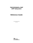
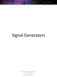
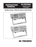
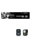
CS-406 CONTROLS AND INDICATORS
1 2 3 4 5 13 26 14 25 24 23 35 34 32
1111111111111111111
A
H^
WARN INC
'WEE:
,.-.
CAUTION
•'WiB^wvai
Ssr-
®
44
42
41
-20-
A
CS-406 CONTROLS AND INDICATORS
GND:
Opens signal path and grounds input to vertical
amplifier. This provides a zero-volt base line,
the position of which can be used as a reference
when performing dc measurements.
DC:
Direct coupling of channel 1 input signal; both
AC and DC components of signal produce vertical
deflection.
GENERAL FUNCTION CONTROLS
1. ON Indicator. Lights when oscilloscope is "on".
2. POWER Pushbutton. Turns: oscilloscope"on"
and "off'.
3. INTENSITY Control. Adjusts brightness of trace.
4. TRACE ROTATION Control. Adjusts to maintain
trace at a horizontal position.
5. FOCUS Control. Adjusts trace focus.
6. GND = Terminal. Oscilloscope chassis ground
jack, and earth ground via three-wire ac power
cord.
7. CAL Terminal. Terminal provides 2Vp-p, 1kHz
(nominal) square wave signal. This signal is useful
for checking probe compensation adjustment, as
well as providing a rough check of vertical
calibration.
VERTICAL CONTROLS
8.VERTical MODE Switch. Selects vertical display
mode. Four-position lever switch with the following
positions :
CHI:
Displays the channel 1 signal by itself.
CH2/X-Y:
CH2:displays the channel 2 signal by itself.
X-Y:used in conjunction with the X-Y control
and Trigger SOURCE switch to enable X-Y
display mode.
DUAL
Displays the channel 1 and channel 2.signals
simultaneously. Dual-trace mode may be either
alternate or chopped sweep: see the description
under HOLDOFF/PULL CHOP control.
ADD:
The inputs from channel 1 and channel 2 are
summed and displayed as a single signal. If the
Channel 2 POSition/PULL INVert control is
pulled out, the input from channel 2 is subtracted
from channel 1 and the difference is displayed as a
single signal.
9. CHI AC-GND-DC Switch. Three-position lever
switch with the following positions:
AC:
Channel 1 input signal is capacitively coupled;
DC component is blocked.
10. CHI (X) Input Jack. Vertical input for channel 1.
X-axis input for X-Y operation.
11. CHI (X) VOLTS/DIV Control. Vertical attenuator
for channel 1. Provides step adjustment of vertical
sensitivity. When channel 1 VARiable control
is set to (CAL), vertical sensitivity is calibrated in
10 steps from 5 mV/div to 5 V/div in a 1-2-5
sequence. When the X-Y mode of operation is
selected, this control provides step adjustment
of X-axis sensitivity.
12. CHI VARiable/PULL X5 MAG Control:
VARiable:
Rotation provides vernier adjustment of channel 1
vertical sensitivity. In the fully-clockwise (CAL)
position, the vertical attenuator is calibrated.
Counterclockwise rotation decreases gain sensitivity.
In X-Y operation, this control becomes the vernier
X-axis sensitivity control.
PULL X5 MAG:
When pulled out, increases vertical sensitivity by
a factor of five. Effectively provides two extra
sensitivity settings: 2 mV/div and 1 mV/div. In
X-Y mode, increases X-sensitivity by a factor
of five.
13. CHI POSition/PULL ALT TRIGger Control:
POSition:
Adjusts vertical position of channel 1 trace.
PULL ALT:
Used in conjunction with the Trigger SOURCE
switch to activate alternate triggering. See the
description under the Trigger SOURCE switch.
14. CH2 POSition/PULL INVert Control:
POSition:
Adjusts vertical position of channel 2 trace. In X-Y
operation, rotation adjusts vertical position of X-Y
display.
-21-
CS-406 CONTROLS AND INDICATORS
GND:
Opens signal path and grounds input to
vertical amplifier. This provides a zero-volt
base line, the position of which can be
used as a reference when performing dc
measurements.
PULL INVert:
When pushed in, the polarity of the
channel 2 signal is normal. When pulled
out, the polarity of the channel 2 signal
is reversed, thus inverting the waveform.
15. CH2 VOLTS/DIV Control. Vertical
attenuator for channel 2. Provides step
adjustment of vertical sensitivity. When
channel 2 VARiable control is set to CAL,
vertical sensitivity is calibrated in 10
steps from 5 mV/div to 5 V/div in a 1-2-5
sequence When the X-Y mode of operation
is selected, this control provides step
adjustment of Y-axis sensitivity.
16. CH2 VARiable/PULLX5 MAG Control:
VARiable:
Rotation provides vernier adjustment
of channel 2 vertical sensitivity. In the
fully-clockwise (CAL) position, the
vertical attenuator is calibrated.
Counterclockwise rotation decreases
gain sensitivity. In X-Y operation, the
vernier this control becomes Y-axis
sensitivity control.
PULL X5 MAG:
When pulled out, increases vertical
sensitivity by a factor of five. Effectively
provides two extra sensitivity settings:
2 mV/div and 1 mV/div. In X-Y mode,
increases Y-sensitivity by a factor of five.
17. CH2 (Y) Input Jack. Vertical input for
channel 2.Y-axis input for X-Y operation.
18. CH2 AC-GND-DC Switch. Three-position
lever switch with the following positions:
AC:
Channel 2 input signal is capacitively
coupled; DC component is blocked.
DC:
Direct coupling of channel 2 input
signal; both AC and DC components of
signal produce vertical deflection.
HORIZONTAL CONTROLS
19. Main Time Base TIME/DIV Control.
Provides step selection of sweep rate for
the main time base. When the VARiable
Sweep control is set to(CAL), sweep rate ,
is calibrated. This control has 23 steps
from 0.1 mS/div to 2 S/div, in a 1-2-5
sequence.
20. VARiable Sweep Control. Rotation of control
is vernier adjustment for sweep rate. In fully
clockwise (CAL) position, sweep rate is
calibrated.
21. POSition/PULL X10 MAG Control.
POSition:
Horizontal (X) position control.
PULL X10 MAG:
Selects ten times sweep magnification when
pulled out, normal when pushed in. Increases
maximum sweep rate to 10 nS/div.
22. X-Y Switch. Used with the VERTical
MODE switch and Trigger SOURCE switch
to select X-Y operating mode. The channel 1
input becomes the X-axis and the channel 2
input becomes the Y-axis. Trigger source and
coupling are disabled in this mode.
-22-
CS-406 CONTROLS AND INDICATORS
TRIGGERING CONTROLS
23. HOLDOFF/PULL CHOP Control.
HOLDOFF:
Rotation adjusts holdoff time (trigger inhibit
period beyond sweep duration). When control
is rotated fully counterclockwise, the holdoff
period is MINinum (normal). The holdoff
period increases progressively with clockwise
rotation.
PULL CHOP:
When this switch is pulled out in the dual-trace
mode, the channel 1 and channel 2 sweeps are
chopped and displayed simultaneously
(normally used at slower sweep speeds). When
it is pushed in, the two sweeps are alternately
displayed, one after the other (normally used
at higher sweep speeds).
24. Trigger SOURCE Switch. Selects source of
sweep trigger. Four-position lever switch with
the following positions:
CH1/X-Y/ALT:
CHI:
Causes the channel 1 input signal to become
the sweep trigger, regardless of the VERTical
MODE switch setting.
X-Y
Used with two other switches to enable the
X-Y mode -see theOperating Instructions
under "XY Operation".
ALT:
Used with the channel 1 POSition/PULL
ALTernate TRIGger control to enable alternate
triggering. Alternate triggering, used in
dualtrace mode, permits each waveform
viewed to become its own trigger source.
CH2:
The channel 2 signal becomes the sweep
trigger, regardless of the VERTical MODE
switch setting.
LINE:
Signal derived from input line voltage
(50/60 Hz)becomes trigger.
EXT:
Signal from EXTernal TRIGger jack
becomes sweep trigger.
25. Trigger COUPLING Switch. Selects trigger
coupling. Four-position lever switch with the
following positions:
AUTO:
Selects automatic triggering mode. In this
mode, the oscilloscope generates sweep
(free runs) in absence of an adequate trigger;
it automatically reverts to triggered sweep
operation when an adequate trigger signal is
present.
NORM:
Selects normal triggered sweep operation.
A sweep is generated only when an adequate
trigger signal is present.
TV-V:
Used for triggering from television vertical sync
pulses. Also serves as lo-pass/DC (high frequency
reject) trigger coupling.
TV-H:
Used for triggering from television horizontal
sync pulses. Also serves as hi-pass (low frequency
reject)trigger coupling.
used at slower sweep speeds). When it is pushed
in, the two sweeps are alternately displayed, one
after the other (normally used at higher sweep
speeds).
26. TRIGger LEVEL/PULL (-) SLOPE Control.
TRIGger LEVEL:
Trigger level adjustment; determines the point
on the triggering waveform where the sweep is
triggered. Rotation in the (-) direction (counter
clockwise)selects more negative triggering point;
rotation in the (+) direction (clockwise) selects
more positive triggering point.
PULL (—)SLOPE:
Two-position push-pull switch. The "in" position
selects a positive-going slope and the "out" position
selects a negative-going slope as triggering point
for main sweep.
27.EXTernal TRIGger jack.External trigger input
for single-and dual-trace operation.
23-
CS-406 CONTROLS AND INDICATORS
32.Hz:the LED lit means the display units are
"Hz".
33.KHz:the LED lit means the display units are
"KHz"
34.LED DIGITS:5 digits to indicade oscilloscope
TRIG'S frequence and EXT. Counter input
frequence and Function Generator wave
frequence.
35.TRIGD/GATE TIME LED:the LED will
be light when the signal was trigger by
the counter circuit Each flash of the LED
means the new data been calculated and been
display. The time between two flash of the
LED is the Gate time. If the counter system
can not detect a new signal for lOsec. The
display will be reset automatically. When
the signal was input from the input BNC of
CHI, CH2 or EXT of the oscilloscope The
trigger condition can be adjusted by (26) TRIG
LEVEL knob. The Gate time are controled
by the CPU from 0.25sec to lOsec automatically.
REAR PANEL CONTROLS
41. Fuse Holder/Line Voltage Selector. Contains
fuse and selects line voltage.
42. Power Cord Receptacle.
43. Handle/Tilt Stand.
44. Feet/Cord Wrap.
-24-
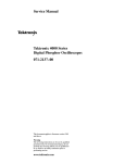
FS-409 CONTROLS AND INDICATORS
1 2 3 4 5 13 26 14 25 24 23 35 34 32
31
29 30 28 9
10 12 11 6 8 7
45
44
42
46
41
-25-
43
16 15 17 18 27 20
FS-409 CONTROLS AND INDICATORS
GND:
Opens signal path and grounds input to vertical
amplifier. This provides a zero-volt base line,
the position of which can be used as a reference
when performing dc measurements.
DC:
Direct coupling of channel 1 input signal; both
AC and DC components of signal produce vertical
deflection.
GENERAL FUNCTION CONTROLS
1. ON Indicator. Lights when oscilloscope is "on".
2. POWER Pushbutton. Turns: oscilloscope"on"
and "off'.
3. INTENSITY Control. Adjusts brightness of trace.
4. TRACE ROTATION Control. Adjusts to maintain
trace at a horizontal position.
5. FOCUS Control. Adjusts trace focus.
6. GND = Terminal. Oscilloscope chassis ground
jack, and earth ground via three-wire ac power
cord.
7. CAL Terminal. Terminal provides 2Vp-p, 1kHz
(nominal) square wave signal. This signal is useful
for checking probe compensation adjustment, as
well as providing a rough check of vertical
calibration.
VERTICAL CONTROLS
8.VERTical MODE Switch. Selects vertical display
mode. Four-position lever switch with the following
positions :
CHI:
Displays the channel 1 signal by itself.
CH2/X-Y:
CH2:displays the channel 2 signal by itself.
X-Y:used in conjunction with the X-Y control
and Trigger SOURCE switch to enable X-Y
display mode.
DUAL
Displays the channel 1 and channel 2.signals
simultaneously. Duai-trace mode may be either
alternate or chopped sweep: see the description
under HOLDOFF/PULL CHOP control.
ADD:
The inputs from channel 1 and channel 2 are
summed and displayed as a single signal. If the
Channel 2 POSition/PULL INVert control is
pulled out, the input from channel 2 is subtracted
from channel 1 and the difference is displayed as a
single signal.
9. CHI AC-GND-DC Switch. Three-position lever
switch with the following positions:
AC:
Channel 1 input signal is capacitively coupled;
DC component is blocked.
10. CHI (X) Input Jack. Vertical input for channel 1.
X-axis input for X-Y operation.
11. CHI (X) VOLTS/DIV Control. Vertical attenuator
for channel 1. Provides step adjustment of vertical
sensitivity. When channel 1 VARiable control
is set to (CAL), vertical sensitivity is calibrated in
10 steps from 5 mV/div to 5 V/div in a 1-2-5
sequence. When the X-Y mode of operation is
selected, this control provides step adjustment
of X-axis sensitivity.
12. CHI VARiable/PULL X5 MAG Control:
VARiable:
Rotation provides vernier adjustment of channel 1
vertical sensitivity. In the fully-clockwise (CAL)
position, the vertical attenuator is calibrated.
Counterclockwise rotation decreases gain sensitivity.
In X-Y operation, this control becomes the vernier
X-axis sensitivity control.
PULL X5 MAG:
When pulled out, increases vertical sensitivity by
a factor of five. Effectively provides two extra
sensitivity settings: 2 mV/div and 1 mV/div. In
X-Y mode, increases X-sensitivity by a factor
of five.
13. CHI POSition/PULL ALT TRIGger Control:
POSition:
Adjusts vertical position of channel 1 trace.
PULL ALT:
Used in conjunction with the Trigger SOURCE
switch to activate alternate triggering. See the
description under the Trigger SOURCE switch.
14. CH2 POSition/PULL INVert Control:
POSition:
Adjusts vertical position of channel 2 trace. In X-Y
operation, rotation adjusts vertical position of X-Y
display.
-26-
FS-409 CONTROLS AND INDICATORS
GND:
Opens signal path and grounds input to
vertical amplifier. This provides a zero-volt
base line, the position of which can be
used as a reference when performing dc
measurements.
DC:
Direct coupling of channel 2 input
signal; both AC and DC components of
signal produce vertical deflection.
PULL INVert:
When pushed in, the polarity of the
channel 2 signal is normal. When pulled
out, the polarity of the channel 2 signal
is reversed, thus inverting the waveform.
15. CH2 VOLTS/DIV Control. Vertical
attenuator for channel 2. Provides step
adjustment of vertical sensitivity. When
channel 2 VARiable control is set to CAL,
vertical sensitivity is calibrated in 10
steps from 5 mV/div to 5 V/div in a 1-2-5
sequence When the X-Y mode of operation
is selected, this control provides step
adjustment of Y-axis sensitivity.
16. CH2 VARiable/PULLX5 MAG Control:
VARiable:
Rotation provides vernier adjustment
of channel 2 vertical sensitivity. In the
fully-clockwise (CAL) position, the
vertical attenuator is calibrated.
Counterclockwise rotation decreases
gain sensitivity. In X-Y operation, the
vernier this control becomes Y-axis
sensitivity control.
PULL X5 MAG:
When pulled out, increases vertical
sensitivity by a factor of five. Effectively
provides two extra sensitivity settings:
2 mV/div and 1 mV/div. In X-Y mode,
increases Y-sensitivity by a factor of five.
17. CH2 (Y) Input Jack. Vertical input for
channel 2.Y-axis input for X-Y operation.
18. CH2 AC-GND-DC Switch. Three-position
lever switch with the following positions:
AC:
Channel 2 input signal is capacitively
coupled; DC component is blocked.
HORIZONTAL CONTROLS
19. Main Time Base TIME/DIV Control.
Provides step selection of sweep rate for
the main time base. When the VARiable
Sweep control is set to(CAL), sweep rate ,
is calibrated. This control has 23 steps
from 0.1 mS/div to 2 S/div, in a 1-2-5
sequence.
20. VARiable Sweep Control. Rotation of control
is vernier adjustment for sweep rate. In fully
clockwise (CAL) position, sweep rate is
calibrated.
21. POSition/PULL X10 MAG Control.
POSition:
Horizontal (X) position control.
PULL X10 MAG:
Selects ten times sweep magnification when
pulled out, normal when pushed in. Increases
maximum sweep rate to 10 nS/div.
22. X-Y Switch. Used with the VERTical
MODE switch and Trigger SOURCE switch
to select X-Y operating mode. The channel 1
input becomes the X-axis and the channel 2
input becomes the Y-axis. Trigger source and
coupling are disabled in this mode.
-27-
FS-409 CONTROLS AND INDICATORS
TRIGGERING CONTROLS
23. HOLDOFF/PULL CHOP Control.
HOLDOFF:
Rotation adjusts holdoff time (trigger inhibit
period beyond sweep duration). When control
is rotated fully counterclockwise, the holdoff
period is MINinum (normal). The holdoff
period increases progressively with clockwise
rotation.
PULL CHOP:
When this switch is pulled out in the dual-trace
mode, the channel 1 and channel 2 sweeps are
chopped and displayed simultaneously
(normally used at slower sweep speeds). When
it is pushed in, the two sweeps are alternately
displayed, one after the other (normally used
at higher sweep speeds).
24. Trigger SOURCE Switch. Selects source of
sweep trigger. Four-position lever switch with
the following positions:
CH1/X-Y/ALT:
CHI:
Causes the channel 1 input signal to become
the sweep trigger, regardless of the VERTical
MODE switch setting.
X-Y
Used with two other switches to enable the
X-Y mode -see theOperating Instructions
under "XY Operation".
ALT:
Used with the channel 1 POSition/PULL
ALTernate TRIGger control to enable alternate
triggering. Alternate triggering, used in
dualtrace mode, permits each waveform
viewed to become its own trigger source.
CH2:
The channel 2 signal becomes the sweep
trigger, regardless of the VERTical MODE
switch setting.
LINE:
Signal derived from input line voltage
(50/60 Hz)becomes trigger.
EXT:
Signal from EXTernal TRIGger jack
becomes sweep trigger.
25. Trigger COUPLING Switch. Selects trigger
coupling. Four-position lever switch with the
following positions:
AUTO:
Selects automatic triggering mode. In this
mode, the oscilloscope generates sweep
(free runs) in absence of an adequate trigger;
it automatically reverts to triggered sweep
operation when an adequate trigger signal is
present.
NORM:
Selects normal triggered sweep operation.
A sweep is generated only when an adequate
trigger signal is present.
TV-V:
Used for triggering from television vertical sync
pulses. Also serves as lo-pass/DC (high frequency
reject) trigger coupling.
TV-H:
Used for triggering from television horizontal
sync pulses. Also serves as hi-pass (low frequency
reject)trigger coupling.
used at slower sweep speeds). When it is pushed
in, the two sweeps are alternately displayed, one
after the other (normally used at higher sweep
speeds).
26. TRIGger LEVEL/PULL (-) SLOPE Control.
TRIGger LEVEL:
Trigger level adjustment; determines the point
on the triggering waveform where the sweep is
triggered. Rotation in the (-) direction (counter
clockwise)selects more negative triggering point;
rotation in the (+) direction (clockwise) selects
more positive triggering point.
PULL (—)SLOPE:
Two-position push-pull switch. The "in" position
selects a positive-going slope and the "out" position
selects a negative-going slope as triggering point
for main sweep.
27.EXTernal TRIGger jack.External trigger input
for single-and dual-trace operation.
28.FREQ:Turn this knob to set the desired
frequency Generated. This knob is for fine
adjustment.
-28-
FS-409 CONTROLS AND INDICATORS
(NOTE: PULL: EG. DISPLAY For FS-409 only)
29.RANGE: The main Frequency switch of the
Function Generator Eech step raise up the
frequency 10 times from 50Hz to 5MHz and
back to 50Hz circulatory. Also the range will
be set at 50Hz automatically when switch on
theOscilloscope, the frequency can be observed
from 34 LED DISPLAY or connect the 45 out
put signal to the 10 INPUT of the oscilloscope
to display on CRT.
30.Function:the Function wave selector to set the
wave from output of the Function Generator
send to the output BNC 45.
31.AMPL/PULL:-20dB/Amplitude knob. Turn the
knob to adjust the amplitude of the output signal
to max 10 time continuously. Or pull out the switch
to attenuate the output signal 20dB(Amplitude
becomes 1/10 level).
REAR PANEL CONTROLS
41. Fuse Holder/Line Voltage Selector. Contains
fuse and selects line voltage.
42. Power Cord Receptacle.
43. Handle/lilt Stand.
44. Feet/Cord Wrap.
45.0UTPUT:Function Generator Main output BNC,
output impedance 50Q, Max, amplitude 20Vp-p
for no-load and lOVp-p for50Q load.
46.SYNC: Synchronous output. TTL level Square
wave output with same frequency as the
Main output BNC.
32.Hz:the LED lit means the display units are
"Hz".
33.KHz:the LED lit means the display units are
"KHz"
34.LED DIGITS:5 digits to indicade oscilloscope
TRIG'S frequence and EXT. Counter input
frequence and Function Generator wave
frequence.
35.TRIGD/GATE TIME LED:the LED will
be light when the signal was trigger by
the counter circuit Each flash of the LED
means the new data been calculated and been
display. The time between two flash of the
LED is the Gate time. If the counter system
can not detect a new signal for lOsec. The
display will be reset automatically. When
the signal was input from the input BNC of
CHI, CH2 or EXT of the oscilloscope The
trigger condition can be adjusted by (26) TRIG
LEVEL knob. The Gate time are controled
by the CPU from 0.25sec to lOsec automatically.?
-29-
OPERATING INSTRUCTIONS
SAFETY PRECAUTIONS
EQUIPMENT PROTECTION
PRECAUTIONS
C
WARNING
The following precautions must be observed
to help prevent electric shock.
l.When the oscilloscope is used to make
measurements in equipment that contains high
voltage, there is always a certain amount of danger
from electrical shock. The person using the
oscilloscope in such conditions should be a
qualified electronics technician or otherwise
trained and qualified to work in such circumstances.
Observe the TEST INSTRUMENT SAFETY
recommendations listed on the inside front cover
of this manual.
2. Do not operate this oscilloscope with the case
removed unless you are a qualified service
technician. High voltage up to 2100 volts is
present when the unit is operating with the case
removed.
3. The ground wire of the 3-wire ac power plug
places the chassis and housing of the oscilloscope
at earth ground. Use only a 3-wire outlet, and do
not attempt to defeat the ground wire connection
or float the oscilloscope; to do so may pose a
great safely hazard.
4. Special precautions are required to measure or
observe line voltage waveforms with any
oscilloscope. Use the following procedure:
a. Do not connect the ground clip of the probe to
either side of the line. The clip is already at earth
ground and touching it to the hot side of the line
cause possible injury, plus possible damage to
the scope or probe.
b. Insert the probe tip into one side of the line
voltage receptacle, then the other. One side of
the receptacle should be "hot" and produce the
The wave from. The other side of the receptacle is
the ac return and nowaveform should result.
CAUTION
The following precautions will help avoid
damage to the oscilloscope.
1. Never allow a small spot of high brilliance to remain
stationary on the screen for more than a few seconds.
The screen may become permanently burned. A
spot will occur when the scope is set up for X-Y
operation and no signal is applied. Either reduce
the intensity so the spot is barely visible, apply
signal, or switch back to normal sweep operation.
It is also advisable to use low intensity with AUTO
triggering and no signal applied for long periods.
A high intensity trace at the same position could
cause a line to become permanently burned onto
the screen.
2. Do not obstruct the ventilating holes in the case,
as this will increase the scope's internal temperature.
3. Excessive voltage applied to the input jacks may
damage the oscilloscope. The maximum ratings
of the inputs are as follows:
&
CH 1 and CH 2:
400 V dc + ac peak.
EXT TRIG:
300 V dc + ac peak.
4. Always connect a cable from the ground terminal
of the oscilloscope to the chassis of the equipment
under test. Without this precaution, the entire current
for the equipment under test may be drawn through
the probe clip leads under certain circumstances.
Such conditions could also pose a safety hazard,
which the ground cable will prevent.
5. The probe ground clips are at oscilloscope and
earth ground and should be connected only to the
earth ground or isolated common of the equipment
under test. To measure with respect to any point
other than the common, use CH 2 CH 1 subtract
operation (ADD mode and INV1), with the
channel 2 probe to the point of measurement and
the channel 1 probe to the point of reference. Use
this method even if the reference point is a DC
voltage with no signal.
-30-
OPERATING INSTRUCTIONS
Trigger SOURCE to CHI.
All POSition controls and INTENSITY control
centered(pointers facing up).
Main Time Base control to 1 mS/div.
OPERATING TIPS
The following recommendations will help obtain
the best performance from the oscilloscope.
1. Always use the probe ground clips for best results,
attached to a circuit ground point near the point
of measurement. Do not rely solely on an external
ground wire in lieu of the probe ground clips as
undesired signals may be introduced.
2.Press the red POWER pushbutton.
3.A trace should appear on the CRT. Adjust the trace
brightness with the INTENTSITY control, and the
trace sharpness with the FOCUS countrol.
2. Avoid the following operating conditions:
b. High temperature and humidity.
SINGLE TRACE DISPLAY
Either channel 1 or channel 2 may be used for
single-trace operation. To observe a waveform on
channel 1:
c. Mechanical vibration.
1. Perform the steps of the"Initial Starting Procedure".
d. Electrical noise and strong magnetic fields,
such as near large motors, power supplies,
transformers, etc.
2. Connect the probe to the CH 1 (X) input jack.
a. Direct sunlight.
3. Occasionally check trace rotation, probe
compensation, and calibration accuracy of the
oscilloscope using the procedures found in the
MAINTENANCE section of this manual.
4. Terminate the output of a signal generator into its
characteristic impedance to minimize ringing,
especially if the signal has fast edges such as
square waves or pulses. For example, the typical
50 W output of a square wave generator should
be terminated into an external 50 W terminating
load and connected to the oscilloscope with 50 W
coaxial cable.
5. Probe compensation adjustment matches the
prob eto the input of the scope. For best results,
compensation should be adjusted initially, then
the same probe always used with the same channel.
Probe compensation should be readjusted when
a probe from a different oscilloscope is used.
INITIAL STARTING PROCEDURE
Until you familiarize yourself with the use of all
controls, the settings given here can be used as a
reference point to obtain a trace on the CRT in
preparation for waveform observation.
1. Set these controls as follows:
On both models:
VERTical MODE to CHI.
CHI AC/GND/DC to GND.
Trigger COUPLING to AUTO.
3. Connect the probe ground clip to the chassis or
common of the equipment under test. Connect
the probe tip to the point of measurement.
4. Move the CHI AC/GND/DC switch out of the
GND position to either DC or AC.
5. If no waveforms appear, increase the sensitivity
by turning the CH 1 VOLTS/DIV control clockwise
to a position that gives 2 to 6 divisions vertical
deflection.
6. Position the waveform vertically as desired using
the CHI POSition control.
7. The display on theCRT may be unsynchronized.
Refer to the"Triggering"paragraphs in this section
for procedures on setting triggering and sweep
time controls to obtain a stable display showing
the desired number of waveforms.
DUAL TRACE DISPLAY
In observing simultaneous waveforms on channel 1
and 2, the waveforms are usually related in frequency,
or one of the waveforms is synchronized to the other,
although the basic frequencies are different. To
observe two such related waveforms simultaneously,
perform the following:
1. Connect probes to both the CH 1 (X) and CH 2 (Y)
input jacks.
2. Connect the ground clips of the probes to the
chassis or common of the equipment under test.
Connect the tips of the probes to the two points
in the circuit where waveforms are to be measured.
-31-
OPERATING INSTRUCTIONS
3. To view both waveforms simultaneously, set the
VERTical MODE switch to DUAL and select
either ALT (alternate) or CHOP with the PULL
CHOP switch.
4. In the ALT sweep mode (PULL CHOP switch
pushed in), one sweep displays the channel 1
sign a land the next sweep displays the channel 2
signal in an alternating sequence. Alternate sweep
is normally used for viewing high-frequency or
high-speed waveforms at sweep times of 1 ms/div
and faster, but may be selected at any sweep time.
5. In the CHOP sweep mode (PULL CHOP switch
pulled out), the sweep is chopped (switched)
between channel 1 and channel 2. Using CHOP,
one channe ldoes not have to"wait"for a complete
swept display of the other channel. Therefore,
portions of both channel's waveforms are displayed
with the phase relationship between the two
waveforms unaltered. Chop sweep is normally
used for low-frequency or lowspeed waveforms
at sweep times of 1 ms/div and slower; or where
the phase relationship between channel 1 and
channel 2 requires measurement .If chop sweep
is used at sweep times of 0.2 ms/div and faster,
the chop rate becomes a significant portion of the
sweep and may become visible in the displayed
waveform. However, you may select chop sweep
at any sweep time for special applications.
6. Adjust the channel 1 and 2 POSition controls to
place the channel 1 trace above the channel 2 trace.
7. Set the CH 1 and CH 2 VOLTS/DIV controls to
a position that gives 2 to 3 divisions of vertical
deflection for each trace. If the display on the
screen is unsynchronized, refer to the'Tiggering"
paragraphs in this section of the manual for
procedures for setting triggering and sweep time
controls to obtain a stable display showing the
desired number of waveforms.
8. When the VERTicalMODE switch is set to ADD,
the algebraic sum of CH 1 + CH 2 is displayed
as a single trace. When the PULL INV switch is
pulled out, the algebraic difference of CH 1-CH 2
is displayed.
9. If two waveforms have no phase or frequency
relationship, there is seldom reason to observe
both waveforms simultaneously. However, these
oscilloscopes do permit the simultaneous viewing
of two such unrelated waveforms, using alternate
triggering. Refer to the paragraphs on'Triggering
- Trigger SOURCE Switch", for details on alternate
triggering.
TRIGGERING
The Oscilloscopes provide versatility in sync
triggering for ability to obtain a stable, jitter-free
display in single-trace, or dual-trace operation. The
proper settings depend upon the type of waveforms
being observed and the type of measurement desired.
An explanationof the various controls which affect
synchronization is given to help you select the proper
setting over a wide range of conditions.
Trigger COUPLING Switch
1. In the AUTO position, automatic sweep operation
is selected. In automatic sweep operation, the sweep
generator free-runs to generate a sweep without a
trigger signal. However, it automatically switches
to triggered sweep operation if an acceptable trigger
source signal is present. The AUTO position is
handy when first setting up the scope to observe
a waveform; it provides sweep for waveform
observation until other controls can be properly
set. Once the controls are set, operation is often
switched back to the normal triggering mode,
since it is more sensitive. Automatic sweep must
be used for dc measurements and signals of such
low amplitude that they will not trigger the sweep.
2. The NORM position provides normal triggered
sweep operation. The sweep remains at rest until
the selected trigger source signal crosses the
threshold level set by the TRIG LEVEL control.
The trigger causes one sweep to be generated,
after which the sweep again remains at rest until
triggered. In the normal triggering mode, there
will be no trace unless an adequate trigger signal
is present. In the ALT VERTICAL MODE of
dua ltrace operation with the SOURCE switch
also set to ALT, there will be no trace unless both
channel 1 and channel 2 signals are adequate for
triggering. Typically, signals that produce even
one division of vertical deflection are adequate
for normal triggered sweep operation.
3. The TV H and TV V positions are primarily for
viewing composite video waveforms. Horizontal
sync pulses are selected as trigger when the trigger
COUPLING switch is set to the TVH position,
and vertical sync pulses are selected as trigger
when the trigger COUPLING switch is set to the
TV V position. The TV H and TV V positions may
also be used as low frequency reject and high
frequency reject coupling, respectively. Additional
procedures for observing video waveforms are
given later in this section of the manual.
-32-
OPERATING INSTRUCTIONS
Trigger SOURCE Switch
The trigger SOURCE switch (CH 1, CH 2, etc.)
Select sthe signal to be used as the sync trigger.
1. If the SOURCE switch is set to CH 1 (or CH 2)
the channel 1 (or channel 2) signal becomes the
trigger source regardless of the VERTICAL
MODE selection. CH 1, or CH2 are often used
as the trigger source for phase or timing
comparison measurements.
2. By setting the SOURCE switch to ALT (same as
CHI) and PULL ALT TRIG pulled, alternating
triggering mode is activated. In this mode, the
trigger source alternates between CH 1 and CH 2
with each sweep. This is convenient for checking
amplitudes, wave shape, or waveform period
measurements, and even permits simultaneous
observation of two waveforms which are not
related in frequency or period. However, this t
setting is no suitable for phase or timing comparison
measurements. For such measurements, both traces
must be triggered by the same sync signal. Alternate
triggering can only be used in dual-trace mode
(VERT MODE set to DUAL), and with alternate
sweep only (PULL CHOP not engaged).
3. In the LINE position, triggering is derived from
the input line voltage (50/60 Hz) and the trigger
SOURCE switch is disabled. This is useful for
measurements that are related to line frequency.
4. In the EXT position, the signal applied to the EXT
TRIG jack becomes the trigger source. This signal
must have a timing relationship to the displayed
waveforms for a synchronized display.
TRIG LEVEL/PULL (—)SLOPE Control?
(Refer to Fig. 1)
A sweep trigger is developed when the trigger source
signal crosses a preset threshold level. Rotation of the
TRIG LEVEL control varies the threshold level. In
the + direction(clockwise), the triggering threshold
shifts to a more positive value, and in the - direction
(counterclockwise), the triggering threshold shifts to
a more negative value. When
Slope "-
the control is centered, the threshold level is set at the
approximate average of the signal used as the triggering
source. Proper adjustment of this control usually
synchronizes the display.
The TRIG LEVEL control adjusts the start of the
sweep to almost any desired point on a waveform. On
sine wave signals, the phase at which sweep begins is
variable. Note that if the TRIG LEVEL control is
rotated toward its extreme + or - setting, no sweep will
be developed in the normal trigger mode because the
triggering threshold exceeds the peak amplitude of the
sync signal.
When the PULL (—)SLOPE control is set to the +("in)
position, the sweep is developed from the trigger source
waveform as it crosses a threshold level in a positivegoing direction. When the PULL (—)SLOPE control
is set to the-("out")position, a sweep trigger is developed
from the trigger source waveform as it crosses the
threshold level in a negative-going direction.
MAIN TIME BASE Control
Set the Main Time Base TIME/DIV control to display
the desired number of cycles of the waveform. If there
are too many cycles displayed for good resolution,
switch to a faster sweep time. If only a line is displayed,
try a slower sweep time. When the sweep time is faster
than the waveform being observed, only part of it will
be displayed, which may appear as a straight line for a
square wave or pulse waveform.
HOLDOFF Control
(Refer to Fig. 2)
A "holdoff' period occurs immediately after the
completion of each sweep, and is a period during which
triggering of the next sweep is inhibited. The normal
holdoff period varies with sweep rate, but is adequate
to assure complete retrace and stabilization before the
next sweep trigger is permitted. The HOLDOFF control
allows this period to be extended by a variable amount
if desired.
Rsnp
I — Slope "4" Range
A. HnldDll not used
B. Ho I'It'll 1 IS til
Fig-1
Fig-2
-33-
OPERATING INSTRUCTIONS
This control is usually set to the MIN position
(fully counterclockwise) because no additional
holdoff period is necessary. The HOLDOFF
control is useful when a complex series of pulses
appear periodically such as in Fig. 4B. Improper
sync may produce a double image as in Fig. 4A.
Such a display could be synchronized with the VAR
SWEEP control, but this is impractical because time
measurementsare then uncalibrated. An alternate
method of synchronizing the display is with the
HOLDOFF control. The sweep speed remains the
same, but the triggering of the next sweep is
"held off'for the duration selected by the HOLDOFF
control. Turn the HOLDOFF control clockwise
from the MIN position until the sweep starts at the
same point of the waveform each time.
MAGNIFIED SWEEP OPERATION
Since merely shortening the sweep time to magnify
aportion of an observed waveform can result in the
desired portion disappearing off the screen, magnified
display should be performed using magnified sweep.
Using the POSition control, move the desired
portion of waveform to the center of the CRT. Pull
out the PULL XI0 knob to magnify the display ten
times. For this type of display the sweep time is the
Main Time Base TIME/DIV control setting divided
by 10. Rotation of the POSition control can then be
used to select the desired portion of the waveforms.
X-Y OPERATION
X-Y operation permits the oscilloscope to perform
many measurements not possible with conventional
sweep operation. The CRT display becomes an
electronic graph of two instantaneous voltages. The
display may be a direct comparison of the two
voltages such as stereoscope display of stereo signal
outputs. However, the X-Y mode can be used to
graph almost any dynamic characteristic if a
transducer is used to change the characteristic
(frequency, temperature,velocity, etc.) into a voltage.
One common application is frequency response
measurements, where theYaxis corresponds to signal
amplitude and the X axis corresponds to frequency.
1.depress the X-Y switch. Set the Trigger Source and
VERTical MODE switches to X-Y.
2. In this mode, channel 1 becomes the X axis input
and channel 2 becomes the Y axis input. The X
and Y positions are now adjusted using the
POSition and the channel 2 POSition controls
respectively.
3. Adjust the amount of vertical (Y axis) deflection
with the CH 2 VOLTS/DIV and VARIABLE
controls.
4. Adjust the amount of horizontal (X axis) deflection
with the CH 1 VOLTS/DIV and VARIABLE
controls.
VIDEO SIGNAL OBSERVATION
Setting the COUPLING switch to the TV-H or
TV-Vposition permits selection of horizontal or
vertical sync pulses for sweep triggering when
viewing composite video waveforms.
When the TV-H mode is selected, horizontal sync
pulses are selected as triggers to permit viewing of
horizontal lines of video. A sweep time of about 10
ms/div is appropriate for displaying lines of video.
The VAR SWEEP control can be set to display the
exact number of waveforms desired. When the TV-V
mode is selected, vertical sync pulses are selected
as triggers to permit viewing of vertical fields and
frames of video. A sweep time of 2 ms/div is
appropriate for viewing fields of video and 5 ms/div
for complete frames(two interlaced fields) of video.
At most points of measurement, a composite video
signal is of the (-) polarity, that is, the sync pulses
are negative and the video is positive. In this case,
use (-) SLOPE. If the waveform is taken at a circuit
point where the video waveform is inverted, the sync
pulses are positive and the video is negative. In this
case, use (+) SLOPE.
-34-
MAINTENANCE
WARNING
The following instructions are for use by
qualified service personnel only. To avoid
electrical shock, do not perform any servicing
other than contained in the operating
instructions unless you are qualified to do so.
High voltage up to 2000 V is present when
covers are removed and the unit is operating.
Remember that high voltage may be retained
indefinitely on high voltage capacitors. Also
remember that ac line voltage is present on
line voltage input circuits any time the
instrument is plugged into an ac outlet, even
if turned off. Unplug the oscilloscope and
discharge high voltage capacitors before
performing service procedures.
FUSE REPLACEMENT
If the fuse blows, the"ON"indicator will not light
and the oscilloscope will not operate. The fuse
should not normally open unless a problem has
developed in the unit. Try to determine and correct
the cause of the blown fuse, then replace only with
the correct value fuse. For 110/125 V line voltage
operation, use an 1.0A, 250 V fuse. For 220/240
Vline voltage operation, use a 0.8A, 250Vfuse.
The fuse is located on the rear panel adjacent to the
power cord receptacle.
Remove the fuseholder assembly as follows:
1. Unplug the power cord from rear of scope.
2. Insert a small screwdriver in fuseholder slot
(located between fuseholder and receptacle).
Pry fuseholder away from receptacle.
3. When reinstalling fuseholder, be sure that the
fuse is installed so that the correct line voltage
is selected (see LINE VOLTAGE SELECTION).
LINE VOLTAGE SELECTION
To select the desired line voltage, simply insert
the fuse and fuse holder so that the appropriate
voltage is pointed to by the arrow. Be sure to use
the proper value fuse (see label on rear panel).
PERIODIC ADJUSTMENTS
Probe compensation and trace rotation adjustments
should be checked periodically and adjusted if required.
These procedures are given below.
Probe Compensation
1. Connect probes to CH 1 and CH 2 input jacks.
Perform procedure for each probe, one probe at
a time.
2. Set the probe to X10 (compensation adjustment
is not possible in the XI position).
3. Touch tip of probe to CAL terminal.
4. Adjust oscilloscope controls to display 3 or 4
cycles of CAL square wave at 5 or 6 divisions
amplitude.
5. Adjust compensation trimmer on probe for optimum
square wave (minimum overshoot, rounding off,
and tilt). Refer to Fig. 3.
Correct
CmnipH IISD rlrj M
•
U++ 1 l l 1
H-H;
IB
B
1 •' •
Over
Lonipen&nllon
Insufffclenl
Compensnrlon
Fig-3
Trace Rotation Adjustment
1. Set oscilloscope controls for a single trace display
in CH 1 mode, and with the channel 1 AC-GND-DC
switch set to GND.
2. Use the channel 1 POSition control to position the
trace over the center horizontal line on the graticule
scale. The trace should be exactly parallel with the
horizontal line.
3. Use the TRACEROTATION adjustment on the
fron tpanel to eliminate any trace tilt.
-35-
MAINTENANCE
CALIBRATION CHECK
A general check of calibration accuracy may be
made by displaying the output of the CAL terminal
on the screen. This terminal provides a square wave 1
of 2V p-p. This signal should produce a displayed
waveform amplitude of four divisions at .5 V/div
sensitivity for both channel 1 and 2(with probes set
for direct). With probes set for XI0, thereshould be
four divisions amplitude at 50 mV/div sensitivity.
The VARIABLE controls must be set to CAL during
this check.
NOTE
The CAL signal should be used only as a
general check of calibration accuracy, not
as a signal source for performing recalibration
adjustments; a voltage standard calibrated
at several steps and of 0.3% or better
accuracy is required for calibration
adjustments.
The CAL signal should not be used as a
time base standard.
-36-
APPENDIX
IMPORTANT CONSIDERATIONS FOR RISE TIME
AND FALL TIME MEASUREMENTS
Error in Observed Measurement
The observed rise time (or fall time) as seen on
the CRT is actually the cascaded rise time of the
pulse being measured and the oscilloscope's own
rise time. The two rise times are combined in square
law addition as follows:
Calculated Measurements
For observed rise times of less than 27 ns, the pulse
rise time should be caluclated to eliminate the error
introduced by the cascaded oscilloscope rise time.
Calculate pulse rise time as follows:
/
/
2
2
2~
1 pluse = J ( 1 observed) >y 1 scope)
2~
1 observed = J ( 1 pulse) ~r( 1 scope)
The effect of the oscilloscope's rise time is almost
negligible when its rise time is at least 3 times as
fast as that of the pulse being measured. Thus,
slower rise times may be measured directly from .
the CRT However, for faster rise time pulses, an
error is introduced that increases progressively as
the pulse rise time approaches that of the oscilloscope.
Accurate measurements can still be obtained by
calculation as described below.
Direct Measurements
The Models 404/406/409 oscilloscopes have a
rated rise time of 8.8 ns. Thus, pulse rise times of
about 27ns or greater can be measured directly.
Most fast rise times are measured at the fastest
sweep speed and using XI0 magnification. For the
Models 404/406/409, this sweep rate is 10 ns/div.
A rise time of less than about four divisions at this
sweep speed should be calculated.
Limits of Measurement
Measurements of pulse rise times that are faster
than the scope's rated rise time are not recommended
because a very small reading error introduces significant
error into the calculation. This limit is reached when
the"observed"rise time is about 1.3 times greater than t
he scope's rated rise time, about 12 ns minimum for
the Models 404/406/409.
Probe Considerations
For fast rise time measurements which approach
the limits of measurement, direct connection via 50 W
coaxial cable and 50 W termination is recommended
where possible. When a probe is used, its rise time
is also cascaded in square law addition. Thus the
probe rating should be considerably faster than the
oscilloscope if it is to be disregarded in the
measurement.
-37-