1
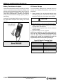
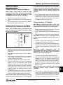
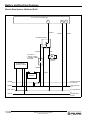
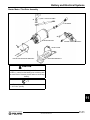
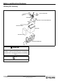
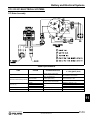
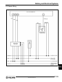
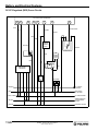
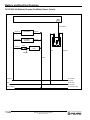
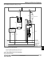
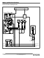
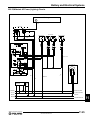
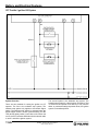
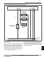
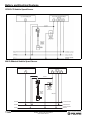
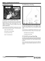
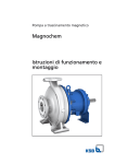
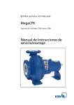
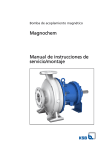
Battery and Electrical Systems CHAPTER 11 Battery and Electrical Systems SPECIFICATIONS . . . . . . . . . . . . . . . . . . . . . . . . . . . . . . . . . . . . . . . . . . . . . . . . . . . . . . 11.2 ENGINE MODELS. . . . . . . . . . . . . . . . . . . . . . . . . . . . . . . . . . . . . . . . . . . . . . . . . . . . . SPARK PLUGS . . . . . . . . . . . . . . . . . . . . . . . . . . . . . . . . . . . . . . . . . . . . . . . . . . . . . . . CHARGING SYSTEM . . . . . . . . . . . . . . . . . . . . . . . . . . . . . . . . . . . . . . . . . . . . . . . . . . IGNITION TIMING . . . . . . . . . . . . . . . . . . . . . . . . . . . . . . . . . . . . . . . . . . . . . . . . . . . . . 11.2 11.2 11.2 11.2 FRESH PACK BATTERY . . . . . . . . . . . . . . . . . . . . . . . . . . . . . . . . . . . . . . . . . . . . . . . . . 11.3 BATTERY PREPARATION . . . . . . . . . . . . . . . . . . . . . . . . . . . . . . . . . . . . . . . . . . . . . . 11.3 SPECIFICATIONS. . . . . . . . . . . . . . . . . . . . . . . . . . . . . . . . . . . . . . . . . . . . . . . . . . . . . 11.3 SEALED BATTERY . . . . . . . . . . . . . . . . . . . . . . . . . . . . . . . . . . . . . . . . . . . . . . . . . . . . . 11.3 SPECIFICATIONS. . . . . . . . . . . . . . . . . . . . . . . . . . . . . . . . . . . . . . . . . . . . . . . . . . . . . 11.3 BATTERY TESTING . . . . . . . . . . . . . . . . . . . . . . . . . . . . . . . . . . . . . . . . . . . . . . . . . . . . 11.3 TESTING PROCEDURES. . . . . . . . . . . . . . . . . . . . . . . . . . . . . . . . . . . . . . . . . . . . . . . OPEN CIRCUIT VOLTAGE TEST (OCV) . . . . . . . . . . . . . . . . . . . . . . . . . . . . . . . . . . . LOAD TEST. . . . . . . . . . . . . . . . . . . . . . . . . . . . . . . . . . . . . . . . . . . . . . . . . . . . . . . . . . BATTERY CONDUCTANCE ANALYZER . . . . . . . . . . . . . . . . . . . . . . . . . . . . . . . . . . . OFF SEASON STORAGE . . . . . . . . . . . . . . . . . . . . . . . . . . . . . . . . . . . . . . . . . . . . . . . 11.3 11.3 11.3 11.4 11.4 IGNITION TIMING . . . . . . . . . . . . . . . . . . . . . . . . . . . . . . . . . . . . . . . . . . . . . . . . . . . . . . 11.5 TIMING PROCEDURE - CARBURETED ENGINES . . . . . . . . . . . . . . . . . . . . . . . . . . . 11.5 TIMING PROCEDURE - CFI ENGINES . . . . . . . . . . . . . . . . . . . . . . . . . . . . . . . . . . . . 11.5 IGNITION TIMING CHART . . . . . . . . . . . . . . . . . . . . . . . . . . . . . . . . . . . . . . . . . . . . . . 11.6 ELECTRIC START - IQ CARBURETED / CFI . . . . . . . . . . . . . . . . . . . . . . . . . . . . . . . . . 11.7 CFI / DC-CFI ELECTRICAL SYSTEMS . . . . . . . . . . . . . . . . . . . . . . . . . . . . . . . . . . . . . 11.13 CFI STATOR ASSEMBLY . . . . . . . . . . . . . . . . . . . . . . . . . . . . . . . . . . . . . . . . . . . . . . DC-CFI STATOR ASSEMBLY. . . . . . . . . . . . . . . . . . . . . . . . . . . . . . . . . . . . . . . . . . . CFI / DC-CFI CHASSIS POWER CAPACITOR . . . . . . . . . . . . . . . . . . . . . . . . . . . . . CFI DC REGULATOR / RECTIFIER . . . . . . . . . . . . . . . . . . . . . . . . . . . . . . . . . . . . . . DC-CFI DC REGULATOR / RECTIFIER . . . . . . . . . . . . . . . . . . . . . . . . . . . . . . . . . . . CFI REGULATOR/RECTIFIER DIODE TESTING. . . . . . . . . . . . . . . . . . . . . . . . . . . . OVER-VOLTAGE/VOLTAGE SPIKE TEST. . . . . . . . . . . . . . . . . . . . . . . . . . . . . . . . . DC-CFI AC REGULATOR/BATTERY CHARGE RECTIFIER . . . . . . . . . . . . . . . . . . . CFI CHASSIS RELAY . . . . . . . . . . . . . . . . . . . . . . . . . . . . . . . . . . . . . . . . . . . . . . . . . DC-CFI REGULATED (RED) POWER CIRCUITS . . . . . . . . . . . . . . . . . . . . . . . . . . . 600 IQ WIDETRAK REGULATED (RED) POWER CIRCUITS . . . . . . . . . . . . . . . . . . DC-CFI/600 IQ WIDETRAK CHASSIS (RED/WHITE) POWER CIRCUITS . . . . . . . . 600 IQ WIDETRAK BRAKE/FAN RELAY CONTROL . . . . . . . . . . . . . . . . . . . . . . . . . DC-CFI AC POWER (LIGHTING) CIRCUITS . . . . . . . . . . . . . . . . . . . . . . . . . . . . . . . 600 IQ WIDETRAK AC POWER (LIGHTING) CIRCUITS . . . . . . . . . . . . . . . . . . . . . . CFI THROTTLE / IGNITION KILL SYSTEM . . . . . . . . . . . . . . . . . . . . . . . . . . . . . . . . DC-CFI/600 IQ WIDETRAK THROTTLE / IGNITION KILL SYSTEM . . . . . . . . . . . . . CFI/DC-CFI VEHICLE SPEED SENSOR . . . . . . . . . . . . . . . . . . . . . . . . . . . . . . . . . . 600 IQ WIDETRAK VEHICLE SPEED SENSOR . . . . . . . . . . . . . . . . . . . . . . . . . . . . 11.13 11.14 11.15 11.15 11.15 11.16 11.17 11.18 11.19 11.20 11.21 11.22 11.23 11.24 11.25 11.26 11.27 11.28 11.28 CARBURETED ELECTRICAL SYSTEMS . . . . . . . . . . . . . . . . . . . . . . . . . . . . . . . . . . . 11.29 DETONATION CONTROL (DET). . . . . . . . . . . . . . . . . . . . . . . . . . . . . . . . . . . . . . . . . . 11.33 OVERVIEW . . . . . . . . . . . . . . . . . . . . . . . . . . . . . . . . . . . . . . . . . . . . . . . . . . . . . . . . . 11.33 VARIABLE EXHAUST SYSTEM (VES) . . . . . . . . . . . . . . . . . . . . . . . . . . . . . . . . . . . . . 11.33 OVERVIEW . . . . . . . . . . . . . . . . . . . . . . . . . . . . . . . . . . . . . . . . . . . . . . . . . . . . . . . . . 11.33 DIAGNOSTIC PLUGS . . . . . . . . . . . . . . . . . . . . . . . . . . . . . . . . . . . . . . . . . . . . . . . . . . 11.34 CARBURETED / CFI CHASSIS POWER PLUG . . . . . . . . . . . . . . . . . . . . . . . . . . . . . 11.34 DC-CFI DC POWER TEST PLUG. . . . . . . . . . . . . . . . . . . . . . . . . . . . . . . . . . . . . . . . 11.34 CFI / DC-CFI FUEL PUMP PRIME PLUG . . . . . . . . . . . . . . . . . . . . . . . . . . . . . . . . . . 11.34 11 ELECTRONIC REVERSE (PERC). . . . . . . . . . . . . . . . . . . . . . . . . . . . . . . . . . . . . . . . . 11.35 9922854 - 2007-2011 IQ Service Manual ©2010 Polaris Sales Inc. 11.1 Battery and Electrical Systems SPECIFICATIONS Ignition Timing Engine Models Model Number Engine EC55PM120/121/122 Fuji 550cc Fan S3273-6044-PF6F S3274-6044-PF6F S3466-6044-PU6F S3467-6044-PU6F Liberty 600cc HO Carbureted S3206-6044-PF6H S3468-6044-PU6H S3469-6044-PU6H S3996-6044-OP6H S4176-6044-OP6H S4177-6044-OP6H S4203-6044-OP6M S4217-6044-OO6H S4216-6044-OO6H S4219-6044-OO6N S4218-6044-OO6H Specification Fuji 550cc Fan 26° @ 4500 RPM 17° @ 6500 RPM ALL 600 CARBURETED 26° @ 3500 RPM (Disconnect TPS) ALL 600/700/800 CFI 18° @ Idle (1700 RPM)/120° Engine Coolant Temperature WARNING PROPOSITION 65 WARNING Liberty 600cc CFI BATTERY POSTS, TERMINALS, AND RELATED ACCESSORIES CONTAIN LEAD AND LEAD COMPOUNDS, CHEMICALS KNOWN TO THE STATE OF CALIFORNIA TO CAUSE CANCER AND REPRODUCTIVE HARM. WASH HANDS AFTER HANDLING. BATTERY ELECTROLYTE IS POISONOUS. IT CONTAINS ACID! SERIOUS BURNS CAN RESULT FROM CONTACT WITH THE S3305-7044-PF7J S3322-7044-PF7J S3470-7044-PU7J S3471-7044-PU7J S4175-7044-OP7J Liberty 700cc CFI S3489-8044-PU8E S3471-8044-PU8E S4001-8044-OP8E S4004-8044-OP8E Liberty 800cc CFI SKIN, EYES, OR CLOTHING . ANTIDOTE: EXTERNAL: FLUSH WITH WATER. INTERNAL: DRINK LARGE QUANTITIES OF WATER OR MILK. FOLLOW WITH MILK OF MAGNESIA, BEATEN EGG, OR VEGETABLE OIL. CALL PHYSICIAN IMMEDIATELY. EYES: FLUSH WITH WATER FOR 15 MINUTES AND GET PROMPT MEDICAL ATTENTION. Spark Plugs Model Model Spark Plug Gap (Inches / mm) BATTERIES PRODUCE EXPLOSIVE GASES. KEEP SPARKS, FLAME, CIGARETTES, ETC. AWAY. VENTILATE WHEN CHARGING OR USING IN CLOSED SPACE. ALWAYS SHIELD EYES Liberty Engines Standard Optional Fuji 550cc Fan WHEN WORKING NEAR BATTERIES. Champion RN57YCC NGK BPR9ES .025 / 0.70 NGK BR9ES .028 / .70 KEEP OUT OF REACH OF CHILDREN. Charging System Model Stator Output # of Pulses Fuji 550cc Fan 280W 6 ALL 600 CARBURETED 280W 6 ALL 600/700/800 CFI N/A 11.2 400W 9922854 - 2007-2011 IQ Service Manual ©2010 Polaris Sales Inc. Battery and Electrical Systems FRESH PACK BATTERY SEALED BATTERY NOTE: Do not service the battery unless it will be put into regular service within 30 days. Specifications Battery PN 4010466 Battery Preparation Some models are equipped with a fresh pack battery. These batteries require filling with electrolyte and a full charge prior to service. 1. Fill battery with electrolyte to the upper level marks on the case. 2. Set battery aside and allow it to cool and stabilize for at least 30 minutes. 3. Add electrolyte to bring the level back to the upper level mark on the case. NOTE: This is the last time that electrolyte should be added. 4. Charge battery at 1/10 of its amp/hour rating. Example:1/10 of 9 amp battery =.9 amps, 1/10 of 14 amp battery = 1.4 amps, 1/10 of 18 amp battery = 1.8 amps (recommended charging rates). 5. Check specific gravity of each cell with a hydrometer to ensure each has a reading of 1.270 or higher. 6. Install vent cover. NOTE: Once the vent cover is installed, the battery is sealed. Do not remove the cover. Specifications Battery PN 4010905 Battery Type Polaris Maintenance Free Nominal Capacity 12 VDC 18 AH @ 10 hour Rate CCA @ 0F (-18C) 270 AMPS Charging Current 1.8A x 5-10 Hours Battery PN 4011224 Battery Type Polaris Maintenance Free Nominal Capacity 12 VDC 14 AH @ 10 hour Rate CCA @ 0F (-18C) 365 AMPS Charging Current 6 AMPS Maximum BATTERY TESTING Testing Procedures Batteries should be kept at or as near full charge as possible. If the battery is stored or used in a partially charged condition, hard crystal sulfication will form on the plates, reducing their efficiency and possibly ruining the battery. Open Circuit Voltage Test (OCV) Battery Type YTX14AH-BS-Fresh Pack Nominal Capacity 12VDC / 12AH Electrolyte Volume 22.3oz. Specific Gravity 1.320 Load Test CCA @ 0F (-18C) 210 AMPS Charging Current 1.2 AMPS A battery may pass the OCV test, but still not have the storage capacity necessary to properly function. Check static battery voltage with multimeter. Voltage should be no less than 12.8 VDC. Charge battery if voltage is lower than 12.8 VDC. 1. Connect multimeter to the battery as if performing the OCV test. 2. Turn the engine over using the electric starter. 3. Replace battery if VDC drops below 9.5VDC. NOTE: Battery load test tools can be purchased commercially. Follow the manufactures’ instructions for use. 9922854 - 2007-2011 IQ Service Manual ©2010 Polaris Sales Inc. 11.3 11 Battery and Electrical Systems Battery Conductance Analyzer Off Season Storage Conductance describes the ability of a battery to conduct current. A conductance tester functions by sending a low frequency AC signal through the battery and a portion of the current response is captured, from this output a conductance measurement is calculated. Conductance testing is more accurate than voltage, specific gravity, or load testing. To prevent battery damage during extended periods of non-use, the following maintenance items must be performed. Authorized Polaris dealers/distributors are required to use the conductance analyzer when testing 12V Polaris batteries. 1. Remove battery from machine and wash the case and battery tray with a mild solution of baking soda and water. Rinse with of fresh water after cleaning. CAUTION DO NOT ALLOW ANY OF THE BAKING SODA SOLUTION TO ENTER THE BATTERY OR THE ACID WILL BE NEUTRALIZED. 2. Using a wire brush or knife, remove any corrosion from the cables and terminals. 3. Charge at a rate no greater than 1/10 of the battery's amp/hr. capacity. 4. Store the battery in a cool, dry place. NOTE: Stored batteries lose their charge at the rate of 1% per day. They should be fully recharged every 30 to 60 days during a non-use period. If stored during winter months, the electrolyte will freeze at higher temperatures as the battery discharges. Specific Gravity Freezing Point Polaris MDX-610P SPX PN: PU-50296 11.4 Specific Gravity of Electrolyte 1.265 1.225 1.200 1.150 1.100 1.050 9922854 - 2007-2011 IQ Service Manual ©2010 Polaris Sales Inc. Freezing Point -75_F (-59_C) -35_F (-37_C) -17_F (-27_C) 5_F (-15_C) 18_F (-8_C) 27_F (-3_C) Battery and Electrical Systems IGNITION TIMING Timing Procedure - Carbureted Engines NOTE: Always verify timing of engine at room temperature (68°F / 20°C), and at the specified RPM. If applicable, make sure the key switch is in the PREMIUM mode and the TPS is unplugged. 1. Reference the timing specification chart. 2. Install a dial indicator gauge into the MAG spark plug hole. 3. Place the MAG piston in the proper timing position, then mark the flywheel at this point. EXAMPLE: 600 HO Carbureted = 26° @ 3500RPM. Place the MAG piston 4.0096mm (0.1579in.) BTDC. NOTE: Each 10 degree mark is separated by lines every 2 degrees (not shown). Acceptable timing variance is +/- 2 degrees. Flywheel Rotation 4. Connect an accurate tachometer and a good quality timing light to the engine according to manufacturer's instructions. 5. Disconnect the throttle position sensor (TPS), if equipped. 6. Start engine and increase RPM to the point specified in the timing specifications. Hold the throttle to maintain specified timing RPM. 7. Point the timing light at the timing inspection hole. 8. With your head positioned so there is a straight line between your eye, the stationary pointer and the crankshaft center line, note the relative position between the marked flywheel line and the pointer. If the stationary pointer is aligned with the mark made in Step 3, or within the acceptable variance, ignition timing is correct. 9. If the pointer is outside the variance, the stator will have to be rotated either with crankshaft rotation (to retard the timing) or against rotation to advance it. NOTE: Rotate stator plate approximately the same distance as the marks must move. In most cases, the recoil starter housing, recoil drive hub, and flywheel must be removed to loosen the stator bolts and change the timing. On some engines, the stator plate retaining screws can be accessed through the flywheel. 10. Torque stator plate screws and flywheel nut to specified torque. Apply Loctite 262 (red) to crankshaft flywheel taper if required. Refer to the Specifications section for torque specifications and flywheel installation procedure for engine type. Timing Procedure - CFI Engines NOTE: Before performing procedure, verify there are no current trouble codes and that all of the engine electrical connections are clean and tight. 1. Reference the timing specification chart and locate the piston BTDC measurement for 18°. 2. Install a dial indicator gauge into the MAG spark plug hole. 3. Place the MAG piston at 18° BTDC. Mark the flywheel. NOTE: Each 10 degree mark is separated by lines every 2 degree. Acceptable timing variance is +/- 2 degrees. 4. Connect a good quality timing light to the engine according to manufacturer's instructions. 5. Start and run the engine at idle speed until the engine temperature is 120°F (49°C). Verify the throttle lever is closed and the engine is at idle speed (1700 +/- 100 RPM). NOTE: The engine temperature must be approximately 120°F (49°C) to obtain accurate timing specification. Use the MFD digital temperature display to view engine temperature. 6. Point the timing light at the timing inspection hole. 7. With your head positioned so there is a straight line between your eye, the stationary pointer and the crankshaft center line, note the relative position between the marked flywheel line and the pointer. If the stationary pointer is aligned with the mark made in Step 3, or within the acceptable variance, ignition timing is correct. NOTE: The stator plate, two-tooth, and five-tooth crankshaft position sensor locations are not adjustable. 8. If the pointer is outside the variance, either the flywheel key has sheared allowing the flywheel to move on the crankshaft, the crankshaft is out of index, a problem with the engine electrical harness exists, or one of the crankshaft position sensors has moved. 9922854 - 2007-2011 IQ Service Manual ©2010 Polaris Sales Inc. 11.5 11 Battery and Electrical Systems Ignition Timing Chart Convert the ignition timing specification from degrees BTDC to either inches or millimeters, then use a dial indicator to verify timing marks. ROD/STROKE (mm) Degrees BTDC 1 2 3 4 5 6 7 8 9 10 11 12 13 14 15 16 17 18 19 20 21 22 23 24 25 26 27 28 29 30 31 32 33 34 35 36 37 38 39 40 11.6 NOTE: Always disconnect the TPS on carbureted engines prior to checking ignition timing. EC55PM120 600 CFI / CARB. 700 CFI 800 CFI 120mm ROD 65mm STROKE 128mm ROD 64mm STROKE 128mm ROD 68mm STROKE 132mm ROD 70mm STROKE MM Inches MM Inches MM Inches MM Inches 0.0063 0.0002 0.0061 0.0002 0.0066 0.0003 0.0067 0.0003 0.0252 0.0010 0.0244 0.0010 0.0262 0.0010 0.0270 0.0011 0.0566 0.0022 0.0548 0.0022 0.0590 0.0023 0.0607 0.0024 0.1006 0.0040 0.0974 0.0038 0.1048 0.0041 0.1078 0.0042 0.1571 0.0062 0.1522 0.0060 0.1637 0.0064 0.1684 0.0066 0.2261 0.0089 0.2190 0.0086 0.2356 0.0093 0.2424 0.0095 0.3076 0.0121 0.2979 0.0117 0.3205 0.0126 0.3298 0.0130 0.4016 0.0158 0.3889 0.0153 0.4184 0.0165 0.4305 0.0169 0.5079 0.0200 0.4919 0.0194 0.5291 0.0208 0.5445 0.0214 0.6265 0.0247 0.6068 0.0239 0.6528 0.0257 0.6717 0.0264 0.7575 0.0298 0.7336 0.0289 0.7892 0.0311 0.8121 0.0320 0.9006 0.0355 0.8723 0.0343 0.9383 0.0369 0.9656 0.0380 1.0559 0.0416 1.0227 0.0403 1.1001 0.0433 1.1321 0.0446 1.2232 0.0482 1.1849 0.0466 1.2745 0.0502 1.3115 0.0516 1.4026 0.0552 1.3586 0.0535 1.4614 0.0575 1.5038 0.0592 1.5938 0.0628 1.5439 0.0608 1.6606 0.0654 1.7089 0.0673 1.7969 0.0707 1.7406 0.0685 1.8722 0.0737 1.9266 0.0758 2.0117 0.0792 1.9487 0.0767 2.0960 0.0825 2.1569 0.0849 2.2380 0.0881 2.1681 0.0854 2.3319 0.0918 2.3996 0.0945 2.4759 0.0975 2.3986 0.0944 2.5798 0.1016 2.6547 0.1045 2.7252 0.1073 2.6402 0.1039 2.8395 0.1118 2.9220 0.1150 2.9857 0.1175 2.8927 0.1139 3.1110 0.1225 3.2013 0.1260 3.2574 0.1282 3.1560 0.1243 3.3941 0.1336 3.4927 0.1375 3.5401 0.1394 3.4300 0.1350 3.6887 0.1452 3.7958 0.1494 3.8336 0.1509 3.7146 0.1462 3.9946 0.1573 4.1106 0.1618 4.1379 0.1629 4.0096 0.1579 4.3117 0.1698 4.4369 0.1747 4.4528 0.1753 4.3149 0.1699 4.6399 0.1827 4.7746 0.1880 4.7782 0.1881 4.6303 0.1823 4.9789 0.1960 5.1235 0.2017 5.1138 0.2013 4.9558 0.1951 5.3287 0.2098 5.4835 0.2159 5.4595 0.2149 5.2911 0.2083 5.6891 0.2240 5.8543 0.2305 5.8152 0.2289 5.6361 0.2219 6.0598 0.2386 6.2358 0.2455 6.1807 0.2433 5.9907 0.2359 6.4408 0.2536 6.6278 0.2609 6.5559 0.2581 6.3546 0.2502 6.8318 0.2690 7.0302 0.2768 6.9405 0.2732 6.7278 0.2649 7.2326 0.2847 7.4427 0.2930 7.3343 0.2888 7.1099 0.2799 7.6431 0.3009 7.8652 0.3097 7.7372 0.3046 7.5010 0.2953 8.0632 0.3174 8.2974 0.3267 8.1491 0.3208 7.9007 0.3111 8.4925 0.3343 8.7392 0.3441 8.5696 0.3374 8.3089 0.3271 8.9308 0.3516 9.1903 0.3618 8.9986 0.3543 8.7254 0.3435 9.7381 0.3692 9.6506 0.3799 9.4360 0.3715 9.1501 0.3602 9.8340 0.3872 10.1198 0.3984 9922854 - 2007-2011 IQ Service Manual ©2010 Polaris Sales Inc. Battery and Electrical Systems ELECTRIC START IQ CARBURETED / CFI System Schematic - 600 Carbureted 11 9922854 - 2007-2011 IQ Service Manual ©2010 Polaris Sales Inc. 11.7 Battery and Electrical Systems Electric Start System - CFI 11.8 9922854 - 2007-2011 IQ Service Manual ©2010 Polaris Sales Inc. Battery and Electrical Systems Electric Start System - DC-CFI DC--CFI ECU CNA CONNECTOR 13 1 3 GRN/WHT KEY SWITCH (CIRCUIT CLOSED WHEN KEY TURNED TO START) BROWN RED/DG WHT/RED STARTER SOLENOID RED/DG RED RED M STARTER MOTOR AC SHUNT REGULATOR DIRECT - + BATTERY BATTERY VOLTAGE RED 10A BREAKER RED/DG BATTERY CHARGE DC VOLTAGE BRN -- DIRECT CH / ENG GROUND YELLOW AC VOLTAGE FROM STATOR 11 9922854 - 2007-2011 IQ Service Manual ©2010 Polaris Sales Inc. 11.9 Battery and Electrical Systems Electric Start System - Widetrak IQ 600 DC--CFI ECU CNA CONNECTOR 13 1 3 GRN/WHT BROWN RED/DG STARTER SOLENOID WHT/RED RED KEY SWITCH (CIRCUIT CLOSED WHEN KEY TURNED TO START) M STARTER MOTOR AC REGULATOR BATTERY CHARGE RED/BLK - + RED/BLK BATTERY BATTERY CHARGE DC VOLTAGE RED/BLK 10A BREAKER RED/BLK 10A PROTECTED DCV BRN -- DIRECT CH / ENG GROUND YELLOW AC VOLTAGE FROM STATOR 11.10 9922854 - 2007-2011 IQ Service Manual ©2010 Polaris Sales Inc. Battery and Electrical Systems Starter Motor / Flex Drive Assembly A (+) RED - POSITIVE CABLE FLEX DRIVE A STARTER MOTOR B PINION / PINION BRACKET A GEAR CLAMP A END PLATE MOUNTING BRACKET MOUNTING BRACKET CAUTION Always disconnect the BLACK (-) cable first, and then the RED (+) cable from the battery prior to working with the starter motor. Reverse process when reconnecting battery. =T A = 8 Ft.Lbs. (11 Nm) B = 15 Ft.Lbs. (20 Nm) 11 9922854 - 2007-2011 IQ Service Manual ©2010 Polaris Sales Inc. 11.11 Battery and Electrical Systems IQ Battery Box Assembly CIRCUIT BREAKER A SOLENOID BATTERY HOLD-DOWN BRACKET GROUND CABLE BATTERY BATTERY PAD A MOUNTING BRACKET CAUTION Always disconnect the BLACK (-) cable first, and then the RED (+) cable from the battery prior to working with the starter motor. Reverse process when reconnecting battery. =T A = 8 Ft.Lbs. (11 Nm) 11.12 9922854 - 2007-2011 IQ Service Manual ©2010 Polaris Sales Inc. Battery and Electrical Systems CFI / DC-CFI ELECTRICAL SYSTEMS CFI Stator Assembly Stator Specifications ITEM Charge Coil (Z) COLOR Chassis / Battery Charge Power Head / Tail Lights Hand / Thumb Warmers Crank Position Sensor (5 Tooth) Ignition timing Crank Position Sensor (2 Tooth) Locates TDC and RPM YELLOWS GRN to WHT/GRN Crank Position Sensors (CPS) (V and W) WHT to WHT/RED Exciter Coils (Y) Injector Coils (X) Ground SYSTEM FUNCTION GRN/RED GRN/YEL BRN/WHT BLU/YEL TO BLU/YEL BROWN RESISTANCE +/- 15% @68°F (20°C) YEL TO YEL = 0.13 NO CONTINUITY TO GROUND GRN to WHT/GRN = 190 WHT to WHT/RED = 190 GRN/RED to GRN/YEL = 15 Exciter Coil - Powers the Ignition Coils / GRN/RED to BRN/WHT = 30 ECU BRN/WHT to Ground = 0 16VDC - Supplies power to fuel injectors. BLU/YEL to BLU/YEL = 2.4 ENGINE GROUND 0 11 9922854 - 2007-2011 IQ Service Manual ©2010 Polaris Sales Inc. 11.13 Battery and Electrical Systems DC-CFI Stator Assembly DC-CFI Stator Specifications ITEM AC Lighting Coil (Y) DC Chassis Coil (Z) DC System Coil (X) CRANK POSITION SENSOR (CPS) ENGINE GROUND 11.14 COLOR RESISTANCE +/- 15% @68°F (20°C) SYSTEM FUNCTION 14VAC Chassis Power - Battery Charge (Electric Start Equipped) - Head / Tail Lights - Hand / Thumb Warmers 14VDC Chassis Power - Fuel Pump YELLOW to YELLOW - Chassis Relay Coil - EV Solenoid - MFD Gauge 16 VDC System Power - Fuel Injector Power ORANGE to ORANGE - ECU / Sensor Power (Regulated to 5VDC) - Ignition Coil Power GRN to WHT/GRN Crank Position Sensor (5 Tooth) Ignition timing Crank Position Sensor (2 Tooth) WHT to WHT/RED Locates TDC and RPM BROWN Engine Ground YELLOW to YELLOW 9922854 - 2007-2011 IQ Service Manual ©2010 Polaris Sales Inc. YELLOW TO YELLOW = 0.12 NO CONTINUITY TO GROUND YELLOW TO YELLOW = 0.20 NO CONTINUITY TO GROUND ORANGE TO ORANGE = 0.72 NO CONTINUITY TO GROUND GRN to WHT/GRN = 190 WHT to WHT/RED = 190 0 Battery and Electrical Systems CFI / DC-CFI Chassis Power Capacitor DC-CFI DC Regulator / Rectifier Capacitor Testing 1. Charge the capacitor for 10 seconds using a 12 volt battery by connecting the positive (+) lead to the Red/ White wire and the negative (-) lead to the brown wire. 2. Monitor the capacitor voltage with a multimeter. The voltage should slowly drain down from the initial charge. If the cap does not hold a charge or drains rapidly, replace the component. CFI DC Regulator / Rectifier DC-CFI DC Regulator / Rectifier Connections CONNECTOR WIRE COLORS Stator YELLOW VAC from stator coils. ECU VDC supplied to ECU to ORANGE boost power to fuel pump during engine start-up. Chassis BROWN RED ITEM 14.5 VDC Chassis power. CFI DC Regulator / Rectifier Connections CONNECTOR WIRE COLORS Stator YELLOW ECU VDC supplied to ECU to ORANGE boost power to fuel pump during engine start-up. Chassis BROWN RED ITEM VAC from stator charge coils. 14.5 VDC chassis power. 11 9922854 - 2007-2011 IQ Service Manual ©2010 Polaris Sales Inc. 11.15 Battery and Electrical Systems CFI Regulator/Rectifier Diode Testing The CFI regulator/rectifiers, PNs: 4011731 and 4012476, can be tested using a multimeter. Set multimeter to DIODE CHECK MODE. OL equals OPEN LINE. 0 equals zero OHMS. Disconnect all wire connectors before testing. Always test the regulator/rectifier after replacing a damaged ECU. A faulty regulator/rectifier can damage the ECU. TERMINAL VIEWS A B A B DC SUPPLY C D E AC SUPPLY 4011731 / 4012476 CFI Regulator/Rectifier Testing MULTIMETER NEGATIVE LEAD (BLACK) MULTIMETER POSTIVE LEAD (RED) A (RED) B (BROWN) C (YELLOW) D (YELLOW) E (YELLOW) A (RED) OL OL OL B (BROWN) .131 - .731 .132 - .732 .133 - .733 OL OL C (YELLOW) .130 - .730 OL D (YELLOW) .133 - .733 OL OL E (YELLOW) .134 - .734 OL OL OL OL Reading using DIODE CHECK MODE. Measure at 68° F (20° C). Disconnect all wire connectors before testing. Shaded boxes indicate no test. 11.16 9922854 - 2007-2011 IQ Service Manual ©2010 Polaris Sales Inc. Battery and Electrical Systems Over-Voltage / Voltage Spike Test The diode check test cannot be used to determine if the regulator / rectifier has supplied the ECU with voltage spikes. To determine if the regulator / rectifier has damaged the ECU with voltage spikes, the potting material on the backside of the ECU must be inspected. If the ECU has been damaged by over-voltage, the potting material in the shaded region will be melted, discolored, or bubbled. If potting material is damaged in the shaded region, replace the ECU and voltage regulator / rectifier. 11 9922854 - 2007-2011 IQ Service Manual ©2010 Polaris Sales Inc. 11.17 Battery and Electrical Systems DC-CFI AC Regulator/Battery Charge Rectifier DC-CFI models feature an AC regulator/DC (battery charge) rectifier. 600 IQ Widetrak versions also supply DC power to drive the radiator fan motor. 2009 DC-CFI AC Regulator Circuit Specifications PLUG/PIN/COLOR FUNCTION 1 - RED 14.7V BATTERY (+) 2 - YELLOW 14.3 ACV (FROM STATOR) 3 - BROWN GROUND (-) 2010 600 IQ Widetrak AC Regulator Circuit Specifications PLUG/PIN/COLOR FUNCTION A - RED/BLK 14.7V BATTERY (+) B - YELLOW 14.3 ACV (FROM STATOR) C - BROWN GROUND (-) D - BLK/WHT FAN GROUND (-) E - ORG/BLK FAN POWER (+) 11.18 9922854 - 2007-2011 IQ Service Manual ©2010 Polaris Sales Inc. Battery and Electrical Systems CFI Chassis Relay 11 9922854 - 2007-2011 IQ Service Manual ©2010 Polaris Sales Inc. 11.19 Battery and Electrical Systems DC-CFI Regulated (RED) Power Circuits DC--CFI ECU CNA CONNECTOR 20 21 30 34 17 19 7 33 ORG WHT/DK.BLUE ORG BLK/BLU BRN/YEL RED RED ORG DIGITAL WRENCH PLUG WHT/YEL RED/WHT CHASSIS RELAY FUEL PUMP PRIME PLUG ORG EV SOLENOID RED BLK/ BLU M REGULATOR RECTIFIER RED FUEL PUMP EXT. POWER PLUG CAPACITOR RED/WHT DC CHASSIS VOLTAGE RED REGULATED DC VOLTAGE BRN -- DIRECT CH / ENG GROUND YELLOW UNREGULATED AC VOLTAGE FROM STATOR ORANGE EXTERNAL POWER 11.20 9922854 - 2007-2011 IQ Service Manual ©2010 Polaris Sales Inc. Battery and Electrical Systems 600 IQ Widetrak Regulated (RED) Power Circuits DC--CFI ECU CNA CONNECTOR 20 21 30 34 19 17 33 ORG WHT/DK.BLUE ORG BRN/YEL RED RED ORG DIGITAL WRENCH PLUG WHT/YEL RED/WHT CHASSIS RELAY FUEL PUMP PRIME PLUG ORG EV SOLENOID RED M REGULATOR RECTIFIER RED FUEL PUMP EXT. POWER PLUG CAPACITOR ORG RED/WHT DC CHASSIS VOLTAGE RED REGULATED DC VOLTAGE BRN -- DIRECT CH / ENG GROUND YELLOW UNREGULATED AC VOLTAGE FROM STATOR ORANGE EXTERNAL POWER 11 9922854 - 2007-2011 IQ Service Manual ©2010 Polaris Sales Inc. 11.21 Battery and Electrical Systems DC-CFI/600 IQ Widetrak Chassis (Red/White) Power Circuits DC--CFI ECU CNA CONNECTOR 33 WHT/DK.BLUE RED/WHT MFD POWER BROWN RED/WHT DC POWER TEST PLUG BROWN RED/WHT 2 AMP CHASSIS RELAY ACCESSORY PLUG RED RED/WHT RED/YEL BROWN RED/WHT DC CHASSIS VOLTAGE RED REGULATED DC VOLTAGE BRN -- DIRECT CH / ENG GROUND 11.22 9922854 - 2007-2011 IQ Service Manual ©2010 Polaris Sales Inc. Battery and Electrical Systems 600 IQ Widetrak Brake/Fan Relay Control MFD GAUGE DC--CFI ECU CNA CONNECTOR 24 22 ORG YEL/BLK ORG BRAKE SWITCH ORG/BLK RED BRN FAN RELAY RED ORG/BLK BRAKE RELAY ORG/BLK BLK/WHT M ORG FAN MOTOR AC REGULATOR BATTERY CHARGE RECTIFIER RED BRN/WHT BRN RED YELLOW BRN TAIL LAMP RED REGULATED DC VOLTAGE BRN -- DIRECT CH / ENG GROUND YELLOW UNREGULATED AC VOLTAGE FROM STATOR BRN/WHT THUMB/HAND WARMER GROUNDS 600 IQ Widetrak Fan Control Parameters 11 • Fan ON = Engine temperature above 149° F/65° C. • Fan Off = Engine temperature below 134° F/57° C. NOTE: Engine RPM must be at least 1,500 RPM for ECU to drive the fan motor. 9922854 - 2007-2011 IQ Service Manual ©2010 Polaris Sales Inc. 11.23 Battery and Electrical Systems DC-CFI AC Power (Lighting) Circuits MFD Gauge 26 22 YEL OR/BLK HEAD LIGHTS BRN BRAKE SIGNAL CONVERTER ORG GRN YEL BRN THUMB WARMER HAND WARMERS YEL TAIL / BRAKE LAMP OR/GRN GY/WH BLUE BLU/RED BRN LH CONTROLS ORG YEL BRN YEL BRN AC REGULATOR RECTIFIER BRN AC POWER TEST BRAKE SWITCH YEL RED/GRN BATTERY VOLTAGE YELLOW AC STATOR VOLTAGE BROWN GROUND 11.24 9922854 - 2007-2011 IQ Service Manual ©2010 Polaris Sales Inc. Battery and Electrical Systems 600 IQ Widetrak AC Power (Lighting) Circuits MFD Gauge 26 YELLOW HEAD LIGHTS THUMB WARMER HAND WARMERS PASSENGER WARMERS GREEN YEL/BLK BRN BLU/RED BLUE GRY/WHT HI/LOW SWITCH ORG/GRN TAIL / BRAKE LAMP BRN/WHT YEL YEL BRN/WHT BRN AC REGULATOR RECTIFIER AC POWER TEST RED/GRN BATTERY VOLTAGE YELLOW AC STATOR VOLTAGE BROWN GROUND BRN/WHT SWITCHED GROUND 9922854 - 2007-2011 IQ Service Manual ©2010 Polaris Sales Inc. 11.25 11 Battery and Electrical Systems CFI Throttle / Ignition Kill System System Overview There are two methods for cutting the ignition on CFI systems. The first is the software stop system. The software stop system only applies to the throttle flipper switch. The software stop system is activated when the throttle flipper switch is closed (closed throttle), but the TPS (throttle plate position) is still above idle. When this occurs, the ECU software will determine the throttle cable is “stuck” and kill the ignition system. 11.26 The second system is the hardware stop system. The hardware stop system is a direct ignition kill system. That is, whenever the operator turns the key to off, pulls the tether, or pushes the safety slap switch down, the ignition system is immediately killed. 9922854 - 2007-2011 IQ Service Manual ©2010 Polaris Sales Inc. Battery and Electrical Systems DC-CFI/600 IQ Widetrak Throttle / Ignition Kill System DC--CFI ECU CNA CONNECTOR 25 9 7 15 16 BLK IGNITION SWITCH (CLOSED WHEN KEY TURNED TO OFF) BLK/RED TETHER SWITCH (OPTIONAL) THROTTLE FLIPPER SWITCH (CLOSED THROTTLE = CLOSED CIRCUIT) SAFETY SLAP SWITCH (PUSHED DOWN = CLOSED CIRCUIT) BLK/BLU SENSOR GROUND CHASSIS / ENGINE GROUND BRN System Overview There are two methods for cutting the ignition on DC-CFI systems. The first is the software stop system. The software stop system only applies to the throttle flipper switch. The software stop system is activated when the throttle flipper switch is closed (closed throttle), but the TPS (throttle plate position) is still above idle. When this occurs, the ECU software will determine the throttle cable is “stuck” and kill the ignition system. The second system is the hardware stop system. The hardware stop system is a direct ignition kill system. That is, whenever the operator turns the key to off, pulls the tether, or pushes the safety slap switch down, the ignition system is immediately killed. 9922854 - 2007-2011 IQ Service Manual ©2010 Polaris Sales Inc. 11 11.27 Battery and Electrical Systems CFI/DC-CFI Vehicle Speed Sensor 600 IQ Widetrak Vehicle Speed Sensor ECU CNA CONNECTOR MULTIFUNCTION INSTRUMENT (GAUGE) 19 8 12 5 6 OG/WHT GROUND SPEED CAPACITOR GROUND SPEED SENSOR 11.28 BRN/WHT RED/WHT CHASSIS VOLTAGE GRN/RED SIGNAL RETURN BROWN CHASSIS / ENGINE GROUND 9922854 - 2007-2011 IQ Service Manual ©2010 Polaris Sales Inc. Battery and Electrical Systems CARBURETED ELECTRICAL SYSTEMS 550 Stator Specifications Specifications 600 HO Stator Specifications NOTE: Use a multimeter to test the stator circuits. Remember to test the circuits when the engine is cold and after the engine has been running for some time. Specifications YEL TO BRN 0.15 BRN TO ENGINE 0 BLK / RED TO GRN 15 RED TO GRN 15 YEL TO BRN 0.16 BRN TO ENGINE 0 BLK / RED TO GRN 13 RED TO GRN 13 RED TO ENGINE OPEN BLK TO ENGINE 0 WHT / RED TO WHT 185 WHT TO ENGINE OPEN Ignition Coil Packs BLK or WHT TO ENGINE 0 WHT / RED TO WHT Specifications 185 BLK TO WHT (Primary) 0.3 BLK or WHT TO SECONDARY LEAD OPEN SECONDARY LEAD TO LEAD 5K PLUG CAPS 10K Exhaust Valve Solenoid Specifications Coil Resistance (WHT/YEL to RED) 9922854 - 2007-2011 IQ Service Manual ©2010 Polaris Sales Inc. 15 +/- 15% @ 68°F (20°C) 11 11.29 Battery and Electrical Systems Knock Sensor Throttle Position Sensor (TPS) The TPS is located on the carburetor rack. The TPS is set at the time of manufacture and should only require adjustment when: • When the TPS is replaced. 600HO Coolant Temperature Sensor • When the carburetor rack or throttle body is replaced or adjusted. • The TPS is suspected of being set incorrectly as part of troubleshooting. The TPS test tool, PN 2201519, is used to accurately adjust the TPS return signal settings. TPS Test Tool Setup NOTE: Signal readings can be affected if the 9 volt battery is weak. Always verify the battery is in good condition. Sensor Specifications Operating Temperature Range -22_F - +248 _F (-30_C 120_C) Resistance 2.4 - 2.6K@ 68_F (20_C) (Measure in stirred water) Installation Torque 29 ft.lbs. (39.2Nm) 1. Set the multimeter to read VDC. 2. Verify the 9 volt battery condition by inserting the black multimeter probe into the black wire terminal and the red multimeter probe into the pink wire terminal. Voltage should read 4.99 to 5.01 VDC. Use a new battery if voltage is below 4.99 VDC. Black Probe Oil Level Sender Red Probe To test the oil level sender, position the sender as it would be in the oil tank. Allow the float to drop in the direction it would if the oil tank were empty. Continuity should be present when using a multimeter to test the sender with the float in the “empty” position. No continuity should be present when the float is moved away from the “empty” position. 11.30 Black Red Pink 3. Connect the test tool to the TPS on the carburetor or throttle body. 9922854 - 2007-2011 IQ Service Manual ©2010 Polaris Sales Inc. Battery and Electrical Systems TPS Adjustment NOTE: Always verify the engine idle speed is set at engine operating temperature and the throttle cable freeplay is set to 0.10 - 0.30. 1. Connect the TPS test tool to the TPS. 2. Slightly loosen the screws securing the TPS to carburetor body. 3. Have an assistant hold the throttle flipper in the WOT position. 4. Turn the TPS clockwise to decrease voltage, or counterclockwise to increase voltage. 5. Carefully tighten the TPS screws when the WOT VDC is 4.00VDC. NOTE: Always disconnect the 9 volt battery when tool is not in use. Using the TPS Test Tool 1. Remove the wiring harness connector from the TPS. 2. Verify the throttle cable is not kinked and the throttle flipper is closed. Disconnect the throttle cable from the throttle flipper. 3. Connect the test tool to the TPS. 4. Insert the black multimeter probe into the black terminal port, then insert the red multimeter probe into the yellow terminal port. 5. Reference the specifications to determine if the TPS requires adjustment or replacement. 6. Reconnect the throttle cable with throttle flipper. TPS Setting Specifications ENGINES VOLTAGE SETTINGS Carbureted Engines 4.00 +/- 0.1 VDC @ WOT 7. To verify the TPS is sending a linear signal, slowly move the throttle flipper from the closed to WOT position, then back down to the closed position. 8. The voltage readings should rise and fall without erratically jumping from high to low. NOTE: The multimeter display may change scales and show O.L. momentarily when throttle flipper is moving. 2007 600 HO Regulator / Rectifier This regulator / rectifier performs the following functions: • Regulates AC Voltage to 14.3 volts. • Provides regulated DC voltage to power the MFD gauge. • Provides regulated DC voltage to charge the battery, if equipped. • Illuminates the MFD brake LED indicator by grounding the MFD circuit whenever the module receives an VAC brake light signal (operator pulls brake lever). 11 9. If the signal readings are erratic, replace the TPS sensor. 9922854 - 2007-2011 IQ Service Manual ©2010 Polaris Sales Inc. 11.31 Battery and Electrical Systems Replace the regulator / rectifier whenever the following occurs: • AC voltage is over 14.8 volts when the engine is running. • No DC voltage found on the RED/WHT or RED circuits when the engine is running. • The brake lights illuminate when the brake lever is pulled, but the LED indicator does not. 2008 RMK Shift 155 Regulator / Rectifier The RMK Shift regulator / rectifier performs the same functions as the 2007 600 HO regulator / rectifier. Circuit Specifications Circuit Specifications PLUG / PIN / COLOR FUNCTION STATOR / 2 / BROWN GROUND STATOR / 3 / YELLOW AC POWER INPUT STATOR / 4 / BROWN GROUND STATOR / 6 / YELLOW AC POWER INPUT HARNESS / A / YELLOW REGULATED AC POWER HARNESS / B / ORG/BLK DC BRAKE LAMP GROUND HARNESS / C / ORANGE AC BRAKE SIGNAL INPUT HARNESS / D / BRN/WHT DC GROUND PLUG / PIN / COLOR FUNCTION HARNESS / F / BROWN AC GROUND HARNESS / G / YELLOW REGULATED AC POWER HARNESS / J / RED/WHT REGULATED DC MFD POWER HARNESS / K / RED REGULATED DC BATTERY POWER HARNESS / M / BROWN AC GROUND METAL TAB GROUND PLATE 1 / YEL/BLK AC POWER INPUT 2 / YEL/BLK AC POWER INPUT 4 / RED VDC (BATTERY CHARGE) 5 / RED/WHT VDC (REGULATED FOR MFD) 6 / ORANGE AC BRAKE SIGNAL 7 / YELLOW REGULATED VAC 8 / YELLOW REGULATED VAC 9 / BROWN GROUND 10 / BROWN GROUND 13 / BRN/WHT DC GROUND 14 / ORG/BLK DC BRAKE LAMP GROUND (MFD) 15 / BROWN AC GROUND 16BROWN AC GROUND 2008-2009 IQ Shift 121 Regulator / Rectifier The regulator rectifier on a 2008-2009 IQ Shift 121 limits AC Voltage to 14.3 volts. The module also supplies 12 VDC to power the exhaust valve solenoid. Replace the regulator / rectifier if the AC Voltage is above 14.8 V or when there is no 12 VDC supply on the RED / GREEN circuit. Circuit Specifications PLUG / PIN / COLOR FUNCTION 11.32 YELLOW REGULATED 14.3 VAC POWER RED/GREEN EXHAUST VALVE SOLENOID POWER (VDC) BROWN GROUND 9922854 - 2007-2011 IQ Service Manual ©2010 Polaris Sales Inc. Battery and Electrical Systems DETONATION CONTROL (DET) VARIABLE EXHAUST SYSTEM (VES) Overview Overview Detonation control is achieved by using a knock sensor mounted to the cylinder head and an ECU (CFI engines) or the CDI (600HO carbureted engines). The Polaris VES system uses exhaust valves (1 per cylinder) to control the exhaust port height. The valves are actuated by controlling cylinder pressure with a solenoid, bellows, and a series of hoses. The knock sensor “listens” for combustion knock by converting internal engine noise in to an electrical signal. The ECU or CDI uses the signal to determine the level of knock within the combustion chambers after each combustion event. When the ECU or CDI determines detonation has occurred, the CHECK ENGINE / DET LED lamp will blink on and off at 0.5 second intervals. On CFI models, the ECU will retard timing and provide additional fuel to eliminate the detonation. On carbureted engines, the CDI will retard timing until the detonation stops. If the detonation continues past a pre-determined level, the ECU or CDI will initiate an engine mis-fire mode. To prevent detonation, follow these steps: • Always use premium fuel (91, 92, or 93 octane) • On carbureted engines, follow the carburetor jetting guidelines At idle speed and up to a pre-determined level, the solenoid is powered by the ECU or CDI. This action opens the solenoid’s internal valve and allows the cylinder pressure to vent into the atmosphere. During this time the valves are down. To raise the valves, the ECU or CDI will cut power to the solenoid which will close the vent path to atmosphere. The cylinder pressure will then act upon each valve bellows which will raise each valve. On CFI engines the timing at which the solenoid is turned off is determined by engine RPM, TPS position, and pipe temperature. On carbureted engines, the CDI will turn the solenoid off at 6700 RPM when the throttle flipper is at least 3/4 throttle or at 7200 RPM when the throttle flipper is at least 1/2 throttle. NOTE: Solenoid Powered = Vent Path Open Solenoid Off = Vent Path Closed • Do not modify the engine or exhaust system with non-approved Polaris modifications • Verify there is no water or foreign material in the fuel • Verify there is no internal engine damage • Verify the cooling system is working properly NOTE: Install the knock sensor fastener clean and dry without applying thread locker or oils. 11 9922854 - 2007-2011 IQ Service Manual ©2010 Polaris Sales Inc. 11.33 Battery and Electrical Systems DIAGNOSTIC PLUGS FUEL PUMP PRIME PLUG DC-CFI DC Power Test Plug CHASSIS POWER-UP (2- WIRE CONNECTOR) Carbureted / CFI Chassis Power Plug IQ models (CFI and carbureted) feature a chassis power diagnostic plug. Connect the plug to the M-10 ACE / ECUChassis Power-Up cable, PN PA-46355 and a fully charged 12-volt battery. The plug consists of two wires (BRN and RED/WHT). Once powered, all of the RED/WHT chassis power circuits will be powered with battery voltage. The circuits include: • Head / Tail / Brake Lamps • MFD (Multi Function Display) • Accessory Power Plugs • Hand / Thumb Warmers DC-CFI models feature DC power test diagnostic plug. Connect the plug to the M-10 ACE / ECU-Chassis PowerUp cable, PN PA-46355 and a fully charged 12-volt battery. The plug consists of two wires (BRN and RED/ WHT). Once powered, all of the RED/WHT chassis power circuits will be powered with battery voltage. The circuits include: • MFD (Multi Function Display) • Accessory Power Plugs CFI / DC-CFI Fuel Pump Prime Plug CFI / DC-CFI models feature a fuel pump prime plug. Use the fuel pump prime plug to power-up the fuel pump when purging the fuel system of air or when testing fuel pump pressure. The fuel pump prime plug consists of two wires. (BRN and RED) for CFI models and (RED and BRN/YEL) for DC-CFI models. 11.34 9922854 - 2007-2011 IQ Service Manual ©2010 Polaris Sales Inc. Battery and Electrical Systems ELECTRONIC REVERSE (PERC) NOTE: Maximum RPM in reverse is 6000 RPM. Overview NOTE: If the engine stops running or is shut off while in reverse. The engine will start in forward gear. Some models are equipped with Polaris electric reverse control (PERC). The operation of the electronic reverse system is achieved by automatically reversing the engine rotation with a push of a button. When in reverse you will have an indicator light that will flash, notifying you that the machine is in the reverse mode. The design of the clutches are matched to the specifications that will allow the backwards rotation of the engine to move the sled in reverse. To get back to forward is as easy as pushing the button again. Operation WARNING FORWARD OPERATION 1. If unit was operated in reverse, ensure that the path ahead is clear, and push an hold the reverse button for 1 second and then release the button. The engine will now automatically change direction form reverse to forward and the reverse light on the instrument panel will stop flashing. NOTE: When servicing clutches, ensure that the vehicle is in forward gear. If not damage to the driven clutch may occur when removing the belt. Altitude Setting Reverse operation, even at low speeds, may cause loss of control, resulting in serious injury or death. To avoid loss of control, always: LOOK BEHIND BEFORE AND WHILE BACKING. AVOID SHARP TURNS. SHIFT TO OR FROM REVERSE ONLY WHEN STOPPED. APPLY THROTTLE SLOWLY. If your engine is carbureted, you can adjust the elevation setting of the Polaris electric reverse control (PERC). If your engine is a Cleanfire system, this is automatically done through the engine controller unit (ECU), and you do not need to do any setting. At higher elevations over 6000 feet (1829m), the engine requires a different ignition RPM setting to improve the operation of the reverse system. To set the altitude settings: CAUTION To avoid personal injury and/or engine damage, do not operate the electric start or recoil while engine is running. 1. Ensure that the vehicle is stopped and the engine is warmed up and running at idle. NOTE: The system will only engage in reverse if the engine is below 4000 RPM. If engine is above 4000 RPM the system can not be activated. 2. Ensure that the path behind you is clear. 3. Push and hold the yellow reverse button on the left hand control for 1 second and then release the button. The reverse light on the instrument panel will flash when engine is in reverse motion. NOTE: The engine will automatically reduce RPM and it will reverse the rotation of the engine when the RPM is at the lowest RPM point. 1. With the engine running, push and hold the reverse button for 5 - 6 seconds and then release the button. 2. The reverse light will flash rapidly on the instrument panel. 3. You have now set the PERC system to the higher elevation setting. 4. To go back to the low elevation setting repeat step 1. The reverse light will flash slowly indicating that the system is now in the lower elevation setting. NOTE: The elevation setting will be set in the memory (engine running or not) until it is changed. 11 4. Ensure that the path behind you is clear. 5. Slowly apply throttle until the sled starts to move in reverse, and carefully direct the sled in the direction that you want. 9922854 - 2007-2011 IQ Service Manual ©2010 Polaris Sales Inc. 11.35 Battery and Electrical Systems Important Notes • Max RPM for shifting into reverse = 4000 RPM • Max RPM for operating in reverse = 6000 RPM • Engine must first reach 900 RPM at start up before the reverse system can be used. The system works between 900 and 4000 RPM. • If the button is pushed above 4000 RPM the system is bypassed and nothing will happen. • Flashing light on the instrument panel indicates that the system is in reverse. On carbureted units a slow flash indicates that the system is set for low elevation, and a fast flash indicates the system is set up for high elevation. Push and hold the reverse button for longer than 5 seconds to toggle back and forth from high and low elevation settings. On Cleanfire units this is automatically done through the engine controller unit (ECU). • Elevation above 6000 ft (1829m) requires a different timing curve to eliminate a “kick-back” effect. • If engine is shut off or dies in forward or reverse gear, the engine when started will automatically be in forward gear. • When servicing clutches, ensure that the vehicle is in the forward gear. • On CFI and DC-CFI models the PERC system will not operate if the TPS is out of adjustment or the 5 tooth CPS signal is interrupted or broken. 11.36 9922854 - 2007-2011 IQ Service Manual ©2010 Polaris Sales Inc.