1
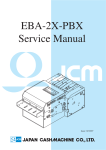
OPERATION AND SERVICE GUIDE
MEI
TRC Series Coin Changers
TRC
TRC
TRC
TRC
6000/6010
6510
6512
6800
1 Table of Contents
General Information
Overview .........................................
Product Summary ..........................
Specifications .................................
Unpacking the Changer .................
Warranty Information ....................
Installation ......................................
Checklist ..........................................
2
2
2
3
4
4
5
Changer Operation
Option Switches .............................
Interface Description ......................
Coin Acceptance .............................
Coin Separation ..............................
Coin Payout / Coin Return ..............
Change Making ...............................
Manual Dispensing of Coin ...........
Solenoid Operation ........................
6
7
11
12
12
12
13
13
Maintenance
Tuning ..............................................
Preparation (tuning) .......................
Tuning Coin Sets ............................
Routine Maintenance .....................
Cleaning ..........................................
Clearing Coin Jams ........................
13
13
14
15
15
16
Repair Policy
Owner's Responsibility ..................
Mars Electronics' Responsibility ...
Service .............................................
16
16
17
2 General Information
Overview
The TRC Operation and Service Guide
contains important information on
installing, operating and maintaining MEI
TRC Single Price, Micromech and MDB
Coin Changers.
To ensure continued peak performance after module
replacement, the changer features a special tuning mode
(see Tuning, page 13).
To obtain the best performance from your
coin changer, read through this manual
before installing and using the unit.
These coin changers are designed for use
in the following:
TRC-6000 - 110VDC Micromech Vending
Machine Controller (VMC) applications.
• 115 Volts DC + 20 Volts • 60 Hz 0.10
Amp continuous • 1.2 Amp peak (when
dispensing coins)
TRC-6010 - 24VDC Micromech Vending
Machine Controller (VMC) applications.
(12 pins) • 24 Volts DC + 20 Volts • 60 Hz
0.10 Amp continuous • 1.2 Amp peak
(when dispensing coins)
TRC-6010XV - 24VDC Micromech
Vending Machine Controller (VMC)
applications. (15 pins) • 24 Volts DC + 20
Volts • 60 Hz 0.10 Amp continuous • 1.2
Amp peak (when dispensing coins)
TRC-651x - 34VDC MDB applications.
• 34 Volts DC +20 Volts • 60 Hz 1.0 Amp
continuous • 3.2 Amp peak (when
dispensing coins)
TRC-6800 - Single Price Vendors. • 115
Volts AC +20 Volts • 60 Hz 0.10 Amp
continuous • 1.2 Amp peak (when
dispensing coins)
Product Summary
Electronic Coin Recognition
The TRC coin changer maximizes the
acceptance of valid coins, and minimizes
acceptance of slugs. As coins are inserted,
the TRC coin changer adjusts the coin
tracking parameters to maintain the
optimal operating range.
Figure 1: TRC Coin Changer
Physical Characteristics
Height: 370 mm (14.67") base to top of coin return lever
Width: 136 mm (5.35")
Depth: 76 mm (2.99")
Weight: 2.6 kg (5 lbs. 12 ozs.) in shipping container
Acceptance of U.S. coins
The TRC coin changers (Figure 1) are factory-tuned to
accept U.S. nickels, dimes, quarters, and dollar coins,
and can be re-tuned in the field to accept Canadian coins
(with the exception of the $2 coin).
Acceptance of nickels, dimes and quarters with
dollar coin accept/reject toggle switch
The changer is preset to accept U.S. dollar coins.
3 General Information
High or low quarter level
The level of quarter storage in the coin tube
is switch-selectable (see pages 6,7).
Table 1: Coin Tube Overflow
5¢
Tube
Low 25¢
Option
Switch
Set to
OFF
Position
Fewest Coin Payout
Coins of the highest denomination are
selected for change, enabling the changer
to pay out the coins.
Two Moving Parts for Coin
Acceptance and Separation
Valid coins enter the changer through a
solenoid-operated Accept Gate. If the
coin tube for the accepted coin is full, the
coin goes directly to the cash box. If the
coin tube is not full, a solenoid-operated
Separator Gate diverts the coin to the tube.
Note: Dollar coins, if accepted, are always
directed to the cash box.
Escrow
Single price applications dependent upon vend price.
Micromech and MDB application dependent on the VMC. Refer to the
vending machine manual for escrow
options, if applicable.
Price Setting
Single Price applications - located on the
control board of the changer.
Micromech and MDB application dependent on the VMC. Refer to the
vending machine manual for price setting
procedure.
Vend Price Range
Single price applications - 5¢ to $10.00
(all switches in an ON condition).
Micromech and MDB application dependent on the VMC.
Individual Coin Tube Overflow
Electronic sensors monitor the full/empty
status of the coin tubes. Each tube is
monitored individually to maximize coins
available for change.
25¢
Tube
10¢
Tube
Low 25¢
Option
Switch
Set to
ON
Position
Low
Sensor
Level
6-8
7-8
6-9
6-9
High
Sensor
Level
66-67
98-99
68-69
6-9
Easy Cleaning and Maintenance
No special tools are required for cleaning, or normal
field maintenance of the TRC coin changer. Refer to
page: 15.
Specifications
UL Approval
The TRC-60X0 Coin Changer is UL listed under file
number E 57869.
CSA Approval
The TRC-60X0C Coin Changer is CSA listed under file
number LR 47838.
Unpacking the Changer
Unpack the changer and immediately inspect it for any
possible shipping damage.
If the unit is damaged:
1) Return it to its original carton, along with packing
materials.
2) Notify the delivering carrier of damages and request
immediate inspection.
3) Send a letter of intent to file a claim to the delivering
carrier within 72 hours from the time of delivery.
4) Send a copy of the letter to the shipper.
5) Retain original carton and packing materials for
future use in shipping or transporting the changer.
Note: Only the consignee (the person or company
receiving the changer) can file a claim against the carrier
for concealed damages.
4 General Information
Warranty
Information
3) Set the option switches using a retractable ballpoint
pen or small screwdriver. Do not use a graphite
pencil point.
Once the unit has been inspected:
1) Record the serial and model numbers
from the label located on the side of the
changer.
2) Refer to these numbers whenever you
call your MEI dealer for information or
service.
Note: The option switches are located on either the
Control Board/Backplate Assembly or on the back of the
Flight Deck (TRC-6512 only).
The first three digits of the serial number
contain the manufacturing date code.
This code indicates the beginning of the
warranty period.
4) Set the vend prices on the changer (TRC-6800 only)
or vending machine.
Refer to vending machine manual for the exact
procedure for setting of the vend price(s).
For coin changers manufactured after
October 1989, the first two digits indicate
the week of manufacture, the third digit
indicates the year of manufacture.
Example:
A changer with serial number 05910000876
was manufactured in February of 1999.
Figure 2: Lowering the Acceptor Assembly
For coin changers manufactured before
November 1989, the first digit indicates the
year of manufacture; the next two digits
indicate the month of manufacture.
Example:
A changer with serial number 910-02705
was manufactured in October of 1989.
Installation
To install the TRC coin changer in a
vending machine, follow the step-by-step
instructions provided below. For more
detailed instructions, refer to the
Installation Guide shipped with the changer.
1) Lower the Acceptor Gate Assembly by
depressing both spring clips (Figure 2).
2) Tilt the Acceptor forward on the hinge.
5) Install the coin changer in the vending machine.
6) Adjust the vendor mounting screws to stand off a
minimum of 1/8".
7) Align the coin changer access holes in the changer
with the mounting screws. Tighten all screws to
secure the coin changer in place. The coin changer
must be vertical within +/- 3˚.
8) Apply power to the coin changer by connecting the
coin changer power plug to the power source.
9) Position or clamp the Main Harness so that it clears
the Coin Cup and Coin Return Lever.
10) Press the Acceptor/Gate Assembly back into the
housing until the spring clips engage.
11) Fill the coin tubes to the desired levels by inserting a
coin or coins into the loading slots located on the
coin tube front.
5 General Information / Changer Operation
...Then, to assure that the Coin Changer operates
correctly...
Test each dispense line through the service mode of
the VMC in sequence for 1 to 2 seconds. Dispense
switches are located on coin changer models
TRC-6800, TRC-6510 or TRC-6512. Refer to the
vending machine manual for dispense operation
using service mode (models TRC-6000 or
TRC-6010XV).
Figure 3: Manually Filling the Coin Tubes
Make sure a vend price is set. Do a test vend by
inserting more than the vend price. Make sure that
proper change is paid back and that there are
sufficient coins in the coin tubes to make proper
change. Replace dispensed coins in tubes. Refer to
vending machine manual for operation of setprice
mode.
Or
Manually deposit coins through the top of
the changer. Refer to the vending machine
manual to see if this second option is
available. (Refer to Table 1 for minimum
coin tube levels on page 3.)
Checklist
Check that...
The coin changer is flush against the
vendor wall.
The coin insert chute is aligned above
the center of the coin cup.
The coin changer reject and cash box
chutes are aligned with the vendor
reject and cash box chutes.
The vendor coin return lever should
fully depress coin changer return lever
but not touch when released.
Check escrow return by inserting coins of various
denominations to within 5¢ or more of vend price.
Request escrow return by depressing the return
button.
6 Changer Operation
Option Switches
Table 2: TRC60X0 Option Switches
Switch
Setting Function
1 (US/Canadian
acceptance
ON
Accepts US and Canadian
coins - if programmed
OFF
Accepts US coins only
ON
Stores 6 quarters for change
OFF
Stores 69 quarters for change
ON
Enables dollar coin acceptance
- if programmed
OFF
Disables dollar coin acceptance
ON
Accepts dollar coins without
quarters in 25¢ tube
OFF
Accepts dollar coin with
quarters in 25¢ tube
2 (Quarter tube
level)
3 (Dollar coin
acceptance)
Figure 4: TRC-60X0, TRC-6510 Option
Switch Location
4 (Dollar coin
acceptance 25¢ coin tube
dependency)
Table 3: TRC6510 Option Switches
Switch
Setting Function
1 (US/Canadian
acceptance)
ON
US and Canadian coin
acceptance
OFF
US coin acceptance
ON
Stores 6 quarters for change
OFF
Stores 69 quarters for change
ON
Enables dollar coin acceptance
- if programmed
OFF
Disables dollar coin acceptance
ON
Maximum acceptance
OFF
Maximum security
2 (Quarter tube
level)
3 (Dollar coin
acceptance)
4 (Acceptance
status)
Table 4: TRC6512 Option Switches
Switch
Setting Function
1 (Quarter tube
level)
ON
Stores 4 to 6 quarters for
change (LOW)
OFF
Stores 67 to 74 quarters for
change (HIGH)
ON
Accepts $ coins
OFF
Rejects $ coins
ON
Maximum security
OFF
Maximum acceptance
Figure 5: TRC-6512 Option Switch Location
2 (Dollar coin
acceptance)
3 (Acceptance
status)
7 Changer Operation
Table 5: TRC6800 Option Switches
Switch
Setting Function
1 (Dollar coin
acceptance)
ON
Accepts dollar coins
OFF
Rejects dollar coins
ON
Accepts US and
Canadian coins
OFF
Accepts US coins only
ON
Stores 6 quarters for
change
Stores 69 quarters for
change
AC/High level pulse bill
acceptor interface 115
VAC inputs, 9-pin
connector & power plug
interconnect
Low level pulse bill
acceptor interface +5
VDC, 9 & 18-pin
connectors
2 (US/Canadian
acceptance)
3 (Quarter tube
level)
OFF
4 (Bill acceptor
status)
ON
OFF
5 (Escrow)
ON
OFF
6 (Escrow
control)
ON
OFF
No excrow return
allowed (no monies
returned and credit is
held until a vend is
completed)
Escrow return allowed
(escrow mode
dependent on switch 6)
ETS (Escrow to Select)
For cigarette venders or
four-price venders (set
to vend on one price
only). Coin return can
be requested at any time
prior to making a
selection, or if the
selection is sold out
ETW (Escrow to Vend)
For standard single
price venders. Coin
return can be requested
at any time prior to
reaching vend price
Figure 6: TRC-6800 Option Switch
Location
Note: Escrow may not be paid if the VMC is set for No
Escrow Return. Refer to Vending Machine Manual for
operation, if applicable.
Single Price Interface
SINGLE PRICE INTERFACE ESCROW TO VEND
For an escrow to vend (standard) operation, a vend relay
is required in the vending machine. In the Escrow to
Vend (ETV) coin changer accumulated credit is compared
to the price set in the control logic of the coin changer as
coins are inserted. If adequate credit exists and if
required change is available, the control logic activates
the vend relay in the coin changer. The coin changer's
vend relay then connects the AC hot line to the vend
relay in the machine. The latching of this relay opens the
blocker contacts and enables the select switches.
Activation of a select switch causes the vend motor to
turn. The vend motor mechanically activates a carrier
switch which holds power on the motor and deactivates
the vend relay in the machine. The deactivation of the
vend relay cancels credit and initiates the changemaking cycle, if required.
SINGLE PRICE INTERFACE ESCROW TO SELECT
(for TRC-6800 changers with CIGARETTE
Switches)
For an escrow to select (cigarette) operation, a vend
relay is not required; however, an external sense circuit
is needed. This is normally supplied by the activation of
a select switch. In the Escrow to Select (ETS) changer,
accumulated credit is compared to the price set in the
control logic of the changer as coins are inserted.
The activation of a select switch causes a sense current
to flow in the coin changer. If adequate credit exists and
if required change is available, the control logic activates
the vend relay to connect the AC hot line to the select
switch. This causes the vend motor to turn. The vend
motor mechanically activates a carrier switch which
holds power on the motor and opens the blocker
contacts. The opening of the blocker contacts is then
sensed by the coin changer. The coin changer then
deactivates the vend relay, cancels credit and initiates
the change-making cycle, if required.
8 Changer Operation
Table 6: TRC6800 Power Plug Pins
PIN #
Description
1
117/24 VAC (Hot)
2
117/24 VAC (Neutral)
3
Vend Relay - Normally Open - Price #1 (Hot)
4
N/C
5
Exact Change - Normally Open (Neutral)
6
Blocker (Hot)
7
Vend Relay - Normally Closed (Hot)
8
Escrow to Select Option - not used in the
ETV condition
Micromech Interface
The Micromech interface transmits data to the external
VMC via its INTERRUPT and DATA lines. The controller
responds to these messages via its SEND line. These
three lines form the serial data link between changer
and controller. The VMC supplies power to operate the
changer via its four power lines. In addition, the VMC
has five control lines that authorize coin payout,
enable/inhibit coin acceptance, and reset the changer to
its standby condition. Refer to Figure 8 for power plug
pinout.
Micromech Electronics Operation Sequence
When a coin enters the mechanism, an "interrupt"
signal is sent on Pin #4 to inform the VMC that the
mechanism is ready to send credit information.
When the VMC receives this "interrupt" signal, it
signals the mechanism via a "send" signal on Pin #3.
This indicates to the mechanism that the VMC is
ready to accept "data".
When the mechanism receives this "send" signal, it
transmits a message on Pin #5 containing the
following data:
coin value - 5¢, 10¢, 25¢ or $1.00.
coin tube status - coin tube sensors are covered/not
covered.
coin direction - to coin tube or to cash box.
If a coin is rejected, or if there is a problem in the
mechanism, certain default messages are sent to the
VMC on the "data" line. They are as follows:
slug - coin entered but was not accepted (accept gate
did not open).
no strobe - coin was accepted but did not actuate
strobe (could indicate jam or strobe issue) dollar
coins rejected due to insufficient quarters in the coin
tube or sensor in the coin tube.
Figure 7: TRC6800 Power Plug
power up - indicates coin changer was just reset or
powered up.
9 Changer Operation
When sufficient credit has been
established in the VMC to enable a vend,
the VMC performs the changemaking logic
and sends logic +5V signal(s) to operate
the appropriate 5¢, 10¢ or 25¢ dispenser
solenoids in the mechanism for change
(if needed).
Micromech Interface Exceptions
The 15-pin Micromech interface is a
duplicate of the 12-pin Micromech
interface with two exceptions:
Pin #14 enables dollar coin dispense.
Not all VMC manufacturers utilize this
control line.
The 110VDC is referenced on pins 10
and 12; 24VDC is referenced on pins
13 and 15.
Note: Some manufacturers utilize a 24VDC
system exclusively. In those applications,
you may find that they will jump pins 10 to
13 and pins 12 to 15. This enhances the
installation for either TRC6010 or
TRC6010XV coin changers by using the
same socket.
Note: When the number of coins
introduced exceeds the highest price
programmed into the VMC, acceptance
will cease.
Table 7: Micromech Interface PINS and Descriptions
PIN #
Description
1
5VDC (Positive)
2
5VDC (Return)
3
Send (OV active)
4
Interrupt (OV active)
5
Data (OV active)
6
Accept Enable (OV active)
7
Quarter Dispense (OV active)
8
Dime Dispense (OV active)
9
Nickel Dispense (OV active)
10
110VDC or 24VDC
11
Reset Line (+5V active)
12
110VDC or 24VDC
13
24VDC (XV model only)
14
Unused on three tube model changers
15
24VDC (XV model only)
Micromech Interface Special Features
Accept Enable - Whenever the VMC sends the
"accept enable" signal on Pin #6, the mechanism
sends the "coin tube status" message. This can be
used while dispensing quarters to see when the
coins uncover the lower sensor. At that time, the
changer can dispense four more coins from that
tube. It can also be used by the VMC to determine if
the mechanism is operating by sending the "accept
enable" message every so often when no transaction
is taking place.
Reset (Pin #11) - this line enables the VMC to reset
the microprocessor of the mechanism in the event
there is a low power condition on the 5 volt line.
10 Changer Operation
Multi-Drop Bus Interface
Multi Drop Bus (MDB) Specifications
The TRC-6510 and TRC-6512 are configured as peripherals
to a VMC along with the bill validator, card reader, etc.
They rely fully on the VMC for a constant communication
that occurs during either idle or operational procedure.
The two lines that are utilized for this process are: TX
data line (Transmit Data) and RX data (Receive Data)
lines. These lines operate at a 9600 baud rate.
RX Data - enables the changer to accept coins,
informs the coin changer that it is ready to receive
data; the changer determines what change will be
dispensed.
TX Data - informs the microprocessor that a vend
cycle has been initiated, depending on what
denomination has been accepted.
This communication enables or disables acceptance
and coin dispensing during a transaction. The coin
changer simultaneously communicates with the VMC
regarding the type of coin that has been accepted and
the availability of change that may be required for the
next transaction. The routing of the coin, either to the
cash box or to coin tubes, is determined by the coin
changer. Figure 9 shows the power plug of the TRC-6510
or TRC-6512 coin changer.
Figure 8: TRC60X0 Power Plug
Table 8: TRC6510/6512 Power Plug Pins and
Descriptions
PIN #
Description
1
34VDC (Supply)
2
34VDC (Return)
3
No Connection
4
Master Receive
5
Master Transmit
6
Communication Common
Figure 9: TRC6510/TRC6512 Power Plug
11 Changer Operation
Changer Operation
General Operation
When coins are inserted into the coin
changer, they pass two electronic sensors
that measure coin diameter, metal content
and coin thickness. These measurements
are sent to the coin changer
microcomputer where they are compared
with predetermined coin acceptance
criteria.
If the coin does not meet the acceptance
criteria, the Accept Gate remains closed
and the coin is rejected. If it fits the criteria,
the coin is accepted. The Accept Gate
opens to allow the coin into the Separator
section. As it enters, it passes the Strobe
Sensor, which signals the microcomputer
to accumulate credit.
Each time a transaction occurs, the
microcomputer checks the status of the
upper coin tube sensors to see if the tubes
are full. If the tube corresponding to the
accepted coin is full, the Separator Gate
remains open and the coin is sent to the
cash box. If the appropriate tube can accept
coins, the Separator Gate closes and the
coin is routed to that tube.
Once a vend price has been reached, the
microcomputer checks the lower coin tube
sensors for change requirements. Coins of
the highest denomination available are
selected and the dispensers pay out the
change.
Coin Acceptance
When coins are inserted into the vending
machine, they enter via the Coin Cup of the
Acceptor/Gate Assembly. The coins hit two
snubbers that absorb the impact and allow
the coins to roll smoothly down the coin
ramp.
As the coins roll along the ramp, they pass two
electronic sensors embedded in the plastic behind the
coin path and Acceptor lid (Figure 10). The recognition
sensors measure coin diameter/metal content and coin
thickness. These values, which are sent to the changer's
microcomputer for analysis, determine whether the coin
will be accepted.
The microcomputer compares the information received
about the inserted coin to the predetermined coin
acceptance criteria stored in memory. If a coin falls
within the range of acceptable specifications, it is
accepted. The microcomputer sends a signal to the
Accept Gate, opening the Accept Gate and routing the
coin to the Separator section.
As the coin enters the Separator section, it passes the
Strobe Sensor. This electromagnetic coil signals the
microcomputer that a coin has been accepted.
The microcomputer then accumulates credit equal to the
value of the accepted coin, and closes the Accept Gate in
preparation for the next inserted coin.
Coin Rejection
Coins not meeting the acceptable specifications are
rejected. The Accept Gate remains closed, and the
rejected coin rolls off the top of the gate, down a ramp
to the reject chute, and drops into the coin return cup.
12 Changer Operation
Coin Payout/Coin Return
Coin payout can result from a transaction - escrow return
request, exact change condition, or change making from
a completed vend - or by manually reducing the
inventory levels in the coin tubes. Coins selected are
paid out by the Dispenser Assembly.
Whenever possible, escrow return is paid coin-for-coin
from the coin tubes. Escrow for coins that are not stored
for change is paid utilizing the highest denomination
coins available in the coin tubes.
In general, escrow return for dollar coins and bills is paid
in the highest denomination coins available from the
coin tubes. Payback is assured by the minimum coin
tube levels required for dollar coin and bill acceptance.
Note: If No Escrow Return is selected, there is no
minimum coin tube requirement for the acceptance of
dollar coins or bills. Consequently, full payback may not
be possible.
Figure 10: Coin Paths
Coin Separation
Accepted coins are directed to the coin
tubes or cash box by the Separator Gate.
Each time a transaction occurs, the
microcomputer checks the upper coin tube
sensors to determine whether or not the
tubes require coins. The Separator Gate is
directed accordingly.
If the appropriate coin tube is full (sensor
covered) or the coin is not stored for
change, the Separator Gate remains open.
This sends the coin directly to the cash box
via the cash box chute.
If the tube requires coins (sensor exposed)
and the coin is stored for change, the
changer microcomputer closes the
Separator Gate. This directs the coin down
a path that contains windows leading into
the coin tubes. As the coin reaches a
window of the correct diameter, it falls into
that window's tube.
Change Making
Change is paid out by the Dispenser Assembly utilizing
solenoid-operated slides. Each time a transaction
occurs, the changer microcomputer checks the status of
the lower coin tube sensors to see which coins are
available for change. Highest denomination coins are
paid back first. During a transaction, nickels, dimes and
quarters are paid out to the level of the lower coin tube
sensors. When used with a low level interface to a bill
acceptor, the TRC coin changer will not allow acceptance
of a dollar bill or coin if the lower dime and quarter
sensors are uncovered and more than seven nickels
would be required for change.
13 Changer Operation / Maintenance
Manual Dispensing
of Coins
Operating the manual dispense switches /
buttons reduces the level of coins in the
coin tubes by operating the proper
dispenser solenoid. Coins are dispensed
at a rate of two per second. The VMC of
the vending machine is responsible for
sending the dispense signal to the
TRC60X0 or TRC-651X coin changers.
Refer to the vending machine manual for
operation procedure for dispensing of
coins from changer.
Solenoid Operation
When a solenoid energizes, the upward
motion of its plunger compresses a spring
and draws the solenoid lever, which in turn
pushes a payout slide forward (Figure 11).
This loads a coin for payout. When the
solenoid de-energizes, the spring force
returns the plunger to its de-energized
state, which returns the solenoid lever,
returning the payout slide, paying out a
coin.
Tuning
TRC coin changers are factory preset to maximize valid
coin acceptance. However, periodic adjustments may be
required to correct differences that can occur when the
Acceptor/Gate Assembly and/or the Control
Board/Backplate Assembly are replaced. (No special
test equipment is required for tuning adjustments.)
In the Tuning Mode:
The coin changer is taught to recognize a set of coins.
As the coins are inserted through the Coin Cup, they are
placed into eight different tuning locations - two
locations per denomination [(nickel, dime, quarter, dollar,
Canadian and U.S.) Tokens on TRC-651x]. Two coins of
the same coinage may be used for acceptance.
The TRC-60x0 or TRC-6800 may also be taught to accept
a token in lieu of a coin.
Note: Dimensions and metal content will affect the
degree of success in using a token.
Depressing the Coin Return Lever during the tuning
procedure clears that tuning location.
After tuning, the changer switches to a calibration mode.
This mode serves as a fine-tuning function. Acceptance
will improve with the number of coins inserted.
Preparation - (In Vending Machine or Tester)
If tuning is required, perform these steps first:
1) Set one vend price to the highest programmable
price and activate the door switch for machine.
2) Turn the machine OFF.
3) Lower the Acceptor/Gate Assembly.
Figure 11: Solenoid Operation
14 Maintenance
4) Set the changer option switches as follows (if
applicable for your model coin changer):
ON
OFF
ON
ON
Tuning
Pins
U.S./ Canadian Acceptance
High 25¢ Sensor
$ Coin Acceptance
$ Coin Acceptance w/o 25¢
5) Short the set of tuning pins by touching both
simultaneously with the tip of a metal screwdriver/
tuning plug; MEI P/N 208240001 PAK 5. (See Figure
12 or Figure 13 on this page).
6) With the screwdriver/tuning plug still touching the
tuning pins, turn machine ON.
7) Remove the screwdriver/tuning plug when the
"normal" message appears on the display of the
machine.
8) Press the Acceptor/Gate Assembly back into position
until the spring clips engage.
The changer is now in the tuning mode. Now you are
ready to follow the Tuning Coin Sets.
Follow TUNING COIN SET listed below.
Figure 12: Shorting the Tuning Pins
TRC60X0, TRC6510, TRC6800
Tuning Coin Sets
Coin Set
Insert a US nickel
Insert a Canadian nickel
Insert a US dime
Insert a Canadian dime
Insert a US quarter
Insert a Canadian quarter
Insert a US dollar coin
Insert a Canadian dollar coin
Insert first token
Insert second token
Status
Rejected
Rejected (see Note 1)
Rejected
Rejected (see Note 1)
Rejected (see Note 1)
Rejected (see Note 1)
Rejected (see Note 1)
Rejected (see Notes 1 & 2)
(see Notes 2 & 3)
(see Notes 2 & 3)
Notes:
1) To skip the tuning of the coin depress the Coin Return
Lever.
Figure 13: Shorting the Tuning Pins
TRC6512 Only
2) Nickel solenoid will fire once on TRC-6800, TRC-6510
or TRC-6512.
3) TRC651x using level 3 MDB applications recognize
token acceptance.
15 Maintenance
To Calibrate the Coin Changer:
Drop fifteen coins of each denomination
into the coin changer following the tuning
order.
To Tune a Changer for One
Denomination only:
Depress the Coin Return Lever after each
insertion to move to the next denomination
coin. Or insert a second coin of the same
denomination rather than depressing the
Coin Return Lever.
Routine Maintenance
To Clean the Acceptor and Coin Ramp:
1) Swing the Acceptor lid diagonally upward and to the
right (see Figure 14). Hold the lid firmly so that it does
not snap back down.
2) Wipe the exposed coin ramp and inner surface of the
lid with a damp cloth. For problem cleaning, dampen
the cloth with water and mild, non-abrasive soap.
Note: When teaching proper use of a TRC-60X0C for
Canadian currency only, substitute a pre-1981 Canadian
nickel in the first step and use a post-1981 nickel in the
second step. All other models should use the post-1981
nickel. It will not accept the Canadian $2 coin.
Periodic routine maintenance improves the
performance and extends the optimum
working life of the coin changer. It can also
reduce the need for more costly repair or
replacement measures. Frequency of
routine maintenance will depend on the
environment and the number of vending
machine transactions.
Cleaning
Before cleaning, be sure to turn the
machine OFF and unplug the coin changer.
The TRC coin changer should be cleaned
only with warm water and a mild detergent
solution.
Caution
Never immerse the coin changer in
water.
Do NOT use solvents, steel wool,
scouring pads, or metal brushes for
cleaning.
Do NOT spray the coin changer with
any types of lubricant.
Since all coins roll down a common coin
ramp, heavy use can result in dirt buildup.
Figure 14: Cleaning the Acceptor Coin Ramp
To clean the Dispenser Slides:
1) Detach the Bottom Plate by removing the seven
Phillips head screws - one screw on each side (A), one
recessed screw on the back (B), and four screws on the
bottom of the changer (C) (see Figure 15).
2) Lift out the Bottom Plate and individual slides.
Clean them with a mild soap solution. Do not spray with
any type of lubricant.
16 Maintenance / Repair Policy
Once the slides are clean...
1) Set them on the Bottom Plate with the
numbered sides facing up into the coin
changer.
2) Align the plunger tabs with the bolts in
each side and seat the Bottom Plate.
3) Insert opposite screws (C of Figure 15)
first to hold the slides in place.
4) Install the remaining screws.
Clearing Coin Jams
If coins jam in the cash box chute, dislodge
them via the access holes at the rear of the
Dispenser Assembly.
!!!! WARNING !!!!
To avoid a possible shock hazard, use care when
performing any procedure that involves installing the
Control Board/Backplate Assembly. Route the Main
Harness and Dispenser Harness wires in such a way
that they cannot be pinched between the Backplate
and Housing.
Note: Check changer acceptance whenever the
Acceptor/Gate Assembly is replaced. If acceptance is
satisfactory, calibrate the unit by inserting 15 coins of
each denomination. If acceptance is poor, tune and
calibrate the unit following the instructions on page 13.
OWNER'S RESPONSIBILITY
Upon request, owner must show proof of purchase
when submitting equipment for service during the
warranty period. Owner will assume all freight charges
for shipment of equipment to an authorized service
center while under warranty, and to and from the service
center when outside the warranty period. Owner is
responsible for out-of-warranty repair expenses,
chargeable at prevailing rates set by authorized service
centers or in effect at service facilities. Complete written
information must be supplied to the authorized service
center for all items returned, including serial and model
number, and a description of the malfunction.
MEI RESPONSIBILITY
Figure 15: Clearing the Dispenser Slides
During the warranty period, MEI will repair or replace
any parts which fail to function properly because of
defects in material or workmanship. MEI shall not be
liable for any consequential damages as a result of
defects in material or workmanship. Damage due to
electrical overload, negligence, accidents, misuse,
abuse, vandalism, or an act of God is not covered by
MEI warranty. Any alteration of the product after
manufacture voids the warranty in its entirety.
The product to be repaired under warranty must be
delivered to an authorized service center. Repairs or
installation at the owner's location are not included in
the warranty.
17 Repair Policy
During the warranty period, MEI will
assume freight charges for return of the
owner's equipment from the closest
authorized service center via UPS or
common carrier.
NOTES:
SERVICE
______________________________________________________
______________________________________________________
______________________________________________________
______________________________________________________
For service information, contact MEI or any
MEI authorized service center. Parts and
labor that are MEI responsibility will be
provided without charge. Other service is at
owner's expense. For a parts manual,
service information, or the name of the
authorized service center nearest you, write
us at:
______________________________________________________
______________________________________________________
______________________________________________________
______________________________________________________
______________________________________________________
______________________________________________________
MEI
1301 Wilson Drive
West Chester, PA 19380
TECHNICAL SERVICE:
1-800-345-8172
CUSTOMER SERVICE:
1-800-345-8215
Check out our web site:
www.meiglobal.com
______________________________________________________
______________________________________________________
______________________________________________________
______________________________________________________
______________________________________________________
______________________________________________________
______________________________________________________
______________________________________________________
______________________________________________________
______________________________________________________
______________________________________________________
______________________________________________________
______________________________________________________
______________________________________________________
______________________________________________________
______________________________________________________
______________________________________________________
______________________________________________________
______________________________________________________
______________________________________________________
______________________________________________________
______________________________________________________
______________________________________________________
18
NOTES:
______________________________________________________
______________________________________________________
______________________________________________________
______________________________________________________
______________________________________________________
______________________________________________________
______________________________________________________
______________________________________________________
______________________________________________________
______________________________________________________
______________________________________________________
______________________________________________________
______________________________________________________
______________________________________________________
______________________________________________________
______________________________________________________
______________________________________________________
______________________________________________________
______________________________________________________
______________________________________________________
______________________________________________________
______________________________________________________
______________________________________________________
______________________________________________________
______________________________________________________
______________________________________________________
______________________________________________________
______________________________________________________
______________________________________________________
______________________________________________________
______________________________________________________
______________________________________________________
______________________________________________________
19
NOTES:
______________________________________________________
______________________________________________________
______________________________________________________
______________________________________________________
______________________________________________________
______________________________________________________
______________________________________________________
______________________________________________________
______________________________________________________
______________________________________________________
______________________________________________________
______________________________________________________
______________________________________________________
______________________________________________________
______________________________________________________
______________________________________________________
______________________________________________________
______________________________________________________
______________________________________________________
______________________________________________________
______________________________________________________
______________________________________________________
______________________________________________________
______________________________________________________
______________________________________________________
______________________________________________________
______________________________________________________
______________________________________________________
______________________________________________________
______________________________________________________
______________________________________________________
______________________________________________________
______________________________________________________
20
NOTES:
______________________________________________________
______________________________________________________
______________________________________________________
______________________________________________________
______________________________________________________
______________________________________________________
______________________________________________________
______________________________________________________
______________________________________________________
______________________________________________________
______________________________________________________
______________________________________________________
______________________________________________________
______________________________________________________
______________________________________________________
______________________________________________________
______________________________________________________
______________________________________________________
______________________________________________________
______________________________________________________
______________________________________________________
______________________________________________________
______________________________________________________
______________________________________________________
______________________________________________________
______________________________________________________
______________________________________________________
______________________________________________________
______________________________________________________
______________________________________________________
______________________________________________________
______________________________________________________
______________________________________________________