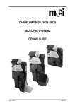
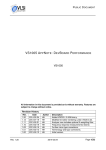
1
CashFlow® 130 Acceptor User Guide
The
®
CASHFLOW 130
ACCEPTOR
USER GUIDE
27360 G1
©, Mars, Inc., 1999
719521044
CashFlow® 130 Acceptor User Guide
Published by:
Mars Electronics International
Eskdale Road
Winnersh Triangle
Wokingham, Berkshire, RG41 5AQ
United Kingdom.
Internet: http://www.meiglobal.com
For further information on issues in other languages please write to the
Technical Communications Manager at the above address.
CashFlow® 130 Acceptor User Guide
©, Mars, Inc., 1999. All rights reserved
Except as permitted under the relevant local legislation, no part of this
publication may be copied, transmitted, transcribed, or distributed in any
form or by any means, or stored in a database or retrieval system, or
translated in any language (natural or computer), without the prior written
permission of Mars Electronics International.
Mars®, CashFlow® and the Mars Electronics International device are
registered trademarks.
©, Mars, Inc., 1999.
Mars Electronics International reserves the right to change the product or
the product specifications at any time. While every effort has been made
to ensure that the information in this publication is accurate, Mars
Electronics International disclaims any liability for any direct or indirect
losses (howsoever caused) arising out of use or reliance on this
information.
This document does not necessarily imply product availability.
Part Number
719521044
This edition (May 1999)
Printed in the United Kingdom.
ii
©, Mars, Inc., 1999
CashFlow® 130 Acceptor User Guide
CONTENTS
Safety Summary
2
Product Identification
4
Electrical Interfaces
5
Installation
6
Product Features
8
Configuration
10
Maintenance
18
Product Support
19
©, Mars, Inc., 1999
1
CashFlow® 130 Acceptor User Guide
SAFETY
Warning
Before cleaning, servicing, removing or replacing CashFlow® units,
ALWAYS SWITCH OFF or ISOLATE the ELECTRICITY SUPPLY to the
machine.
Caution
This guide is for use only by personnel trained to carry out electrical
installation.
Dangerous Environments
Do not operate the unit in the presence of flammable gasses or fumes, or
after the entry of fluid into the machine.
Disposal of Product
If necessary, always dispose of defective units according to local
regulations.
Conformance to International Standards
When installed and operated according to the instructions provided for
the particular unit, CashFlow® products meet the applicable national and
international safety standards for any country in which they are used.
Safety
All electrical connections to the product must be rated according to the
requirements for “Accessible SELV” circuits as defined in EN60335-1.
The product is therefore suitable for use in a class 2 (non-earthed or nongrounded) appliance.
Over current protection is not included in the product and should be
provided as part of the machine. The recommended fuse value at the
rated supply of 12V is: 1A slow blow (to EN60127)
Other protection methods may be used providing there over current
characteristics remain within the overall operating characteristics of the
above fuse.
When used in applications where compliance to BS EN60950: 1992 is
necessary, the host machine power supply must additionally meet the
requirements for SELV limited power supplies as defined in BS EN60950 For
these applications, the coin mechanism should be installed so that it is external
to any fire enclosure.
2
©, Mars, Inc., 1999
CashFlow® 130 Acceptor User Guide
DOCUMENT GUIDE
This document is for field engineers using the CashFlow® 130 product
produced by Mars Electronics International (MEI).
As an aid to using this document a series of symbols are used in the text
and have the following meanings:
F This indicates that a useful tip or word of advice is shown here.
0 Where this symbol is shown it indicates that a specific action is
called for to ensure a successful installation or set-up of the
product.
v
A note regarding the function to be carried out will
appear beside this symbol.
©, Mars, Inc., 1999
3
CashFlow® 130 Acceptor User Guide
PRODUCT IDENTIFICATION
®
CashFlow 130
Side Entry
CashFlow® 130
Top Entry
4
©, Mars, Inc., 1999
CashFlow® 130 Acceptor User Guide
ELECTRICAL INTERFACES
Green
Diagnostic
LED
Machine
Interface
Connector
Machine Interface - This provides power to the validator and carries the
coins inhibit signals from the machine and coin outputs to the machine.
©, Mars, Inc., 1999
5
CashFlow® 130 Acceptor User Guide
INSTALLATION
Installing or removing the CashFlow® product from your machine can be
done by following these simple instructions.
F When installing the CashFlow® 130-side entry product it will be fitted
to an MEI Front Plate and the following instructions will always apply.
®
F The mounting channel for the CashFlow
130 top entry product is
supplied by the machine manufacturer, and therefore some variations
may exist from machine to machine, however in principle these
instructions still apply.
CF 130 Front Entry Installation
Bosses
Retaining
Clips
0 Having ensured that the front plate has a firm location onto the
front of the machine, insert the side of the validator onto the two
round bosses at the rear of the front plate and push firmly
together until the two retaining clips are fully engaged.
0 Ensure the loom has not become disengaged or trapped during
the installation.
6
©, Mars, Inc., 1999
CashFlow® 130 Acceptor User Guide
CF 130 Top Entry Installation
Reject
Lever
Mounting
Points
Mounting
Point
F When mounted into a short channel the product must be fully
assembled and ready for use, with only the machine interface loom to
be connected.
0 The mounting points indicated must be firmly seated into the
channel and a gap of between 2-3 mm left between the reject
lever and the reject arm from the machine. This small gap will
ensure that the validator lid is able to fully close when the reject
button on the machine has been pressed and released.
©, Mars, Inc., 1999
7
CashFlow® 130 Acceptor User Guide
PRODUCT FEATURES
The CashFlow® 130 product has the flexibility to change certain settings
such as varying the coin-set that it handles.
These changes can be carried out using the rotary data switch and the
configuration switch, which are fitted to the CashFlow® 130 product. The
following pages show how, with the use of these switches, coins/tokens
can be inhibited or enabled, either a new individual token or a group of
tokens selected and the machine output mode changed.
In addition to these two switches there is a green diagnostic LED which
signifies if any changes you make have been successfully actioned or
not.
Green Diagnostic
LED
Rotary
Data Switch
Configuration
Switches
Coin/Token Acceptance
When the product is successfully mounted you will need to confirm that it
is set up correctly to accept good coins/tokens and direct them to where
you want them to go.
First things first
0 Press and release the reject button on the machine. Confirm that
the lid on the front of the validator closes fully when the reject
button is released. If it does not close fully the validator cannot
function properly.
0 Test that power is on by checking that the green LED on the front
of the validator is illuminated, it will flash off once when the reject
lever is pressed.
8
©, Mars, Inc., 1999
CashFlow® 130 Acceptor User Guide
Testing for Acceptance
0 Insert into the machine a selection of all the coins/tokens shown
on the validator label. The LED flashing off once will indicate
acceptance of each one, and if the coin/token is outside of the
programmed window it will flash off twice. If the LED flashes three
times this indicates that the validator 4th sensor has rejected the
coin/token. Should the LED flash off four times this indicates
either a hardware or software inhibit is being applied.
0 If further help is required then consult the Operators Handbook
for the product or contact either your distributor or local MEI
office.
COAS KIT
The CashFlow® 130 may be fitted with a COAS kit (coin on a string).
This is usually factory fitted and is only available on top entry products.
The kit consists of a small circuit board and a paddle fitted to the entry
components. When a coin is used with a string attached, the paddle is
caught and the circuit detects the movement. This results in coins being
inhibited.
F- ALARM
For German cigarette vending a link is set to allow an alarm output via
the F inhibit line (host machine interface connector pin 4). This is active
for approximately 500ms when an alarm condition is detected.
For other applications the link is made so that the F inhibit line is an input
from the host machine to allow a direct hardware inhibit.
Note: when the F alarm link is made the all inhibit input from the host
machine will continue to inhibit all coins, including the F coin.
©, Mars, Inc., 1999
9
CashFlow® 130 Acceptor User Guide
CONFIGURATION
Configuration Settings
The 4 way teach switches can be set up as shown below to configure the
product.
Switch Switch Switch Switch
1
2
3
4
OFF
ON
X
X
X
X
X
X
X
X
X
X
X
OFF
OFF
ON
OFF
ON
ON
ON
ON
OFF
X
X
OFF
ON
OFF
ON
ON
OFF
OFF
ON
OFF
X
X
ON
OFF
OFF
ON
OFF
ON
ON
ON
OFF
Mode Selected
Alarm Disabled
Alarm Enabled
Machine Interface Type
Inhibit Coin/Token Teach
Enable Coin/Token Teach
Self Teach a Token to Channel 0
Self Teach a Token to Channel 1
Discriminator Node ID Select
Fraud Defence Teach, Channel 0
Normal Operation
Normal Operation
Rotary
Switch
position/s
required
X
X
C-F
C-F
0-F
E-F
E-F
0-6
E-F
X
X
Diagnostic LED
0 The LED will illuminate to indicate that the product
is powered up, and in addition will give various
sequences of flashes to confirm the acceptance or rejection
status of coins/tokens.
F LED Flash Sequence:
F Constantly ON
Validator Power On.
1 Flash
Coin accepted / Reject lever pressed.
2 Flashes
Coin not recognised and rejected.
3 Flashes
Coin rejected by validator 4th sensor.
4 Flashes
Coin recognised but not accepted due to inhibit
setting.
10
©, Mars, Inc., 1999
CashFlow® 130 Acceptor User Guide
Using the Rotary Data Switch and Configuration Switches
Rotary Data Switch
The rotary data switch is used in conjunction with the
configuration switches. By pointing the arrow in the
middle of the switch, using a fine screwdriver, data
can be entered into the product. In Normal Operation
mode, the position of the arrow is not critical to
correct operation.
Configuration Teach Switches
These switches can be set to a series of positions, which enable the
product configuration to be changed.
When teach modes are to be entered first SWITCH
POWER OFF to the unit, or Un-intended action could be
set.
The example given here, with both the rotary data switch
and the configuration switch settings is to enable channel 3 in the coin
set.
F Wherever in the examples that follow the switch is shown as hatched
Grey (usually switch 1) it indicates that it does not matter if the switch
is in the ON or OFF position. Switch 1 only features in the settings for
Alarm Enable when it must be in the ON position. When it is in the
OFF position the Alarm function is NOT active.
0 After making any changes the
configuration switches 2, 3, and 4
MUST always return to either of the
Normal Operation positions shown
here, before the changes are
implemented.
To Turn ON or Turn OFF the Alarm
If switch one is set to OFF, the
alarm feature will be disabled. If
set to ON the alarm will be reactivated. Power to the validator
can remain ON while the alarm feature is being set, thus the LED will
continue to be lit at all times.
©, Mars, Inc., 1999
11
CashFlow® 130 Acceptor User Guide
Product Configuration - Inhibiting coins or tokens
Example:- To inhibit channel 2 (the 5p coin) on your validator follow these
simple steps.
Channel Inhibit
ON
1
2
3
Set switches 2, 3 and 4
as shown here.
4
1.
Switch Validator Power OFF.
ON
1
Set 4 Way Switches to Inhibit Teach.
2
2.
3
4
3 4 5 6
B C D
F 0 1
2
3.
E
Set Rotary Switch Dial to the appropriate channel.
(Channel No. 2 for the 5p in this instance).
7 8 9 A
5.
Set switches 2, 3 & 4 to ON. (LED will stop flashing and
stay on). The Rotary Switch settings can be left
unchanged.
2
3
4
6.
12
ON
Switch Validator Power ON (LED will flash).
1
4.
The chosen coin is now inhibited and the product is
END ready for normal operation. For each additional channel
to be inhibited repeat process from 1 above.
©, Mars, Inc., 1999
CashFlow® 130 Acceptor User Guide
Product Configuration Enabling Coins or Tokens
Example: - To enable channel 2 (the 5p coin in this instance) on your
validator follow these simple steps.
Channel Enable
ON
1
2
3
Set switches 2, 3 and 4
as shown here.
4
1.
Switch Validator Power OFF.
ON
1
Set 4 Way switches to Enable Teach.
2
3
2.
4
3 4 5 6
B C D
F 0 1
2
3.
E
7 8 9 A
4.
Switch Validator Power ON (LED will flash).
2
3
4
6.
ON
1
5.
Set Rotary Switch Dial to the appropriate channel.
(Channel No. 2 for the 5p in this instance).
Set switches 2, 3 & 4 to ON.
(LED will stop flashing and stay on).
The Rotary Switch settings can be left unchanged.
The chosen coin is now enabled and the product is
END ready for normal operation. For each additional channel
to be enabled repeat process from 1 above.
©, Mars, Inc., 1999
13
CashFlow® 130 Acceptor User Guide
Product Configuration –
Self teaching a new token, channel 0
Example: - To Teach a Token (with standard window limits) into channel
0 follow these simple steps.
LED Flash Codes for Tokens:
Channel Enable
2 flashes = No activity detected (for last 30 seconds)
ON
1
3 flashes = Insufficient Tokens (10 min.)
2
3
Set switches 2, 3 and 4
as shown here.
5 flashes = Token thickness outside allowable limits
4
6 flashes = Token diameter outside allowable limits
7 or 8 flashes = Token material outside allowable limits
1.
Switch Validator Power OFF.
on
1
Set 4 Way switches to Token Teach.
2
2.
3
4
F 0 1
3 4 5 6
B C D
E
2
3
Set Rotary Switch Dial to position F
(standard window limits)
(Position E will teach narrow token window limits).
7 8 9 A
5.
Drop between 10 and 20 Tokens.
6.
Return switches to Normal Operation. (LED should
stop flashing and stays on to indicate a successful
change). If the LED continues to flash this indicates
failure to teach the token.
If needed repeat the process from step 1.
ON
Switch Validator Power ON (LED will Flash).
1
4.
2
3
4
7. END
14
Token successfully taught & programmed into
Channel 0.
©, Mars, Inc., 1999
CashFlow® 130 Acceptor User Guide
Product Configuration – teaching a new token, channel 1
Example: - To Teach a Token (with standard window limits) into channel
1 follow these simple steps.
LED Flash Codes for Tokens:
Channel Enable
2 flashes = No activity detected (for last 30 seconds)
ON
1
3 flashes = Insufficient Tokens (10 min.)
2
3
Set switches 2, 3 and 4
as shown here.
5 flashes = Token thickness outside allowable limits
4
6 flashes = Token diameter outside allowable limits
7 or 8 flashes = Token material outside allowable limits
1.
Switch Validator Power OFF.
ON
1
Set 4 Way switches to Token Teach.
2
3
2.
4
B C D
3 4 5 6
3.
F 0 1
2
E
Set Rotary Switch Dial to position F (standard window
limits). (Position E will teach narrow token windows).
7 8 9 A
5.
Drop between 10 and 20 Tokens.
6.
Return switches to Normal Operation. (LED should
stop flashing and stays on to indicate a successful
change). If the LED continues to flash this indicates a
failure to teach the token. If needed repeat the
process from step 1.
ON
Switch Validator Power ON (LED will Flash).
1
4.
2
3
4
7. END
Token successfully taught & programmed into
Channel 1.
©, Mars, Inc., 1999
15
CashFlow® 130 Acceptor User Guide
Product Configuration –
Changing the machine output mode
To change the coin output interface to Fixed Binary Coded Output (BCO)
use these simple steps. For BCO mode set the rotary data switch to
position C, to D for Fixed Parallel mode and F for Automatic mode.
v
NOTE: The product will normally be supplied in Parallel
mode.
Example:- To set mode to Binary Coded Output
1.
Switch Validator Power OFF.
ON
1
Set 4 Way switches to Output Mode Teach.
2
3
2.
4
3 4 5 6
B C D
F 0 1
2
3.
E
Set Rotary Switch Dial to appropriate position.
(In this example Position C).
7 8 9 A
5.
Set switches 2, 3 & 4 to ON. (LED will stop flashing
and stay on). Leave the Rotary Switch settings as
they are.
ON
Switch Validator Power ON (LED will Flash).
1
4.
2
3
4
6.
16
END
Product is now ready for use with the chosen machine
interface.
©, Mars, Inc., 1999
CashFlow® 130 Acceptor User Guide
Product Configuration - Fraud Defence Teach
This feature allows a fraudulent coin to be taught to channel 0 of the
validator so that it can recognise it as a slug and can then reject it.
F 0 1
2
3
3 4 5 6
2
Set switches 2, 3 and 4
as shown here.
E
B C D
ON
1
Enable Fraud Defence
7 8 9 A
4
This feature requires 3 steps:
v
1. Teach the fraudulent coin/token as you would a token into
channel 0, as shown on page 13.
v
2. Set 4 way teach switches as shown in the example below to
identify the channel as a slug.
v
3. Enable channel 0, as shown on page 12.
1.
Switch validator power OFF.
ON
1
2
Set 4 way teach switches to enable fraud defense.
3
2.
4
Set rotary data switch to position E.
ON
7 8 9 A
1
2
4.
3 4 5 6
B C D
F 0 1
2
3.
E
Switch Validator power ON (LED will flash).
3
4
5.
LED stops flashing and stays on to indicate
successful change.
6. END
Fraud successfully taught into channel 0. The
Validator will now reject taught fraud coin the next
time it is seen.
©, Mars, Inc., 1999
17
CashFlow® 130 Acceptor User Guide
MAINTENANCE
F The practical maintenance that can be carried out is limited to
cleaning the areas of the Validator that the coins travel through, and
the replacement of the coin entry liner if it becomes worn. All other
servicing is carried out through your distributor.
The cleaning should be carried out on a regular basis of at least once a
month, but, if you have to visit the validator outside of that routine, it is
worth while doing it then as well.
The shaded areas shown below, plus the back of the reject cover, are
those to be cared for.
Unscrewing the coin entry moulding at the top of the validator accesses
the coin entry liner. The coin entry liner can then be eased off with the aid
of a fine screwdriver, and a replacement slid into place.
0 Suitably trained personnel must only carry out cleaning and
maintenance.
0 Cleaning must only be carried out after power has been removed
from the product.
0 Never use a cleaner containing solvents, scrapers or abrasive
materials.
0 Never apply water or cleansers directly onto the product. Always
apply them to a clean cloth first, and not too liberally, so that the
cloth used is only moist.
Coin Entry
Liner
Coin Entry
Moulding
Screw
Areas to
Clean
18
©, Mars, Inc., 1999
CashFlow® 130 Acceptor User Guide
PRODUCT SUPPORT
In addition to the MEI offices around the world, an international
network of Distributors and Approved Service Centres can offer you
technical support and other services as well.
These services include repairs, re-programming of your CashFlow®
products with new coinsets, replacing damaged modules, and the
supply of a range of spare parts.
GREAT BRITAIN
MARS ELECTRONICS
INTERNATIONAL
ESKDALE ROAD
WINNERSH TRIANGLE
WOKINGHAM
BERKSHIRE, RG41 5AQ
TELEPHONE: 0118 - 9697700
FACSIMILE: 0118 - 944612 MARS
UNITED STATES
MARS ELECTRONICS
INTERNATIONAL
1301 WILSON DRIVE
WEST CHESTER
PA 19380
TELEPHONE: 610 - 4302500
FACSIMILE: 610 - 4302694
AUSTRALIA
MARS ELECTRONICS
INTERNATIONAL
302 PARRAMATTA ROAD
AUBURN
NEW SOUTH WALES, 2144
TELEPHONE: 2 - 97375390
FACSIMILE: 2 - 97375399
CANADA
MARS ELECTRONICS
INTERNATIONAL
37, HOLLAND DRIVE
BOLTON
ONTARIO, L7E 5S4
TELEPHONE: 416 - 239 - 2782
FACSIMILE: 416 - 239 - 3322
FRANCE
MARS ELECTRONICS
INTERNATIONAL
BOULEVARD DES CHENATS - BP 7
45550 ST. DENIS DE L'HOTEL
TELEPHONE: 2 - 38 - 59 - 6534
FACSIMILE: 2 - 38 - 59 - 6838
GERMANY
MARS ELECTRONICS
INTERNATIONAL
INDUSTRIERING 17 A
41751 VIERSEN
TELEPHONE: 02162 - 9560
FACSIMILE: 02162 -
ITALY
MARS ELECTRONICS
INTERNATIONAL
27011 BELGIOIOSO (PV)
VIALE DANTE, 40
TELEPHONE: 0382 - 979313
FACSIMILE: 0382 - 970790
JAPAN
MARS ELECTRONICS
INTERNATIONAL
A DIVISION OF MASTER FOODS
LTD.
3F MUSASHI-KOSUGI TOWER
PLACE
403 KOSUGIMACHI 1-CHOME
NAKAHARA-KU, KAWASAKI-SHI
KANAGAWA-KEN 211
TELEPHONE: 44 - 712 - 1315
FACSIMILE: 44 - 712 - 1439
SPAIN
MARS ELECTRONICS
INTERNATIONAL
M.a DE MOLINA, 40-3a
28006 MADRID
TELEPHONE: 1 - 590 - 8782
FACSIMILE: 1- 590 - 8755
SWITZERLAND
MARS ELECTRONICS
INTERNATIONAL
CH. PONT-DU-CENTENAIRE 109
PLAN-LES-OUATES
P.O. BOX 2650
1211 GENEVA 2
TELEPHONE: 22 - 8840505
FACSIMILE: 22 - 8840504
©, Mars, Inc., 1999
19
Helping you deliver
Representetive