1
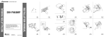
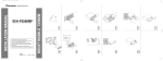
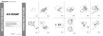
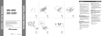
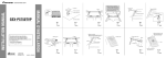
1. Auto-equalizing mike jack
Pull the auto-equalizing mike jack out of the
console box, so that the mike can be plugged
in or pulled out even after this unit has been installed.
19. Connecting cords with RCA
pin plugs (sold separately)
9. Subwoofer output
(SUBWOOFER OUTPUT)
20. Power amp
(sold separately)
10. Rear output (REAR OUTPUT)
1m
2. Antenna jack
15 cm
3. This Product
4. IP-BUS input (Blue)
20. Power amp
(sold separately)
15 cm
11. Front output
(FRONT OUTPUT)
5. IP-BUS cable
20. Power amp
(sold separately)
15 cm
6. Multi-CD player
(sold separately)
1m
21. Blue/white
To system control terminal of the power amp or
Auto-antenna relay control terminal (max. 300 mA
12 V DC).
7. Power box
22. System remote control
8. Power box cord
Install the power box cord
securely so that the cord can not
be easily pulled out.
23. Front speaker
12. Yellow/black
If you use a cellular telephone,
connect it via the Audio Mute
lead on the cellular telephone. If
not, keep the Audio Mute lead
free of any connections.
+
+
≠
≠
24. White
23. Front speaker
+
≠
≠
25. White/black
31. Green
13. Yellow
To terminal always supplied with
power regardless of ignition
switch position.
14. Fuse holder
15. Red
To electric terminal controlled by
ignition switch (12 V DC)
ON/OFF.
16. Fuse resistor
17. Orange/white
To lighting switch terminal.
16. Fuse resistor
30. Rear speaker
30. Rear speaker
35. Subwoofer
18. Black (ground)
To vehicle (metal) body.
36. With a 2 speaker system, do not
connect anything to the speaker leads
that are not connected to speakers.
26. Gray
+
28. Left
27. Gray/black
23. Front speaker
29. Right
33. Violet
+
+
≠
≠
32. Green/black
23. Front speaker
34. Violet/black
+
+
≠
≠
+
+
≠
≠
30. Rear speaker
30. Rear speaker
35. Subwoofer
37. Perform these connections when using
a different amp (sold separately).
Fig. 13
±≥ qJA«