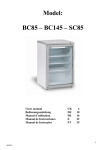
1
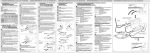
SISTEMA RGBW QUICK QUICK RGBW SYSTEM QCC-LCS TP DMX CONTROL DEVICE QCC-SPT DMX DMX512 MANAGEMENT DEVICE QCC-PLT 300 QUICK RGBW SYSTEM MANAGEMENT DEVICE QCC-DRV CH4 DRIVER FOR RGBW DOWNLIGHTS QCC RGBW RGBW DOWNLIGHTS REV 001a IT Manuale d’uso e manutenzione DISPOSITIVO DI GESTIONE DEL SISTEMA RGBW QUICK EN Manual of use and maintenance QUICK RGBW SYSTEM MANAGEMENT DEVICE FR Mode d’emploi et d’entretien DISPOSITIF DE GESTION DU SYSTÈME RGBW QUICK DE Benutzerhandbuch und Wartung STEUERGERÄT VOM SYSTEM RGBW QUICK ES Manual de uso y mantenimiento DISPOSITIVO DE CONTROL DEL SISTEMA RGBW QUICK QCC-LCS TP DMX CONTROL DEVICE QCC-SPT DMX DMX512 MANAGEMENT DEVICE QCC-PLT 300 QUICK RGBW SYSTEM MANAGEMENT DEVICE QCC-DRV CH4 DRIVER FOR RGBW DOWNLIGHTS QCC RGBW RGBW DOWNLIGHTS DISPOSITIVI PER LA REALIZZAZIONE DI UN SISTEMA RGBW COMPLETO • DEVICES FOR GETTING A COMPLETE RGBW SYSTEM • DISPOSITIFS POUR LA RÉALISATION D’UN SYSTÈME RGBW COMPLET • GERÄTE FÜR DIE REALISIERUNG EINES KOMPLETTEN RGBW SYSTEMS • DISPOSITIVOS PARA LA REALIZACIÓN DE UN SISTEMA RGBW COMPLETO Alimentazione Voltage Input 10÷30Vdc Output Segnale di comando DMX512 DMX512 command signal Input 4 segnali DMX 4 DMX signals Output Segnale di comando in DMX a QCC-PLT 300 command signal in DMX to QCC-PLT 300 Alimentazione Voltage Input 10÷30Vdc Input DMX512 o pulsanti DMX512 or push-buttons Output Segnale di controllo per QCC-DRV CH4 control signal for QCC-DRV CH4 Potenza gestibile Manageable power Fino a 300W a 24V Up to 300W to 24V Input Segnale di controllo da QCC-PLT 300 control signal for QCC-PLT CH4 Output Corrente costante 350mA max per ogni colore, per pilotare i faretti QCC RGBW 350 mA max constant current for each colour, to drive the QCC RGBW downlights Input Corrente costante 350mA max per ogni colore da QCC-DRV CH4 350 mA max constant current for each colour from QCC-DRV CH4 Power 6W max (tutti i colori accesi al massimo dell’intensità) 6W max (all colours ON at maximum intensity) QCC-LCS TP QUICK CONTROL COLOR LIGHT COLOR SELECTOR - TOUCH PANEL Dispositivo di comando DMX DMX control device QCC-SPT DMX QUICK CONTROL COLOR - SPLITTER DMX Dispositivo di gestione del segnale di comando DMX512 DMX512 management device QCC-PLT 300 QUICK CONTROL COLOR - PILOT 300 WATT Dispositivo di gestione del sistema RGBW Quick RGBW system management device QCC-DRV CH4 QUICK CONTROL COLOR - DRIVER CHANNELS 4 Driver per faretti RGBW RGBW downlights driver QCC RGBW DOWNLIGHT Faretti RGBW (vari modelli) Downlights RGBW (different models) • Alcuni di questi prodotti sono citati nel presente manuale • Some of these products are mentioned in this manual • certains de ces produits sont mentionnés dans ce manuel • einige der Produkte werden im vorliegenden Handbuch genannt • algunos de estos productos son mencionados en el presente manual QCC-PLT 300 - REV001A IT PRECAUZIONI ED AVVERTENZE La messa in funzione e la manutenzione dell’apparecchiatura deve essere effettuata da personale qualificato. Rispettare le prescrizioni riportate nel seguente manuale e le norme applicabili alla costruzione elettrica, in modo da garantire il corretto funzionamento dell’ apparecchiatura e la sicurezza delle persone e dell’ambiente. Il prodotto modificato o manomesso perde la garanzia del costruttore e la certificazione , e può presentare problemi di sicurezza per le persone e per l’ambiente. GB CAUTIONS AND WARNING Using and servicing the dimmer pack is restricted to qualified personnel. Follow the instructions in this manual and all the relevant electrical codes. This will ensure the device’s proper operation and the safety of people and the environment. Tampering with the device will void the Manufacturer’s Warranty and the Certification, and may lead to safety issues for people and the environment. FR PRECAUTIONS ET AVERTISSEMENT La mise en fonction et l’entretien de l’équipement doit être effectué par une personne qualifiée. Respecter les prescriptions reportées dans le manuel suivant et les normes applicables à la construction électrique, afin de garantir le fonctionnement correct de l’équipement et la sécurité de la personne et de l’environnement. Le produit modifié ou forcé perd la garantie du constructeur et la certification , et peut présenter des problèmes de sécurité pour les personnes et l’environnement. DE VORSICHTSMASSNAHMEN UND HINWEISE Die Inbetriebnahme und Wartung des Geräts muss von qualifiziertem Fachpersonal ausgeführt werden. Die im nachfolgend aufgeführten Vorschriften und Normen bezüglich elektrischer Gerätschaften müssen befolgt werden, Damit eine ordnungsgemäße Funktion des Geräts und die Sicherheit von Personen sowie der Umweltschutz garantiert werden können. Ein verändertes oder manipuliertes Produkt verliert seinen Anspruch gegenüber der Herstellerfirma und das -Zertifikat. Außerdem kann ein solches Gerät die Sicherheit von Personen gefährden sowie umweltschädlich werden. ES PRECAUCIONES Y ADVERTENCIAS La puesta en funcionamiento y el mantenimiento del equipo debe realizarse por personal calificado. Respete los requisitos indicados en el siguiente manual y las normas aplicables a la fabricación eléctrica para garantizar el funcionamiento correcto del equipo y la seguridad de las personas y del ambiente. El producto modificado o alterado pierde la garantía del fabricante y la certificación , y puede presentar problemas de seguridad para las personas y para el ambiente. 4 QUICK SPA QCC-PLT 300 - REV001A IT QCC-PLT 300 INDICE QUICK RGBW SYSTEM MANAGEMENT DEVICE Pag. 4 CARATTERISTICHE / INSTALLAZIONE / FUNZIONAMENTO Pag. 5 FUNZIONAMENTO - connessioni Pag.6SCHEMI DI COLLEGAMENTO Pag.7MANUTENZIONE / DATI TECNICI GB INDEX Pag. 8 CHARACTERISTICS / INSTALLATION / OPERATION Pag. 9 OPERATION - connections Pag.10 RGBW SYSTEM CONNECTION DIAGRAMS Pag.11 MAINTENANCE / TECHNICAL DATA FR P. P. P. P. DE S. S. S. S. ES SOMMAIRE 12 13 14 15 CARACTÉRISTIQUES / INSTALLATION / FONCTIONNEMENT FONCTIONNEMENT - connexion SCHÉMAS DE BRANCHEMENT DU SYSTÈME RGBW ENTRETIEN / CARACTÉRISTIQUES TECHNIQUES INHALTSANGABE 16 17 18 19 EIGENSCHAFTEN / INSTALLATION / BETRIEB BETRIEB - Anschlüsse ANSCHLUSSPLÄNE VOM SYSTEM RGBW WARTUNG / TECHNISCHE DATEN INDICE Pág. 20 CARACTERÍSTICAS / INSTALACIÓN / FUNCIONAMIENTO Pág. 21 FUNCIONAMIENTO - conexiones Pág.22 ESQUEMAS DE CONEXIÓN DEL SISTEMA RGBW Pág. 23 MANTENIMIENTO / ESPECIFICACIONES TÉCNICAS QUICK SPA 5 IT CARATTERISTICHE / INSTALLAZIONE QCC-PLT 300 - REV001A DESTINAZIONE D’USO • Il QCC-PLT 300 è destinato ad un utilizzo in ambiente nautico per il controllo del colore e la regolazione della luminosità di sorgenti luminose a LED RGBW. • Il QCC-PLT 300 deve essere utilizzato a temperatura regolata e ventilata e limitatamente esposto a polveri e umidità, per prevenire incendio. Non esporre questa unità alla pioggia o all’umidità. • Ogni altro uso è da considerarsi improprio e non prevedibile. DI UTILIZZARE IL PRODOTTO, LEGGERE ATTENTAMENTE IL PRESENTE MANUALE F PRIMA D'USO. IN CASO DI DUBBI CONTATTARE IL RIVENDITORE O IL SERVIZIO CLIENTI QUICK . ® LA CONFEZIONE CONTIENE: Dispositivo di gestione del sistema RGBW Quick® QCC-PLT 300 - condizioni di garanzia manuale d’uso e manutenzione. ELEMENTI TECNICI E DEFINIZIONI • dispositivo di comando: in questo specifico manuale si intende un’interfaccia utente che genera il segnale di comando (indicato nello schema di collegamento con dispositivo DMX 512). •sorgenti luminose a LED RGBW: in questo specifico manuale si intendono apparecchi illuminotecnici al cui interno abbiano un LED RGBW. Ognuno dei 4 canali è da pilotare in corrente costante. •segnale di comando: in questo specifico manuale è il segnale elettrico generato da un dispositivo di comando e che contiene le informazioni necessarie al QCC-PLT 300. •segnale di controllo: in questo specifico manuale è il segnale elettrico generato dal QCC-PLT 300 che contiene le informazioni necessarie per la gestione del sistema RGBW. DESCRIZIONE DEL PRODOTTO QCC-PLT 300 è un dispositivo elettronico che permette di gestire fino a 32 QCC-DRV CH4 utilizzando solo due cavi per fornire l’alimentazione ed il segnale di controllo. INSTALLAZIONE E MANUTENZIONE • Il dispositivo permette un rapido montaggio ad incastro su guide omega e va posto su una superficie verticale in modo da usufruire di una buona ventilazione naturale. • Il dispositivo deve essere posto in un quadro di distribuzione, opportunamente protetto, in modo da operare alle condizioni ambientali riportate nelle specifiche generali di utilizzo che non risulti accessibile a personale non qualificato. • Interrompere sempre la tensione di alimentazione durante le operazioni di installazione e manutenzione. • Le connessioni devono essere effettuate seguendo i criteri di buona esecuzione e scegliendo cavi di opportuna sezione e tipologia, adeguati alle condizioni ed ambiente d’uso. • Dopo avere effettuato le operazioni di installazione o manutenzione, verificare la corretta esecuzione del lavoro. • Dare alimentazione, ATTENZIONE A RISPETTARE LA POLARITÀ. 6 QUICK SPA FUNZIONAMENTO QCC-PLT 300 - REV001A IT QCC-PLT 300 Impianto, morsetti e cavi Il cablaggio dell’apparecchio, date le alte correnti in gioco, necessita di alcune prescrizioni: • la lunghezza massima dei cavi utilizzati per la parte di potenza non deve superare i 20mt. •Utilizzare cavi di sezione adeguata al carico applicato, limite del morsetto 2,5mm2, sia sull’alimentazione, sia sul cablaggio dei carichi. • La lunghezza massima dei cavi utilizzati per il BUS di segnale di controllo è 300 metri. Oltre i 200 metri richiedere un terminatore specifico NON EFFETTUARE MAI LE CONNESSIONI DELLE SORGENTI A LED DIRETTAMENTE SUI POLI DELL’ ALIMENTAZIONE. FUNZIONAMENTO Il QCC-PLT 300 riceve in ingresso un segnale di comando (DMX512) che converte in un segnale di controllo su due cavi destinato ad alimentare e controllare i QCC-DRV CH4 (driver Quicik® da utilizzare per alimentare le sorgenti luminose a LED RGBW). Questa sua caratteristica è quindi utilizzata per ridurre la quantità di cavi sull’impianto. Il QCC-PLT 300 può ricevere un segnale di comando da dispositivi DMX512 oppure da pulsanti: A) DMX512 Protocollo standard utilizzato in molti dispositivi di comando (touch panel e altre interfacce utente). Possibilità di gestire fino a 32 unità QCC-DRV CH4 e quindi 32 diversi ambienti luminosi. Per la parte di comando si distinguono due possibilità: •comando da un singolo punto: il dispositivo di comando va connesso direttamente al QCC-PLT 300 tramite porta DMX512. •comando da più punti: in questo caso è necessario aggiungere un QCC-SPT DMX che è un dispositivo in grado di gestire il segnale DMX512 proveniente da diversi dispositivi di comando. B) PULSANTI Attraverso quattro ingressi controllati da pulsanti a contatto pulito è possibile gestire il sistema RGBW come segue: •pulsante ingresso 1: - una pressione breve del pulsante all’ingresso 1 accende la luce all’ultimo valore di luminosità e colore impostati. - una pressione breve del pulsante all’ingresso 1 spegne la luce. - una pressione prolungata del pulsante all’ingresso 1 (>2sec) varia la luminosità in modo continuo da crescente a decrescente e viceversa, del colore selezionato. - quando è raggiunta la luminosità desiderata, rilasciando il pulsante all’ingresso 1, se ne memorizza il valore. •pulsante ingresso 2: - una pressione breve del pulsante all’ingresso 2 consente di variare il colore a step, selezionando tra: rosso, verde, blu, giallo, viola, azzurro, bianco. •pulsante ingresso 3: - una pressione breve del pulsante all’ingresso 3 consente di azionare uno scenario di cambio colore a miscelazione. - con lo scenario in azione, una pressione breve del pulsante all’ingresso 3 permette di regolare la velocità in 3 modalità di tempo di cambio colore: 10, 5, 2 secondi. - per uscire dalla modalità scenario è sufficiente una pressione breve di un qualsiasi pulsante escluso quello all’ingresso 3. •pulsante ingresso 4: - una pressione breve del pulsante all’ingresso 4 consente di attivare soltanto il canale White al massimo - una pressione breve del pulsante all’ingresso 4 spegne il canale White - una pressione prolungata del pulsante all’ingresso 4 (>2sec) varia la luminosità in modo continuo da crescente a decrescente e viceversa. QUICK SPA 7 IT SCHEMI DI COLLEGAMENTO DEL SISTEMA RGBW QCC-PLT 300 - REV001A A) Sistema RGBW comando da dispositivo DMX 10-30VDC QCC-PLT 300 SEGNALE DI CONTROLLO QCC-DRV SEGNALE DI COMANDO DMX QCC-DRV QCC-DRV FARETTI QCC DISPOSITIVO DMX512 B) Sistema RGBW comando da pulsanti 10-30VDC INPUT DA PULSANTI QCC-PLT 300 SEGNALE DI CONTROLLO PULSANTI CABLATI QCC-DRV QCC-DRV QCC-DRV FARETTI QCC 8 QUICK SPA MANUTENZIONE / CARATTERISTICHE TECNICHE QCC-PLT 300 - REV001A IT PULIZIA Per il dispositivo non sono previste operazioni particolari di pulizia, si consiglia eventualmente una pulizia superficiale della parte frontale mediante un panno umido non imbevuto di sostanze corrosive. Non usare liquidi direttamente sul prodotto, per evitare che possano entrare e procurare danni. LE OPERAZIONI DI PULIZIA DEVONO ESSERE ESEGUITE CON LA TENSIONE DI ALIMENTAZIONE NON PRESENTE. GARANZIA Il non rispetto delle prescrizioni del seguente documento fanno decadere la garanzia. CARATTERISTICHE TECNICHE MODELLO QCC-PLT 300 CARATTERISTICHE DI INGRESSO Alimentazione 10 ÷ 30 Vdc Corrente assorbita max 12,5 A DMX o da pulsanti a contatto pulito Input comando Potenza 150 W a 12 V / 300 W a 24 V CARATTERISTICHE GENERALI Temperatura esercizio da +5°C a +50°C Temperatura di stoccaggio da -40°C a + 70°C Umidità relativa 80% senza condensa Protezione contenitore IP 20 Materiale involucro Nylon autoestinguente Certificazioni Marcatura CE Contenitore per guida omega DIMENSIONI mm (inch) 112 (4 13/32) 58 (2 9/32) F F 90 (3 35/64) 87,5 (3 7/16) In caso di discordanze o eventuali errori tra il testo tradotto e quello originario in italiano, fare riferimento al testo italiano o inglese. Quick® si riserva il diritto di apportare modifiche alle caratteristiche tecniche dell’apparecchio e al contenuto di questo manuale senza alcun preavviso. QUICK SPA 9 EN CHARACTERISTICS / INSTALLATION QCC-PLT 300 - REV001A INTENDED USE • The QCC-PLT 300 is intended to be used in nautical applications to control and adjust the brightness of LED RGBW light sources. • For fire-prevention reasons, install the QCC-PLT 300 in a ventilated, controlled-temperature environment, protected from dust and humidity. Do not expose the dimmer pack to rain or humidity. • Any other use should be considered improper and unpredictable. THESE INSTRUCTIONS CAREFULLY BEFORE USING THE PRODUCT. IN CASE OF F READ DOUBT, CONTACT YOUR DEALER OR QUICK CUSTOMER SERVICE. ® THE PACKAGE CONAINS: Quick® RGBW system management device - conditions of warranty - the manual of installation and use. TECHNICAL ELEMENTS AND DEFINITIONS • Control device: in this specific manual, this is a user interface that generates the command signal (indicated in the connection diagram with DMX 512 device). •RGBW LED light sources: in this specific manual, these are lighting devices inside which there is a RGBW LED. Each of the four channels is to be driven in constant current. •Command signal: in this specific manual, this is the electrical signal generated by a control device and which contains the necessary information for the QCC-PLT 300. •Control signal: in this specific manual, it is the electrical signal generated by the QCC-PLT 300 and which contains the necessary information for the management of the RGBW system PRODUCT DESCRIPTION The QCC-PLT 300 is an electronic device that is used to manage up to 32 QCC-DRV CH4 by using just two wires for supplying power and the control signal. INSTALLATION AND MAINTENANCE • The QCC-PLT 300 can be easily mounted on a omega rail. Install the device on a vertical surface for better ventilation. • The device must be placed in a suitably protected distribution board so that it can operate under the environmental conditions indicated in the general specifications for use, and is not within reach of personnel who are not qualified. • Always disconnect the supply voltage during installation and maintenance operations. • Make the connections following the best practices, using cable of adequate type and size that are appropriate for the environment conditions. • Critically inspect your work immediately after installing or servicing the product. • Turn on the power, MAKE SURE THE POLARITY IS RIGHT. 10 QUICK SPA OPERATION QCC-PLT 300 - REV001A EN QCC-PLT 300 Wiring, terminals and cables Considering the high currents involved, a few precautions on wiring are in order: • the cables used for the power stage should be no longer than 20 m. •Use cables having an adequate cross-section (max. terminal size 2.5 mm2), both for connecting the power supply and wiring the devices. • The maximum length of the wires used for the control signal BUS is 300 metres. Beyond 200 metres a specific terminal is needed. DO NOT UNDER ANY CIRCUMSTANCES CONNECT THE LEDS DIRECTLY TO THE TERMINALS OF THE POWER SUPPLY. OPERATION The QCC-PLT 300 receives an input command signal (DMX512) which is turned into a control signal on two wires intended to power and control the QCC-DRV CH4 (which, in turn, will be connected to the RGBW LED light sources). This characteristic is therefore used to reduce the number of wires on the system. The QCC-PLT 300 can receive a command signal from DMX512 devices or from push-buttons: A) DMX512 Standard protocol used in many control devices (touch panels and other user interfaces). Up to 32 QCC-DRV CH4 units can be managed and, therefore, 32 different light environments. For the command section, there are two possibilities: •command from a single point: the control device is directly connected to the QCC-PLT 300 via the DMX512 port. •command from several points: in this case, it is necessary to add a QCC-SPT DMX, which is a device that can manage the DMX512 signal coming from different control devices. B) PUSH-BUTTONS By means of four inputs controlled by dry contact push-buttons, the RGBW system can be managed as follows: •input 1 push-button: - Briefly press the push-button at input 1 to turn on the light at the last brightness and colour value being set. - Briefly press the push-button at input 1 to turn off the light. - Press and hold the push-button at input 1 (>2 sec) to vary the brightness continuously from increasing to decreasing and vice versa, of the selected colour. - Once the desired brightness is reached, release the push-button at input 1 to save the value. •input 2 push-button: - Briefly press the push-button at input 2 to vary the colour at steps, choosing among: red, green, blue, yellow, violet, sky blue and white. •input 3 push-button: - Briefly press the push-button at input 3 to enable a mixing colour change scenario. - When the scenario is in operation, briefly press the push-button at input 3 to adjust the speed in 3 colour change time modes: 10, 5 and 2 seconds. - To exit the scenario mode, just briefly press any push-button except for the one at input 3. •input 4 push-button: - Briefly press the push-button at input 4 to enable only the White channel at the maximum - Briefly press the push-button at input 4 to turn off the White channel - Press and hold the push-button at input 4 (>2 sec) to vary the brightness continuously from increasing to decreasing and vice versa. QUICK SPA 11 EN RGBW SYSTEM CONNECTION DIAGRAMS QCC-PLT 300 - REV001A A) RGBW system control from DMX device 10-30VDC QCC-PLT 300 CONTROL SIGNAL QCC-DRV DMX COMMAND SIGNAL QCC-DRV QCC-DRV QCC DOWNLIGHTS DMX512 DEVICE B) RGBW system control from push-buttons 10-30VDC INPUTS FROM PUSH-BUTTONS QCC-PLT 300 CONTROL SIGNAL WIRED PUSH-BUTTONS QCC-DRV QCC-DRV QCC-DRV QCC DOWNLIGHTS 12 QUICK SPA MAINTENANCE / TECHNICAL DATA QCC-PLT 300 - REV001A EN CLEANING The device requires no special cleaning procedure. Clean the front using a damp cloth, avoiding corrosive substances. Do not apply liquids directly on the unit; they might penetrate and damage the device. DISCONNECT THE POWER SUPPLY BEFORE CLEANING THE UNIT. WARRANTY Failure to comply with the prescriptions below will void the Warranty. TECHNICAL DATA MODEL QCC-PLT 300 INPUT CHARACTERISTICS Power supply 10 ÷ 30 Vdc Power consumption max 12,5 A DMX or by clean-contact push buttons Control input Power 150 W to 12 V / 300 W to 24 V GENERAL Operating temperature from +5°C to +50°C Storage temperature from -40°C to + 70°C Relative humidity 80% non-condensing Housing protection IP 20 Casing material Self-extinguishing nylon Certifications CE marking Housing for omega rail DIMENSIONS mm (inch) 112 (4 13/32) 58 (2 9/32) F F 90 (3 35/64) 87,5 (3 7/16) In case of discordance or errors in translation between the translated version and the original text in the Italian language, reference will be made to the Italian or English text. Quick® reserves the right to modify the technical characteristics of the equipment and the contents of this manual without prior notice. QUICK SPA 13 FR CARACTÉRISTIQUES / INSTALLATION QCC-PLT 300 - REV001A CONDITIONS D’UTILISATION • QCC-PLT 300 est destiné à une utilisation dans un environnement nautique pour le contrôle et le réglage de la luminosité de sources lumineuses à LED RGBW. • Le QCC-PLT 300 doit être utilisé à température régulière et aérée et le moins possible exposé à la poussière et à l’humidité, afin de prévenir d’éventuels incidents. Ne pas exposer cette unité à la pluie ou à l’humidité. • Tout autre type d’utilisation est considéré impropre et non prévisible. D’UTILISER L’APPAREIL, LIRE ATTENTIVEMENT LE MODE D’EMPLOI SUIVANT. EN F AVANT CAS DE DOUTE CONTACTER LE REVENDEUR OU LE SERVICE CLIENT QUICK . ® L’EMBALLAGE CONTIENT: QCC-PLT 300 Dispositif de gestion du système RGBW Quick® - conditions de garantie - le mode d’installation et d’emploi. ÉLÉMENTS TECHNIQUES ET DÉFINITIONS • dispositif de commande: dans ce manuel spécifique, cela signifie une interface utilisateur qui génère le signal de commande (indiqué dans le schéma de branchement avec dispositif DMX 512). •sources lumineuses à LED RGBW: dans ce manuel spécifique, cela signifie des appareils d’éclairage équipés avec une LED RGBW. Chacun des quatre canaux doit être piloté à courant constant. •signal de commande: dans ce manuel spécifique, cela signifie le signal électrique généré par un dispositif de commande contenant les informations nécessaires au QCC-PLT 300. •signal de contrôle: dans ce manuel spécifique, cela signifie le signal électrique généré par le QCC-PLT 300 contenant les informations nécessaires pour la gestion du système RGBW. DESCRIPTION DU PRODUIT QCC-PLT 300 est un dispositif électronique qui permet de gérer jusqu’à 32 QCC-DRV CH4 en utilisant seulement deux câbles pour fournir l’alimentation et le signal de contrôle. INSTALLATION ET ENTRETIEN • L’appareil permet un montage encastré sur guide oméga rapide et est placé sur une surface verticale de manière à bénéficier d’une bonne ventilation naturelle. • Le dispositif doit être placé dans un tableau de distribution correctement protégé, de manière à fonctionner dans les conditions environnementales indiquées dans les spécifications générales d’utilisation, et inaccessible au personnel non qualifié. • Toujours couper la tension d’alimentation pendant les opérations d’installation et de maintenance. • Les connexions doivent être effectuées en suivant les critères de bonne exécution et en choisissant des câbles de section et typologie adaptées, appropriés aux conditions et à l’environnement d’utilisation. • Après avoir effectué les opérations d’installation ou d’entretien, vérifier l’exécution correcte du travail. • Donner l’alimentation, ATTENTION À RESPECTER LA POLARITÉ. 14 QUICK SPA FONCTIONNEMENT QCC-PLT 300 - REV001A FR QCC-PLT 300 Installation, bornes et câbles Le câblage de l’appareil, étant donné le haut courant en jeu, nécessite quelques prescriptions: • la longueur max des câbles utilisés pour la partie de puissance ne doit pas dépasser 20mt. •Utiliser des câbles de section adéquate à la charge appliquée, limite de la borne 2,5mm2, soir sur l’alimentation, soit sur le câblage des charges. • La longueur maximum des câbles utilisés pour le BUS du signal de contrôle est de 300 mètres. Au-delà de 200 mètres, demander une terminaison spécifique. NE JAMAIS EFFECTUER LES CONNEXIONS DES LED DIRECTEMENT SUR LES PÔLES D’ALIMENTATION. FONCTIONNEMENT Le QCC-PLT 300 reçoit un signal de commande en entrée (DMX512) qu’il convertit en un signal de contrôle sur les deux câbles destiné à alimenter et à contrôler les QCC-DRV CH4 (qui seront ensuite branchés à leur tour aux sources lumineuses à LED RGBW). Cette caractéristique est utilisée pour réduire la quantité de câbles sur l’installation. Le QCC-PLT 300 peut recevoir un signal de commande des dispositifs DMX512 ou bien des boutons: A) DMX512 Protocole standard utilisé dans beaucoup de dispositifs de commande (écran tactile et autres interfaces utilisateur) Possibilité de gérer jusqu’à 32 unités QCC-DRV CH4 et, par conséquent, 32 environnements lumineux. Pour la partie de commande, il existe deux possibilités: •commande à partir d’un seul point: le dispositif de commande doit être branché directement au QCC-PLT 300 via le port DMX512. •commande à partir de plusieurs points: dans ce cas, il est nécessaire d’ajouter un QCC-SPT DMX qui est un dispositif en mesure de gérer le signal DMX512 provenant de plusieurs dispositifs de commande. B) BOUTONS Il est possible de gérer le système RGBW comme suit au moyen de quatre entrées contrôlées par des boutons à contact libre de potentiel: •bouton entrée 1: - en appuyant brièvement sur le bouton à l’entrée 1, la lumière s’allume avec la dernière valeur de luminosité et de couleur réglée. - en appuyant brièvement sur le bouton à l’entrée 1, la lumière s’éteint. - en appuyant longuement sur le bouton à l’entrée 1 (>2 sec) la luminosité varie de manière continuelle de croissante à décroissante et vice-versa, dans la couleur sélectionnée. - lorsque la luminosité désirée est obtenue, la valeur se mémorise en relâchant le bouton à l’entrée 1. •bouton entrée 2: - appuyer brièvement sur le bouton à l’entrée 2 permet de faire varier la couleur par étape, en sélectionnant entre: rouge, vert, bleu, jaune, violet, bleu ciel, blanc. •bouton entrée 3: - appuyer brièvement sur le bouton à l’entrée 3 permet de générer un scénario de changement de couleurs mélangées. - appuyer brièvement sur le bouton à l’entrée 3 avec le scénario activé, permet de régler la vitesse en 3 modalités de vitesse de changement de couleur : 10, 5, 2 secondes. - pour sortir de la modalité scénario, il suffit d’appuyer brièvement sur n’importe quel bouton, sauf celui à l’entrée 3. •bouton entrée 4: - appuyer brièvement sur le bouton à l’entrée 4 permet d’activer uniquement le canal White au maximum - en appuyant brièvement sur le bouton à l’entrée 4, le canal White s’éteint. - en appuyant longuement sur le bouton à l’entrée 4 (>2sec) la luminosité varie de manière continuelle de croissante à décroissante et vice-versa. QUICK SPA 15 FR SCHÉMAS DE BRANCHEMENT DU SYSTÈME RGBW QCC-PLT 300 - REV001A A) Système RGBW commande à partir du dispositif DMX 10-30VDC QCC-PLT 300 SIGNAL DE CONTRÔLE QCC-DRV QCC-DRV QCC-DRV SIGNAL DE COMMANDE DMX DISPOSITIF DMX512 ENCASTERS A LED QCC B) Système RGBW commande à partir des boutons 10-30VDC ENTRÉE À PARTIR DES BOUTONS QCC-PLT 300 SIGNAL DE CONTRÔLE BOUTONS CÂBLÉS QCC-DRV QCC-DRV QCC-DRV ENCASTERS A LED QCC 16 QUICK SPA ENTRETIEN / CARACTÉRISTIQUES TECHNIQUES QCC-PLT 300 - REV001A FR NETTOYAGE Pour le dispositif aucune opération de nettoyage particulière n’est prévue, il est éventuellement conseillé un nettoyage superficiel de la partie frontal avec un chiffon humide non imbibé de substance corrosive. Ne pas utiliser de liquides directement sur le produit, afin d’éviter qu’ils puissent entrer et provoquer des dommages. LES OPÉRATIONS DE NETTOYAGE DOIVENT ÊTRE EFFECTUÉES AVEC LA TENSION DE RÉSEAU NON PRÉSENTE. GARANTIE Le non respect des précautions du document suivant font perdre la garantie. CARACTÉRISTIQUES TECHNIQUES MODELE QCC-PLT 300 CARACTERISTIQUES D’ENTREE Alimentation 10 ÷ 30 Vdc Courant absorbé max 12,5 A DMX ou par poussoirs à contact propre Entrée de la commande Puissance 150 W à 12 V / 300 W à 24 V CARACTERISTIQUES GENERALES Température exercice de +5°C à +50°C Température de stockage de -40°C à + 70°C Humidité relative 80% sans condensation Protection boîtier IP 20 Matériel Boîtier Nylon autoestinguente Certifications Marquage CE Boîtier Pour guide omega DIMENSIONI mm (inch) 112 (4 13/32) 58 (2 9/32) F F 90 (3 35/64) 87,5 (3 7/16) En cas de discordances ou d’erreurs éventuelles entre la traduction et le texte original en italien, se référer au texte italien ou anglais. Quick® se réserve le droit d’apporter des modifications aux caractéristiques techniques de l’instrument et au contenu de ce mode d’emploi sans aucun préavis. QUICK SPA 17 DE EIGENSCHAFTEN / INSTALLATION QCC-PLT 300 - REV001A GEBRAUCHSZWECK • Das QCC-PLT 300 ist für einen Gebrauch im Bereich der nautische bestimmt, um die Helligkeit von LEDRGBWLichtquellen zu steuern und zu regulieren. • Das Steuergerät QCC-PLT 300 muss bei geregelter Temperatur, belüftet und vor Staub und Feuchtigkeit geschützt installiert werden, um Bränden vorzubeugen. Diese Einheit darf Regen und Feuchtigkeit nicht ausgesetzt sein. • Jeder anderer Gebrauch ist nicht vorgesehen und daher als unangemessen zu betrachten. O R D E M G E B R AU C H DA S G E R ÄT M U S S D I E S E B E D I E N U N G S A N L E I T U N G F VAUFMERKSAM GELESEN WERDEN. BEI ZWEIFELN UND FRAGEN MUSS SICH AN DAS HANDELSUNTERNEHMEN ODER DEN KUNDENDIENST QUICK® GEWANDT WERDEN. DIE PACKUNG ENTHÄLT: QCC-PLT 300 Steuergerät vom System RGBW Quick® - Garantiebedingungen - Installationsund Benutzerhandbuch. TECHNISCHE BAUTEILE UND BEGRIFFSBESTIMMUNG • Steuergerät: in diesem Handbuch wird darunter das Benutzerinterface verstanden, das das Steuersignal erzeugt (angegeben auf dem Anschlussplan mit dem Steuergerät DMX 512). •LED RGBW Leuchte: in diesem Handbuch werden darunter die Leuchten mit LED RGBW verstanden. Alle vier Kanäle werden in Gleichstrom angesteuert. •Steuersignal: in diesem Handbuch wird darunter das elektrische Signal verstanden, das von einem Steuergerät erzeugt wird und die notwendigen Informationen für den QCC-PLT 300 enthält. •Kontrollsignal: in diesem Handbuch wird darunter das elektrische Signal verstanden, das von QCC-PLT 300 erzeugt wird und die notwendigen Informationen für die Steuerung vom RGBW System enthält. PRODUKTBESCHREIBUNG QCC-PLT 300 ist ein elektronisches Steuergerät, das die Steuerung von maximal 32 QCC-DRV CH4 erlaubt, wobei nur zwei Kabel für die Stromversorgung und die Übertragung vom Kontrollsignal erforderlich sind. INSTALLATION UND WARTUNG • Die Vorrichtung erlaubt eine schnelle Steckmontage auf Omega-Schienen und wird an einer senkrechten Fläche positioniert, um eine gute natürliche Belüftung zu gewährleisten. • Das Gerät muss an einer hinreichend geschützten Schalttafel installiert werden. Es muss sichergestellt werden, dass das Gerät unter den in den Spezifikationen angegebenen Umgebungsbedingungen läuft und für Unbefugte nicht zugänglich ist. • Während Installations- und Wartungsarbeiten muss die Spannungsversorgung immer unterbrochen sein. •Die Anschlüsse müssen den Kriterien einer ordnungsgemäßen Funktionsweise entsprechen und es müsse dafür geeignete Kabel mit passendem Querschnitt verwendet werden, die für die Bedingungen und den Verwendungsort geeignet sind. • Nach Abschluss von Installation oder Wartung muss die ordnungsgemäße Funktion geprüft werden. • Bei der Stromzufuhr MUSS DIE POLARITÄT BEACHTET WERDEN. 18 QUICK SPA BETRIEB QCC-PLT 300 - REV001A DE QCC-PLT 300 Anlage, Klemmen und Kabel Für die Verkabelung der Vorrichtung sind aufgrund des eingesetzten Starkstroms einige Vorschriften notwendig: : • Max. Länge der verwendeten Kabel der Leistung darf nicht mehr als 20 m betragen. •Kabel mit der angewendeten Last entsprechendem Querschnitt verwenden; Grenze der Klemme 2,5 mm 2 , sowohl an der Versorgung als auch an der Lastverkabelung. •Die Kabel, die für die Übertragung vom BUS-Kontrollsignal verwendet werden, dürfen maximal 300 m lang sein. Bei einer Kabellänge von mehr als 200 m ist eine spezielle Endklemme erforderlich. D I E L E D - L EU CH T E N D Ü R FE N N I E M A L S D I R E K T Ü B E R D I E VERSORGUNGSPOLE ANGESCHLOSSEN WERDEN. BETRIEB Das QCC-PLT 300 empfängt ein Steuersignal (DMX512), das an einem der beiden Kabel (Stromkabel und Signalkabel) der QCC-DRV CH4 in ein Kontrollsignal umgewandelt wird, die wiederum an die Leuchten LED RGBW angeschlossen sind. Mit dieser Installation wird die Anzahl der in der Anlage erforderlichen Kabel reduziert. Das QCC-PLT 300 kann ein Steuersignal von den Steuergeräten DMX512 erhalten oder von den Tasten: A) DMX512 Standardprotokoll, das von vielen Steuergeräten verwendet wird (Touchpanel und andere Benutzerinterfaces). Es können bis zu 32 Steuergeräte QCC-DRV CH4 und damit 32 Beleuchtungsanlagen gesteuert werden. Für die Steuerung gibt es zwei Möglichkeiten: •Ein-Punkt-Steuerung: das Steuergerät wird über die Schnittstelle DMX512 direkt an das QCC-PLT 300 angeschlossen. •Mehrpunkt-Steuerung: in diesem Fall muss auch ein QCC-SPT DMX installiert werden, das in der Lage ist, das DMX512 Signal zu verarbeiten, das von verschiedenen Steuergeräten übertragen wird. B) TASTEN Über vier Eingänge, die über Tasten mit blankem Kontakt angesteuert werden, kann das RGBW System wie folgt gesteuert werden: •Taste Eingang 1: - Durch kurzes Drücken der Taste am Eingang 1 wird das Licht mit der Helligkeit und Farbe eingeschaltet, die zuletzt eingestellt worden sind. - Durch kurzes Drücken der Taste am Eingang 1 wird das Licht ausgeschaltet. - Durch längeres Drücken der Taste am Eingang 1 (>2sec) wird die Helligkeit der ausgewählten Farbe stufenlos von stark bis schwach und umgekehrt verstellt. - Wenn die gewünschte Helligkeit erreicht ist, die Taste am Eingang 1 loslassen, um den Wert zu speichern. •Taste Eingang 2: - Durch kurzes Drücken der Taste am Eingang 2 kann die Farbe schrittweise umgeschaltet werden zwischen Rot, Grün, Blau, Gelb, Lila, Hellblau und Weiß. •Taste Eingang 3: - Durch kurzes Drücken der Taste am Eingang 3 kann ein Farbszenario für den gemischten Farbwechsel eingeschaltet werden. - Bei laufendem Farbszenario kann durch kurzes Drücken der Taste am Eingang 3 die Geschwindigkeit in 3 Stufen für den Farbwechsel eingestellt werden: 10, 5, 2 Sekunden. - Um die Farbszenarien zu verlassen, eine der Tasten mit Ausnahme der Taste vom Eingang 3 kurz drücken. •Taste Eingang 4: - Durch kurzes Drücken der Taste am Eingang 4 wird der Kanal White mit maximaler Helligkeit eingeschaltet. - Durch kurzes Drücken der Taste am Eingang 4 wird der Kanal White ausgeschaltet. - Durch längeres Drücken der Taste am Eingang 4 (>2sec) wird die Helligkeit stufenlos von stark bis schwach und umgekehrt verstellt. QUICK SPA 19 DE ANSCHLUSSPLÄNE VOM SYSTEM RGBW QCC-PLT 300 - REV001A A) System RGBW Steuerung mit Steuergerät DMX 10-30VDC QCC-PLT 300 KONTROLLSIGNAL QCC-DRV QCC-DRV QCC-DRV STEUERSIGNAL DMX STEUERGERÄT DMX512 QCC LED-EINBAULEUCHTEN B) System RGBW Steuerung mit Tasten 10-30VDC EINGANG VON TASTEN QCC-PLT 300 KONTROLLSIGNAL VERDRAHTETE TASTEN QCC-DRV QCC-DRV QCC-DRV QCC LED-EINBAULEUCHTEN 20 QUICK SPA WARTUNG / TECHNISCHE DATEN QCC-PLT 300 - REV001A DE REINIGUNG Für die Vorrichtung sind keine besonderen Reinigungsvorgänge vorgesehen. Es wird empfohlen, eventuell die Oberfläche der Vorderseite mit einem feuchten Tuch ohne abreibende Reinigungsmittel zu reinigen. Flüssigkeiten dürfen nicht direkt auf die Vorrichtung aufgetragen werden, damit diese keine Schäden durch Eindringen verursachen können. REINIGUNGSARBEITEN DÜRFEN NUR BEI AUSGESCHALTETER SPANNUNG DURCHGEFÜHRT WERDEN. GARANTIE Werden die Anweisungen im folgenden Dokument nicht beachtet, hat dies den Verfall der Garantie zur Folge. TECHNISCHE DATEN MODELL QCC-PLT 300 EINGANGSEIGENSCHAFTEN Versorgung 10 ÷ 30 Vdc Aufgenommener Strom max 12,5 A DMX oder durch Knöpfe bei Knopfdruck Eingabe Handfernbedienung Leistung 150 W bis 12 V / 300 W bis 24 V ALLGEMEINES Betriebstemperatur von +5°C bis +50°C Lagertemperatur von -40°C bis + 70°C Relative Feuchtigkeit 80% ohne Kondenswasser Behälterschutz IP 20 Material Gehäuse Selbstlöschender Kunststoff Zertifikate CE-Kennzeichnung Behälter für Omega-Norm ABMESSUNGEN mm (inch) 112 (4 13/32) 58 (2 9/32) F F 90 (3 35/64) 87,5 (3 7/16) Bei Fehlern oder eventuellen Unstimmigkeiten zwischen der Übersetzung und dem Ausgangstext ist der Ausgangstext in Italienisch oder Englisch maßgeblich Quick® behält sich das Recht auf Änderungen der technischen Eigenschaften des Geräts und des Inhalts dieses Handbuchs ohne Vorankündigung vor. QUICK SPA 21 ES CARACTERÍSTICAS / INSTALACIÓN QCC-PLT 300 - REV001A DESTINO DE USO • El QCC-PLT 300 está destinado al uso en ambiente náutico para el control y la regulación de la luminosidad de las fuentes luminosas de LED RGBW. • El QCC-PLT 300 debe utilizarse a temperatura regulada y ventilada, y debe limitarse su exposición a polvos y humedad para prevenir incendios. No exponga esta unidad a la lluvia o humedad. • Otro uso se considera inadecuado y no previsto. DE UTILIZAR EL PRODUCTO, LEA ATENTAMENTE EL PRESENTE MANUAL DE USO. EN F ANTES CASO DE DUDAS, CONTÁCTESE CON EL REVENDEDOR O EL SERVICIO AL CLIENTE DE QUICK . ® LA CONFECCIÓN CONTIENE: QCC-PLT 300 Dispositivo de control del sistema RGBW Quick® - condiciones de garantía manual de instalación y uso. ELEMENTOS TÉCNICOS Y DEFINICIONES • dispositivo de mando: en este manual específico se refiere a una interfaz usuario que genera la señal de mando (indicada en el esquema de conexión con dispositivo DMX 512). •fuentes luminosas de LED RGBW: en este manual específico se refieren a los equipos iluminotécnicos en cuyo interior tengan un LED RGBW. Cada uno de los cuatro canales se debe utilizar en corriente constante. •señal de mando: en este manual específico es la señal eléctrica generada por un dispositivo de mando y que contiene la información necesaria para el QCC-PLT 300. •señal de control: en este manual específico es la señal eléctrica generada por el QCC-PLT 300 que contiene la información necesaria para controlar el sistema RGBW DESCRIPCIÓN DEL PRODUCTO QCC-PLT 300 es un dispositivo electrónico que permite controlar hasta 32 QCC-DRV CH4 utilizando sólo dos cables para suministrar la alimentación y la señal de control. INSTALACIÓN Y MANTENIMIENTO • El aparato permite un montaje rápido de empotrado en la guía omega y se coloca sobre una superficie vertical para aprovechar una buena ventilación natural • QCC-PLT 300 es un dispositivo electrónico que permite controlar hasta 32 QCC-DRV CH4 utilizando sólo dos cables para suministrar la alimentación y la señal de control. • Interrumpa siempre la tensión de alimentación durante las operaciones de instalación y mantenimiento. • Las conexiones deben realizarse siguiendo los criterios de buena ejecución y eligiendo los cables de sección y tipología correctas, adecuados para las conexiones y el ambiente de uso. • Después de realizar las operaciones de instalación y mantenimiento, verifique la ejecución correcta del trabajo. • Alimente, PRESTE ATENCIÓN Y RESPETE LA POLARIDAD. 22 QUICK SPA FUNCIONAMIENTO QCC-PLT 300 - REV001A ES QCC-PLT 300 Instalación, bornes y cables El cableado del aparato, debido a las altas corrientes en juego, necesita algunos requisitos: • la longitud máxima de los cables utilizados para la parte de potencia no debe superar los 20 m. •Utilice los cables de sección adecuada en la carga aplicada, límite del borne 2,5 mm2, ya sea en la alimentación o en el cableado de las cargas. • La longitud máxima de los cables utilizados para el BUS de señal de control es de 300 mt. Más de los 200 metros requiere un terminal específico. NO CONECTE NUNCA DIRECTAMENTE LOS LED A LOS POLOS DE LA ALIMENTACIÓN. FUNCIONAMIENTO El QCC-PLT 300 recibe en entrada una señal de mando (DMX512) que convierte en una señal de control en dos cables, destinada a alimentar y controlar los QCC-DRV CH4 (que a su vez luego serán conectados a las fuentes luminosas de LED RGBW). Esta característica es por tanto utilizada para reducir la cantidad de cables en la instalación. El QCC-PLT 300 puede recibir una señal de mando de dispositivos DMX512 o bien de botones: A) DMX512 Protocolo estándar utilizado en muchos dispositivos de mando (panel táctil y otras interfaces usuario). Posibilidad de control hasta 32 unidades QCC-DRV CH4 y por lo tanto 32 diferentes entornos luminosos. Para la parte de mando se distinguen dos posibilidades: •mando desde un solo punto: el dispositivo de mando se debe conectar directamente al QCC-PLT 300 a través del portal DMX512. •mando desde varios puntos: en este caso hay que añadir un QCC-SPT DMX que es un dispositivo capaz de controlar la señal DMX512 procedente de diferentes dispositivos de mando. B) BOTONES A través de cuatro entradas controladas por botones de contacto libre, se puede controlar el sistema RGBW de la siguiente manera: •botón entrada 1: - un pulsado corto del botón en la entrada 1 enciende la luz en el último valor de luminosidad y color configurados. - un pulsado corto del botón en la entrada 1 apaga la luz. - un pulsado largo del botón en la entrada 1 (>2 seg) varía la luminosidad de manera continua de creciente hasta decreciente, y viceversa, el color seleccionado. - cuando se logra la luminosidad deseada, soltando el botón en la entrada 1, se memoriza el valor. •botón entrada 2: - un pulsado corto del botón en la entrada 2 permite modificar el color paso a paso, seleccionando entre: rojo, verde, azul, amarillo, violeta, celeste, blanco. •botón entrada 3: - un pulsado corto del botón en la entrada 3 permite operar un escenario de cambio de mezcla de colores. - con el escenario operando, un pulsado corto del botón en la entrada 3 permite ajustar la velocidad en 3 modos de tiempo de cambio de color: 10, 5, 2 segundos. - para salir del modo del escenario basta un pulsado corto de cualquier botón, excepto el de la entrada 3. •botón entrada 4: - un pulsado corto del botón en la entrada 4 permite activar sólo el canal White al máximo - un pulsado corto del botón en la entrada 4 apaga el canal White - un pulsado largo del botón en la entrada 4 (>2 seg) varía la luminosidad de manera continua de creciente hasta decreciente, y viceversa. QUICK SPA 23 ES ESQUEMAS DE CONEXIÓN DEL SISTEMA RGBW QCC-PLT 300 - REV001A A) Sistema RGBW mando desde dispositivo DMX 10-30VDC QCC-PLT 300 SEÑAL DE CONTROL QCC-DRV QCC-DRV QCC-DRV SEÑAL DE MANDO DMX DISPOSITIVO DMX512 LUCES LED EMPOTRABLES QCC B) Sistema RGBW mando desde botones 10-30VDC INPUT DESDE BOTONES QCC-PLT 300 SEÑAL DE CONTROL BOTONES CABLEADOS QCC-DRV QCC-DRV QCC-DRV LUCES LED EMPOTRABLES QCC 24 QUICK SPA MANTENIMIENTO / ESPECIFICACIONES TÉCNICAS QCC-PLT 300 - REV001A ES LIMPIEZA No hay prevista ninguna operación particular de limpieza para el dispositivo. Se aconseja, si es necesario, realizar una limpieza superficial en la parte delantera con un paño húmedo sin sustancias corrosivas. No utilice líquidos directamente en el producto para evitar que ingresen y ocasionen daños. LAS OPERACIONES DE LIMPIEZA DEBEN REALIZARSE SIN TENSIÓN DE RED PRESENTE. GARANTÍA Si no se respetan los requisitos del siguiente documento la garantía pederá validez. ESPECIFICACIONES TÉCNICAS MODELO QCC-PLT 300 CARACTERISTICAS DE ENTRADA Alimentación 10 ÷ 30 Vdc Corriente absorbida max 12,5 A DMX o por pulsadores con contacto limpio Entrada de mando Potencia 150 W a 12 V / 300 W a 24 V CARACTERÍSTICAS GENERALES Temperatura de funcionamiento desde +5°C a +50°C Temperatura de almacenamiento desde -40°C a + 70°C Humedad relativa 80% sin condensación Protección de contenedores IP 20 Material de envoltura Nylon anticalórico Certificaciones Marcado CE Contenedor para guía omega DIMENSIONES mm (inch) 112 (4 13/32) 58 (2 9/32) F F 90 (3 35/64) 87,5 (3 7/16) En caso de discordancias o eventuales errores entre el texto traducido y el texto original en italiano, remitirse al texto en italiano o en inglés. Quick® se reserva el derecho de aportar modificaciones en las características técnicas del aparato y en el contenido de este ma nual sin obligación de avisar previamente. QUICK SPA 25 QCC-PLT 300 - REV001A RGBW SYSTEM CONNECTION DIAGRAMS A) RGBW system control from DMX device DMX512 DEVICE QCC-PLT 300 DMX COMMAND SIGNAL 10-30VDC 10÷30Vdc QCC-DRV CONTROL SIGNAL QCC DOWNLIGHTS QCC-DRV QCC-DRV 26 QUICK SPA QCC-PLT 300 - REV001A RGBW SYSTEM CONNECTION DIAGRAMS B) RGBW system control from push-buttons PULSANTI CABLATI INPUTS FROM PUSH-BUTTONS QCC-PLT 300 10-30VDC 10÷30Vdc QCC-DRV CONTROL SIGNAL QCC DOWNLIGHTS QCC-DRV QCC-DRV QUICK SPA 27 QCC-PLT 300 QUICK RGBW SYSTEM MANAGEMENT DEVICE IT Codice e numero seriale del prodotto EN Product code and serial number FR Code et numéro de série du produit DE Code- und Seriennummer des Produkts ES Código y número de serie del producto QUICK® S.p.A. - Via Piangipane, 120/A - 48124 Piangipane (RA) - ITALY Tel. +39.0544.415061 - Fax +39.0544.415047 www.quickitaly.com www.quickmarinelighting - www.quicklighting.com R001a